BRocks 2014 Team Description
A. Haseltalab, Ramin F. Fouladi, A. Nekouyan, O. F. Varol, M. Akar
Boğaziçi University, Bebek, İstanbul, 34342, Turkey
Abstract This paper aims to summarize robot's systems of the BRocks team which intends to participate in Small Size League (SSL) of RoboCup Brazil 2014. Mechanical, electrical, and artificial intelligence subsystems are briefly described and many modifications and solutions for diverse problems are explained.
Introduction
Robocup SSL remains one of the most exciting competitions of Robocup, as the game is played at a quite high pace involving extremely sophisticated strategies, which is partly possible due to the centralized camera and computer systems being used.
Several issues in terms of electronics, communication and control have to be handled in order to realize a team of robots that can compete in Robocup SSL. To achieve this objective, the BRocks team have been working within the Networked & Embedded Control Systems Laboratory at the Boğaziçi University since 2008. Our aim is not only to participate in Robocup competitions, but also use our test bed to develop and test our hybrid, decentralized control, coordination algorithms while taking communication, networking, vision, electronics and mechanical constraints into account. BRocks is participating in SSL Robocup from 2009 and in this way, we would like to compete in Brazil 2014.
The BRocks team consist of both graduate (O. Feyza Varol, Ali Haseltalab, Ramin F. Fouladi and Amin Nekouyan) and undergraduate students.
In the rest of the paper, the current state of BRocks robots are described in detail.
Mechanical systems
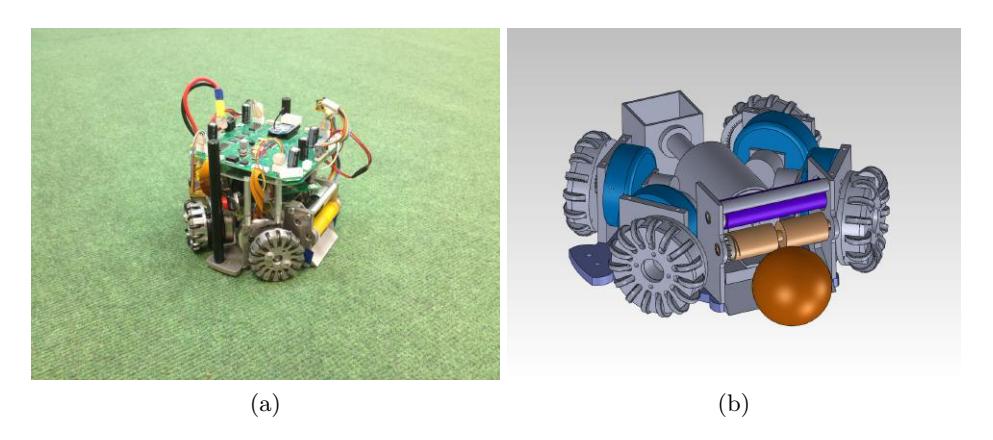
In this section, we will present the mechanical subsystems of the robots. The mechanical design of our robots is similar to other Robocup designs [1–3] in that it is equipped with four custom-built omnidirectional wheels, a dribbler and a kicking system in front.
As listed in Table 1, our new robots meet the mechanical criterion of the Robocup SSL.
After specifying the problems in the wheels, kicker and dribbling mechanism in the old design, the mechanical system is redesigned this year.
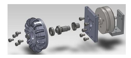
The mechanical subsystem is composed of 3 main components (see Figs. 1– 2): locomotion system, dribbler and kicker. As shown in Fig. 1, the locomotion system consists of a base and four omni–wheels driven by 30 watt brushless DC motors with a gear ratio of 3.6:1. We modified omni-wheels to improve movement abilities and robustness. The wheel consists of 15 O-rings around the base wheel which is redesigned so rollers can turn freely. Also, bigger rollers can be adopted. Material of the wheel is aluminum 7000 series. Both the wheels and the base of the robot were manufactured precisely via CNC tools based on CAD designs.
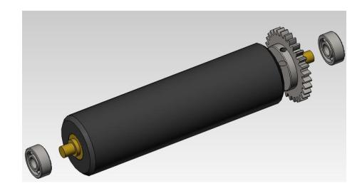
In the new dribbler mechanism, we use Maxon EC16 brushless motor with an embedded gearbox that has a gear ratio of 5.4:1. The gears between the shafts of the dribbler bar and motor are chosen to have a ratio of 1:1. The rotation speed is controlled via an actuator circuit whose input comes from the micro–controller, and it is activated once the robot has the possession of the ball. Different from last year, the dribbler bar is designed as a soft silicon rubber bar. The dribbler is designed to have a ball coverage of less than 20%. The dribbler roller axel has been redesigned (3) to have better rotation. In the previous part, there was an abrasion between the roller and the dribbler arm which used to result in friction and termination in rotation. Also, Material of the dribbling roller has been changed to silicon.
In addition, there is an improvement in the wheel's mounting system and rotating mechanism in order to making it to be dismantled and reassembled easier. Also, it reduces the vibrations during robot's movement. For this purpose, a new encoder and wheel mount has been developed, which brings more precise perpendicularity between the motor shaft and the wheel without any need for extra adjustments. This enhancement provides more reliable directional and rotational motion for the robot.
Also, the axel of wheels has been redesigned. It is armed with two bearings, a bolt and washer in order to have more efficient mechanism with less vibration. Moreover, this feature makes dismantling of wheels becomes easier.
The kicker mechanism contains two 2200 µF, 200V capacitors and two push type solenoid actuated by a kicker circuit. The associated kicker circuit is also controlled by the micro–controller which sends the kick signal and its duration. The robot has two different type of kicking system for direct and chip kicking.
We changed our chip kick actuator to a new one which has longer arms and is wider. Also, one fourth length of its plunger is made of rigid compacted plastic. So, it applies more force and speed to the ball. Moreover, The chip kick system contains a flat shape solenoid. With these specifications, it can kick the ball up to 6 meters.
The direct kicker contains a solenoid and a plunger which lead to kick the ball with maximum speed of 6.5 m/s.
BROCKS Team Robots: Mechanical Specifications.
| Height of the robot | 142 mm |
| Maximum diameter of its projection onto the ground | 175 mm |
| Percentage of ball coverage | < 19% |
Electrical systems
Each of our robots relies on the following electronic circuits that receive commands from the software system in order to perform the desired tasks:
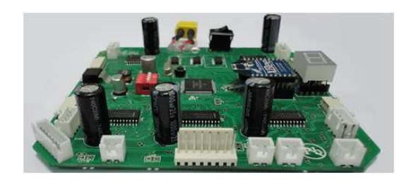
Locomotion Motor Control Circuit: Our robots consist of four custom–built omniwheels, each of which is driven by a 30 watt, 4370 rpm brushless DC motor. The microcontroller is used to estimate the motor speeds and a controller logic is implemented on the microprocessor for precise speed control. Also, the current sensing circuit is implemented to protect the system against unexpected errors by limiting the current flowing through the circuit. Fig. 4 shows the main board of the electrical system.
Dribbler circuit: The dribbler consists of a 15 watt DC brushless motor and it is driven by a simple H–bridge circuit that is controlled by the microprocessor.
Kicker circuit: The design principle of our current kicker circuit is similar to other Robocup designs [2] in the sense that it relies on charging a capacitor to 200 V and then releasing the solenoid once the controlling computer sends the "kick" command [1].
Main Board: For proper implementation of the control strategies on the robots, it is critical that data be communicated to the robots in a wireless fashion that do not violate the rules of Robocup SSL. To this end, we use Zigbee low power wireless communication modules. The control data generated by the main computer are sent to the robots using the wireless modules, which are then received and processed by the microprocessor to carry out the following tasks:
- (a) Measure and control the speeds of four brushless DC motors,
- (b) Activate the solenoid when required,
- (c) Activate and control the dribbler when required.
The electrical subsystems also includes encoders, a gyroscope, an accelerometer and IR sensors as additional sensors in order to get the speed data more precisely. Sequential digital circuit is used to detect the rotational direction of wheels.
Low Level Control
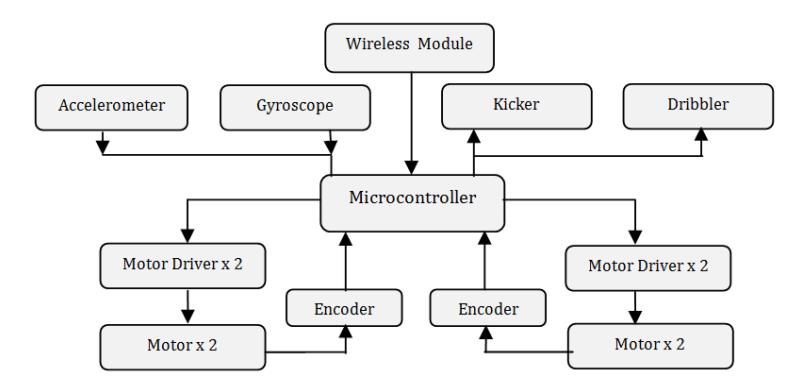
The schematic of our low level control architecture onboard each robot is shown in Fig. 5. The primary task of the low level control unit is to control the motor speeds. The desired motor speeds are sent to the robot via wireless Zigbee transreceiver module from the remote PC. Microprocessor gets the motor speed data from the Zigbee trans-receiver module onboard and activate the speed control loop.
Brushless DC Motors
Maxon EC-45 Flat 30 watt Brushless DC Motors are used for the locomotion of our robots. The motors operate with 12V, at a maximum speed of 4400 rpm and can produce 59 mNm continuous nominal torque. 1:3.6 gear reduction ratio is used in order to increase the overall torque and three Hall sensors with 120 degrees phase difference are available from the motors for speed measurement. The Hall sensors in the motor produce a feedback signal that help estimating wheel velocities. Nevertheless, Hall sensors provide 48 pulses per revolution; therefore encoders which have higher resolution (1440 pulses per revolution) are implemented.
Speed Control
The speed regulation for each wheel is achieved using a digital controller that takes the reference and the estimated speeds as inputs, and adjusts the set point into the actuator [1]. The complete block–diagram of the digital controller is shown in Fig 6 with the variables defined in Table 2 [5].
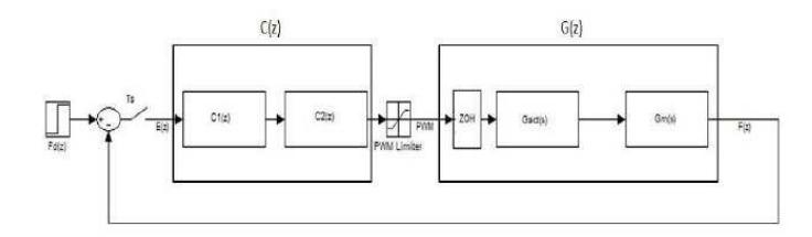
Descriptions of the variables in Fig. 6.
| Fd(z) | z–transform of the desired wheel frequency |
| F(z) | z–transform of the estimated wheel frequency |
| C(z) | Digital PI controller |
| ZOH | Zero–order–Hold |
| Gact(s) | Transfer function of the driver circuit |
| Gm(s) | Transfer function of the motor |
| Ts | Sampling period |
Motion Controller Based on a Kalman Filter Delay Compensator
In this platform, the vision system and its software are responsible for detecting and computing position and velocity of the robot in the field coordinates and send it to the high level control to obtain the error. Apparently, data processing and transmission between these components cause delay in the system response. Also, robot's actuators and sensors produce their own response delays too. That is how, the whole system, as a complex system, faces a considerable delay which can bring many defects to the system. The amount of delay in our system is approximated about 8 camera frames. Note that each frame is about 16.7 millisecond. Now, assume that our robot moves in an arbitrary direction with speed of $2.5 \ m/s$. By a simple calculation, amount of error in term of position measurement is obtained about $33.4 \ cm$. Obviously, this considerable amount of error has destructive influences on the system behavior. Thus, our aim is to compensate this error and its effects. Moreover, after describing the Kalman filter we introduce our path planning algorithm and multi-agent collaboration [1].
Mathematical System Modeling
In this section, we start by introducing a simple model which describes dynamics of the autonomous robot. As far as the high level strategy controller is concerned, the state of the robot can be summarized as the following:
$$s(t) = [x(t), y(t), \theta(t)]^T$$
where x and y represent position of the robot and $\theta$ shows heading of the robot. At this stage, we can claim:
$$s(t+1) = s(t) + T_s u(t)$$
where $T_s$ is the sampling time. Also, u(t) is control signal and equals to:
$$u(t) = [v_x(t), v_y(t), \omega(t)]^T$$
that $v_x$ and $v_y$ are speed of the robot in direction of x and y respectively and $\omega$ is rotational speed of the robot. The objective is that adjust the control signal such that the robot can follow the desired trajectory to the reference point which is:
$$s_r = [x_r, y_r, \theta_r]^T$$
In order to gain such an objective, we need to compute desired speed of each wheel so that robot can achieve the desired coordinate. We use the following equation to compute the desired velocity:
$$\omega_n = -v_{r_n}\cos(\alpha_n) + v_{r_n}\sin(\alpha_n) + (x_{r_n}\sin(\alpha_n) - y_{r_n}\cos(\alpha_n))v_{r_n}$$
where n is number of wheel, $v_{r_x}$, $v_{r_y}$ and $v_{r_\alpha}$ are velocity of robot in robot's origin coordinate in directions of x, y and $\theta$ respectively and $x_{r_n}$ and $y_{r_n}$ are horizontal and vertical distances of the $n^{th}$ wheel from robot's center. Also, A digital PD controller is used for controlling each wheel's motor.
After computing wheels velocities and robot velocity, the velocity of the robot in the field coordinate can be obtained using bellow equation:
$$v = r(\theta)v_r = \begin{bmatrix} \cos(\theta) & \sin(\theta) & 0\ -\sin(\theta) & \cos(\theta) & 0\ 0 & 0 & K_{p_\theta} \end{bmatrix} (s_r - s)/T_s$$
As mentioned before, the system response has considerable delay due to different reasons. So position which the vision system measures and sends to the high level control belongs to D frame before. Hence, the measured output is:
$$s(t) = [x(t-D) \ y(t-D) \ \theta(t-D)]^T$$
In this way, in order to decrease damaging effects of this delay, we implement an augmented system to reduce these effects by predicting future response of the system.
Augmented System Representation
In this part, we will describe the augmented system state equations, which approximates future response of the system. Therefore, to achieve this goal, we define $s_a(t)$, as below:
$$s_a(t) = [s(t), s(t-1), ..., s(t-D)]^T$$
where $s_a(t)$ is state vector of the augmented system. Note that, $s_a(t)$ is a vector with 3(D+1) elements. Defining
$$A = \begin{bmatrix} I & 0 & \cdots & 0 & 0 \ I & 0 & \cdots & 0 & 0 \ 0 & I & \cdots & 0 & 0 \ \vdots & \vdots & \ddots & \vdots & \vdots \ 0 & 0 & \cdots & I & 0 \end{bmatrix}_{m \times m}$$
$$B = [I, 0, \dots, 0]_{m \times l}^{T}$$
$$C = [0, 0, \dots, I]_{l \times m}$$
we construct augmented system's state space representation as:
$$s_a(t+1) = As_a(t) + Bu_a(t)$$
$$z_a(t) = Cs_a(t)$$
where m equals to D+1, l=3, I is identity $3\times 3$ matrix and $z_a$ is output of the estimator.
Kalman Estimator Implementation
After designing the augmented system, we can implement the observer. The Aim of the Kalman estimator is to provide the optimal solution for the above estimation problem. Therefore, considering the (11) and (12), we rewrite them as below by adding white process noise (ξ) and white measurement noise (η).
$$s_a(t+1) = As_a(t) + Bu_a(t) + G\xi$$
$$z_a(t) = Cs_a(t) + H\xi + \eta$$
With known inputs u, white process noise and measurement noise satisfying E(ξ) = E(η) = 0, E(ξξ$^T$) = Q, E(ηη$^T$) = R and E(ξη$^T$) = N, where E(χ) computes expected value of χ, construct a state estimate $\bar{s}$ that minimizes the steady state error covariance which is:
$$P = \lim_{t \to \infty} E({s_a - \bar{s}} {s_a - \bar{s}}^T)$$
The optimal solution is the Kalman with the following equation:
$$\bar{s}(t) = A\bar{s}(t) + Bu(t) + L(z_a(t) - C\bar{s}(t))$$
$$\bar{z} = C\bar{s}$$
The filter gain is calculated using an algebraic Riccati equation, which is:
$$L = (PC^T + \bar{N})\bar{R}^{-1}$$
where
$$\bar{R} = R + HN + N^T H^T + HQH^T$$
$$\bar{N} = G(QH^T + N)$$
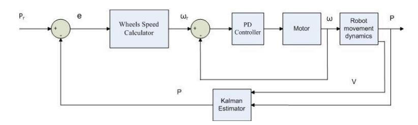
and P solves the corresponding algebraic Riccati equation. Also, $\bar{z}$ estimates the true system output. Fig. 7 shows the control loop of the overall system with Kalman estimator.
Path Planning
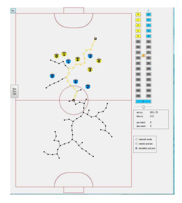
Most path planning algorithms in real–time are based on the standard path planning approach [7]. The path planning system is based on well known RRT family of randomized path planners. The RRT planner searches for a path from an initial state to a goal state by expanding a search tree (Alg. 1). It is also capable of acting in Robocup domain in real–time. The user interface of the path planning algorithm is shown in Fig. 8.
Algorithm 1 RRT Algorithm.
Multi–Agent Collaboration
The key issue in coordinating a team of robots during an SSL game is to decompose the complex task into simpler actions which might be referred to as modes and defining the transitions between these modes in some optimal way [8]. As the constraints and the goals of SSL are known, it is a well-defined environment for developing multi-agent strategies. On the other hand, it is still a challenging test–bed since two teams of robots compete with each other to win the match. The robots should work collaboratively in order to reach success. To this end, we intend to adapt 2 different approaches in developing our multi-formation algorithms:
Hybrid systems based formulation and control: A hybrid system is a dynamical system whose behavior develops as the result of a continuous state system interacting with a discrete event system. We will use hybrid systems in the design of low level and high level control algorithms.
Market driven: The main idea of the market-driven approach is to apply the basic properties of free market economy to a team of robots in order to increase the gains of the team. In adapting the aforementioned technique to our system, we will define suitable metrics in order to select the proper actions at any given time [9].
Concluding Remarks
This paper gives an overview of BRocks 2014, covering the developments of robot hardware and the software architectures. Participation in Robocup 2009 for the first time has helped us improve our team significantly. We are looking forward to compete in Brazil 2014.
Acknowledgements
This work is partially funded by TUBITAK Grant 110E196 and the Turkish Academy of Sciences (TUBA) under the Young Scientists Award Programme (GEBIP).
References
- H. Esen, Hardware and Software Development for Robocup SSL Robots, MS Thesis, Dept. of Electrical Engineering, Boğaziçi University, 2013.
- Robocup Systems Engineering Project, MS Thesis, Dept. of Electrical Engineering, Cornell University, 2002.
- F. Wiesel, Steuerung und Kontrolle von Omnidirektionalen Fussballrobotern, Diplomarbeit der Informatik, Freie Universitat Berlin, January 2006.
- H. Karaoguz, M. Usta, and M. Akar, "Design and Implementation of a Hierarchical Hybrid Controller for Holonomic Robot Formations" Proc. of the 10th International Conference on Control, Automation, Robotics and Vision (ICARCV 2008), Hanoi, Vietnam December 2008.
- H. Karaoguz, "Vision based control algorithms for a small size robot soccer team", MS Thesis, Bogazici University, February 2009.
- M. A. Ruiz and J. R. Uresti, "Team Agent Behavior Architecture in Robot Soccer". In Proceedings of the 2008 IEEE Latin American Robotic Symposium, Washington DC, USA, 20-25, 2008.
- O. Khatib, "Real–time Obstacle Avoidance for Manipulators and Mobile Robots", The International Journal of Robotics Research, 5(90-98), 1986
- H. Kose, K. Kaplan, C. Mericli, U. Tatlidede and H. L. Akin, "Market-Driven Multi-Agent Collaboration in Robot Soccer Domain", in Cutting Edge Robotics, (eds: Kordic, V.; Lazinica, A. and Merdan, M.), Germany, July 2005.
- C. Mericli and H. L. Akin, "A Layered Metric Definition and Validation Framework for Multirobot Systems," RoboCup International Symposium 2008, Suzhou, China, July 15-18, 2008.