EMEnents 2014 Team Description
Usman Shahid, Meysam Tamaar Malik, Umer Javaid, Moeed Saleem, Musaub Shaikh, Awais Amin, Maaz Bin Shahbaz, Muhammad Salman, Bushra Riaz, Kunwar Faraz, Arsalan Akhter, Shoab Khan
NUST College of Electrical and Mechanical Engineering, National University of Sciences and Technology, Rawalpindi, Pakistan
Abstract This paper presents an overview of the technical details of team EMEnents, the Robocup Small Size League Team from NUST College of EME, Pakistan for the year 2014. The paper discusses the current status of the team and the progress of the system developed so far.
1 Introduction
Team EMEnents is an interdisciplinary team at NUST College of Electrical and Mechanical Engineering, a constituent college of National University of Sciences and Technology, Pakistan. The focus of the team for the current year was to restructure the software implementation as well as to generate low budget electronic hardware. Software implementation of the game play and planning modules has been redesigned this year in a new programming environment. C# was selected for implementation of the system due to its extensive support and pre-compiled directives as well as better GUI support. The main electronic board of the system was built around PIC microcontroller due to more interrupt handlers in PIC as compared to BeagleBone of last year. The task of design & fabrication of the mechanical structure of robot was completed last year. This year we are using the same mechanical structure.
The paper is organized as follows. Section 2 of the paper discusses the current electronic design of the robot. Section 3 discusses the mechanical design, section 4 discusses the software architecture, section 5 discusses vision data acquisition using SSL vision, and section 6 concludes the paper.
2 Electronic Design
The Electronic Design Circuitry can be broadly classified into the following parts.
2.1 Processing Unit
This year we are using Microchip's PIC18F47J13[1] as a central processing unit. Last year we used BeagleBone, and its processing power was utilized on-board for various computations. The reason behind using PIC microcontroller instead of BeagleBone is the huge difference in their costs as well as more number of interrupt handlers. Due to its lower processing power, some additional processing and computation will be done on the AI server. The features of PIC18F47J13 that we are utilizing are:
- UART for interfacing with XBee modules.
- Independent PWM channels: 4 for wheels, 1 for dribbler, 1 for boost circuit.
- Input capture modules for sensing motors encoders feedback
- Sensing feedback from IR sensor
- Support for implementation of Kicker and Chipper Module
- Support for implementation of Dribbler Module
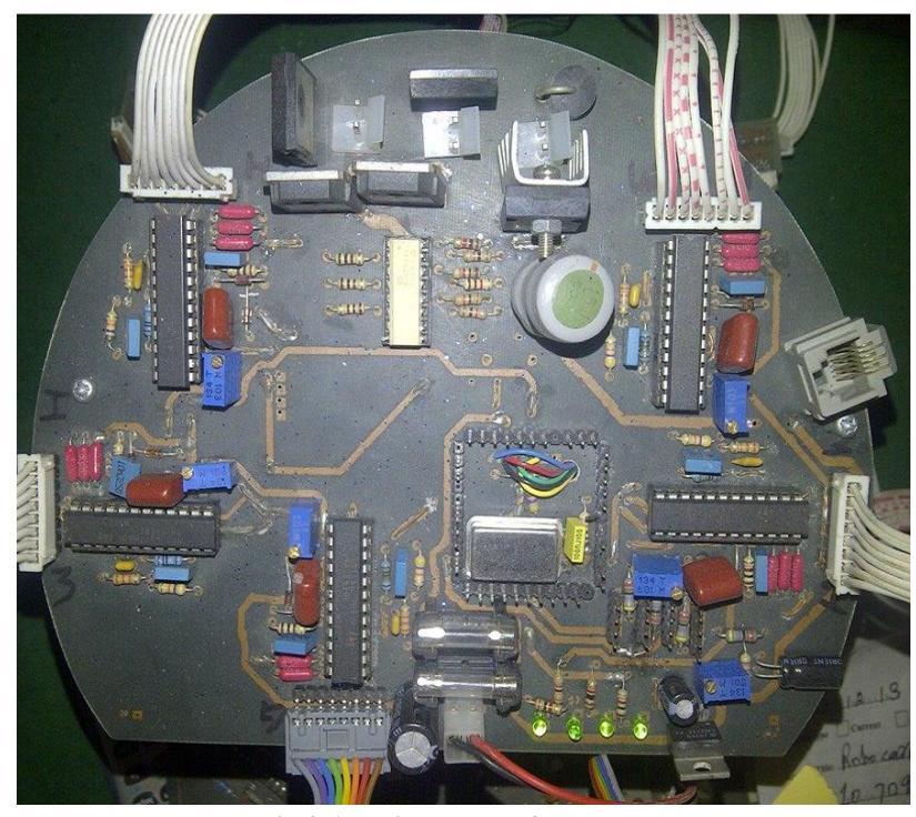
Fig 2.1 shows the main board of the robot. The difference between current year's board and last year's main board is the implementation of all modules on one, multi layered PCB. The facility for on-circuit debugging of the microcontroller has also been added on the board. All of the algorithms of the robot's modules like motor control, wireless communication, kicker and dribbler modules have been successfully implemented on this board.
2.2 Motor Control Circuitry
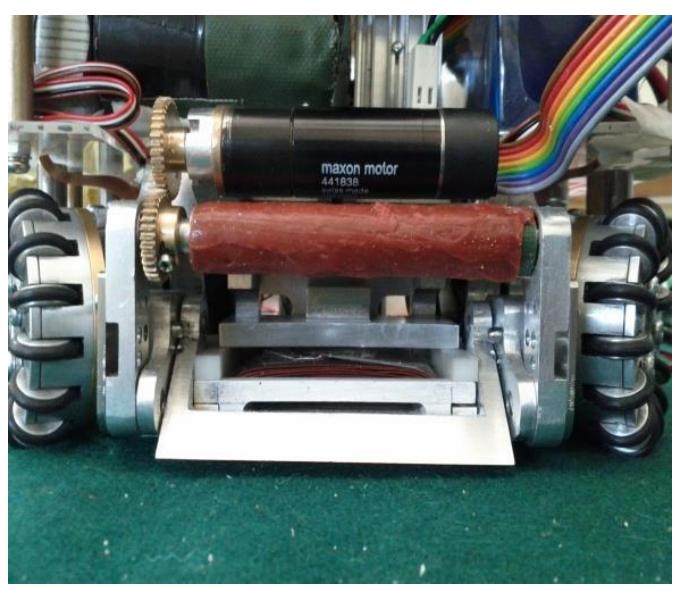
As in last year [2], Maxon EC 45 Brushless DC motors were selected as wheel motor and Maxon EC 16 as dribbler motor, whereas L6235 is used to drive these motors. The L6235 IC includes all the circuitry needed to drive a three-phase BLDC motor including a three-phase DMOS Bridge, a constant off time PWM Current Controller
and the decoding logic for single ended hall sensors that generates the required sequence for the power stage.
Feedback control is also implemented using US Digital E4P optical encoders attached separately with each wheel motor with a custom made back-extended shaft. Each module takes 3 inputs for each motor; PWM, Direction and Brake. Each robot contains a total of five L6235 modules, four for the wheel motors and one for the dribbler motor.
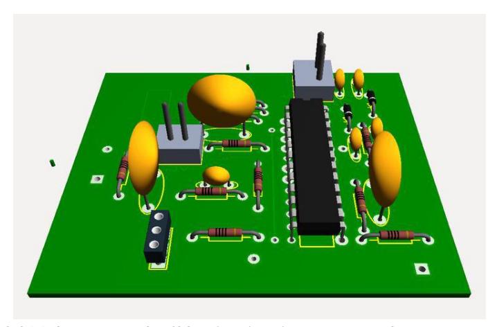
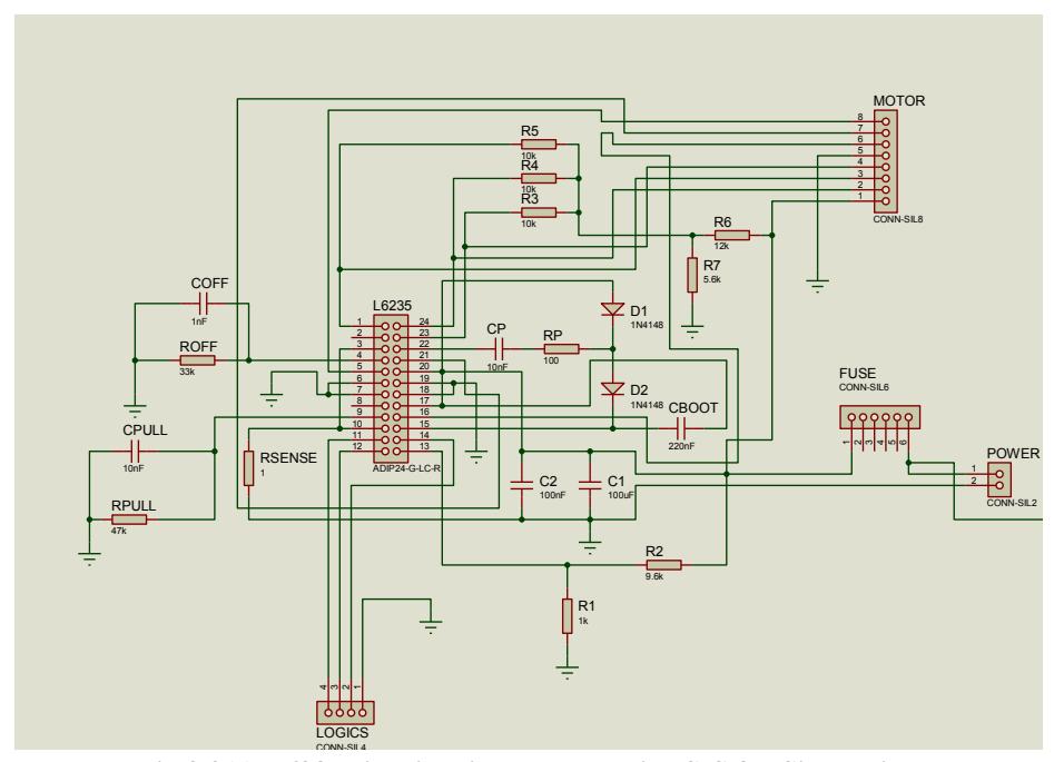
Pulses generated by the encoders are fed to PIC which helps in determining the speed of the motor. As per set point, PID loop is implemented by PIC by providing required output PWM to L6235. Data received wirelessly will determine the speed and direction of each motor as required by movement of robot. Fig 2.2(b) shows the 3D model of L6235 based circuitry implemented for motor control. ISIS design is shown in Fig 2.2(c)
2.3 Wireless Communication
For wireless communication between the robots and the AI server, Zigbee (802.15.4) based XBee Series 2 modules have been used due to their efficiency and ease of use. These modules are 3.3V logic devices. Since PIC18F47J13 is also a 3.3V device so interfacing both the modules becomes very easy. The modules are configured in API mode in a point-to-multipoint topology in order to transmit and receive an entire frame of data. This frame consists of fields containing the information regarding motion control, kicking system, dribbling system. The format of the data packet is shown in Fig 2.3
Fig.2.3 Packet format for communication from AI Server to the Robot
| Field | V1 (velocity in mm / sec of wheel 1) | V2 (velocity in mm / sec of wheel 2) | V3 (velocity in mm / sec of wheel3) | V4 (velocity in mm / sec of wheel 4) | Kick Speed | Chip Kick | Dribble | Flat Kick |
|---|---|---|---|---|---|---|---|---|
| No. of bits/bytes | 2 Bytes | 2 Bytes | 2 Bytes | 2 Bytes | 3 bits | 1bit | 1bit | 1bit |
Currently we are employing one way transmission from the AI server to the robot, but we also plan to send the status of robot battery and control parameters from robot to AI server for features such as online debugging in future.
2.4 Ball Shooting Mechanism
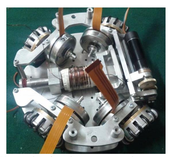
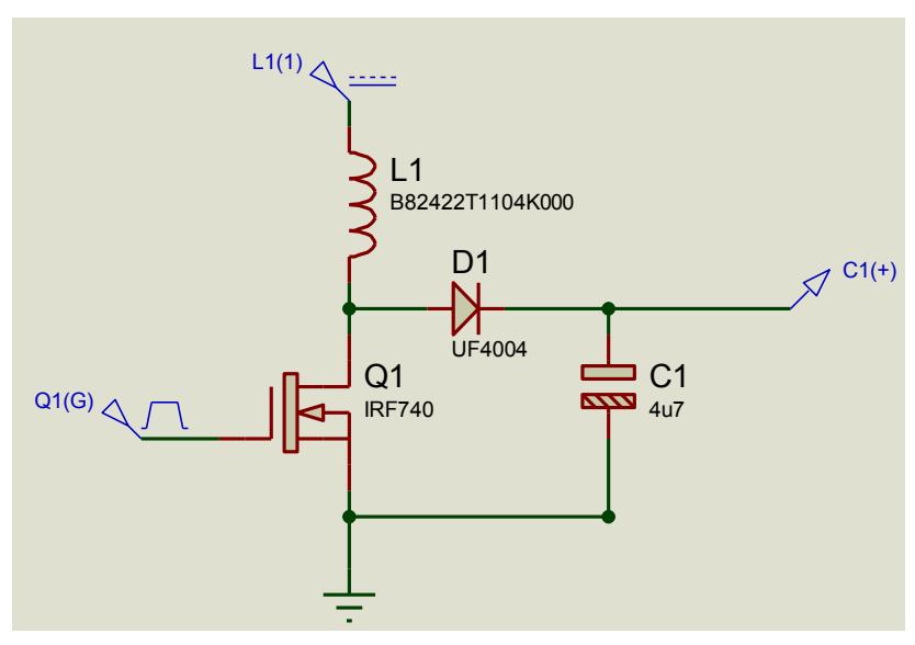
For our kicking system, we are using solenoid based kicking carried out using a custom built solenoid. Two 2200 uF capacitors are charged to 200V by a boost circuit. Our robots have two kicking mechanisms, namely flat kick and the chip kick. The solenoid used for flat kicking has 700 turns of AWG 25 wire, while the chip kicker has 350 turns of AWG 25 wire. The kicker system is capable of delivering ball speeds as high as 10m/s, which is then limited to 8m/s in software as per the F180 rules.
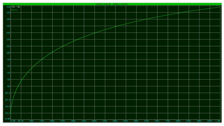
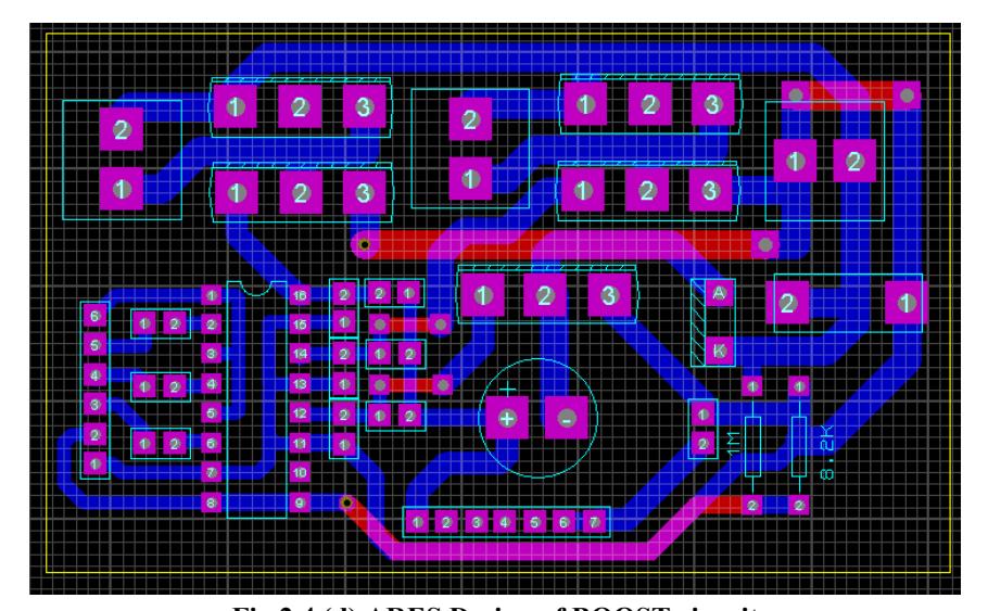
An IGBT based circuit drives the kicking mechanism, where the kicking speeds are controlled by changing the on-time of IGBTs. The Boost converter circuit was designed (Fig 2.4(b)) and simulated (Fig 2.4(c)) in ISIS and after final tuning its PCB design was made in ARES (Fig 2.4(d))
3 Mechanical Designs
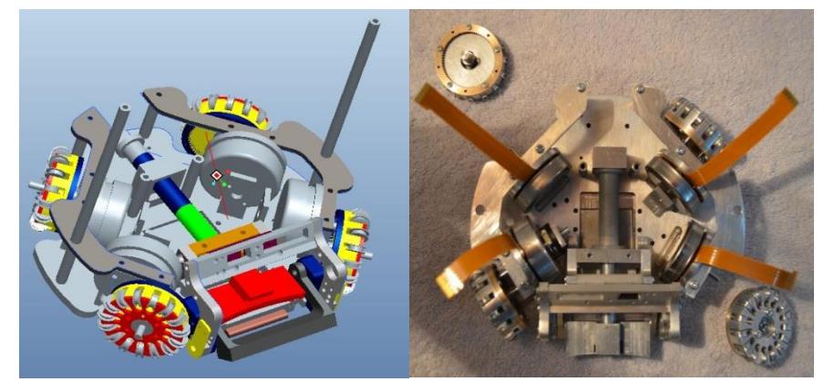
Mechanical Designs of the robots used in Robocup Small Size league share the same basic structure. The designs of our robots were inspired from Skuba [3], which have a modular design, making the robot easy to debug in case of any problem. Fig 3.1 shows the complete CAD assembly of the robot, which was generated using the design software Pro-Engineer Wildfire. Dimensional limitations as per Robocup SSL were followed strictly to keep robot within 180 mm diameter and 150 mm height. All parts were fabricated indigenously under supervision of our hardware team.
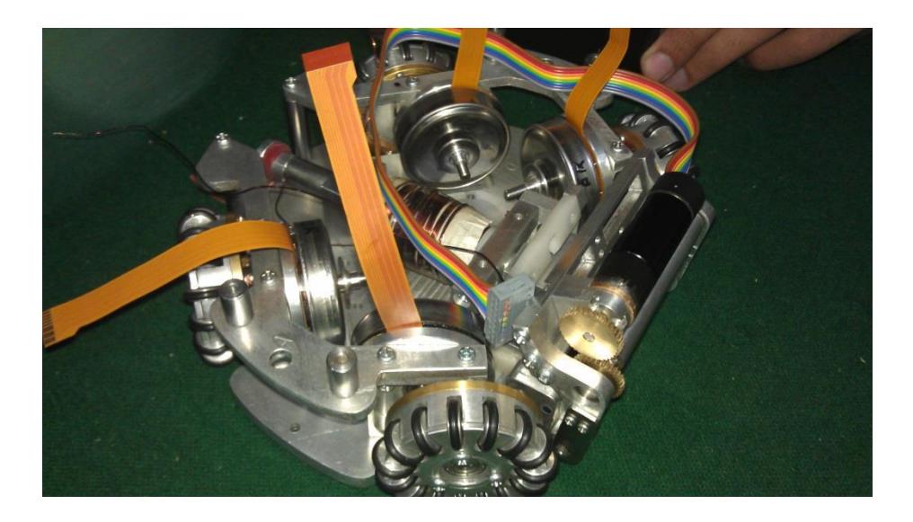
Fig 3.2 shows final fabricated assembly of the robot. Further improvement in the design includes selection of appropriate materials for gears, using appropriate wheel diameter and better motors etc.
4 Software Architecture
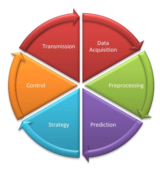
The high level software architecture follows a modular approach. Different modules work collaboratively by following the model of a Kahn Process Network [4] i.e. a module works after receiving input from previous module through a blocking read. In short the output from one module is being used as input to the next.
Also, this year we have shifted to C# from last year's C++ implementation. C# has better tools available for GUI development as well as better high level features as well as quick development time.
4.1 Prediction
The module is present to compensate for the delay due to the real-time nature of the system. The module predicts the short term future values from the received position of the ball and robots through spline numerical interpolation in order to minimize the effect of noise and further facilitation in decision making.
4.2 Strategy
The current approach divides the field into 24 unequal portions, where each portion has a role attached to it. Any robot which is in a certain portion is dynamically assigned that role. Smaller portions near the goal are assigned to the goal-keeper and defenders and mid-fields etc (goal-keeper is fixed). These roles are assigned lower level/primitive tasks such as kick, dribble etc. Combinations of these profiles are maintained to help in upper level decisions such as whether Strategy1 (which may be one combination of a set of maneuvers) should be employed or Strategy6, etc. The dynamic role allocation is done again after a certain profile is executed.
4.3 Control Module
The product of the strategy module is a set of final positions and actions to be performed by each robot. The purpose of the control module is to plan a path between the current position and the final position of each robot while avoiding obstacles. MT-D* Lite [5] is used for path planning, where the field has been divided with a resolution of 10mm. Once this is done, the control module provides linear and angular velocities along with other command for each robot on the field. The commands are then transmitted to the robots through the above discussed Xbee modules.
5 SSL Vision
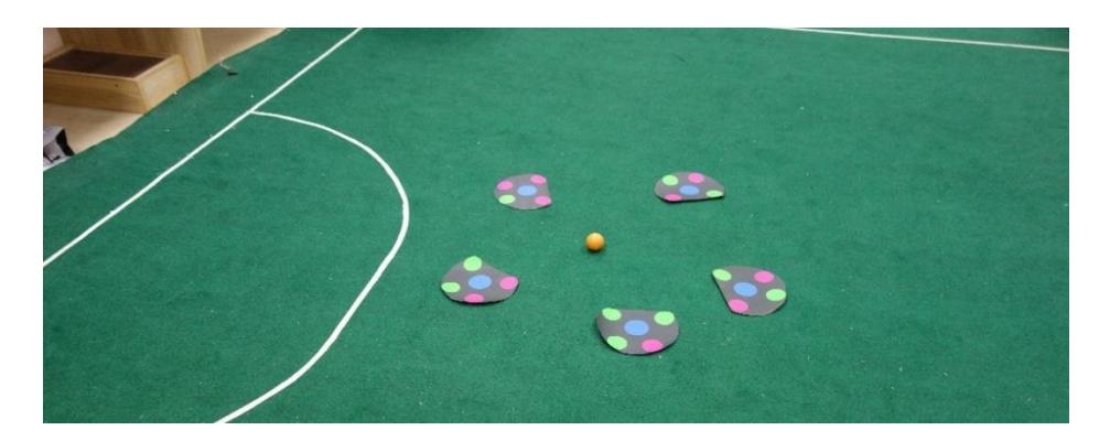
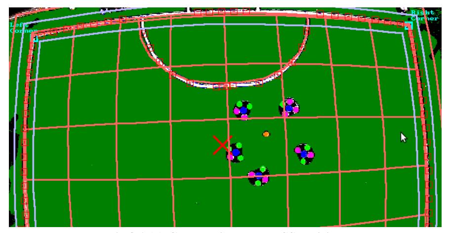
For acquisition of vision data, SSL vision was employed. The Actual field and results of the calibration are shown in the figure 8.1(a) and 8.1(b) respectively.
6 Conclusion
The Team Description paper outlines the general architecture of our software and hardware system and lays a foundation of the system as a whole. The paper also sheds light on the future projections and directions towards which the team intend to move. We, as a new team, look forward to having a contributing and learning experience with other teams and the SSL community in the future.
Acknowledgements
We are thankful to National University of Sciences and Technology, Pakistan and Higher Education Commission of Pakistan for the initial funding for the said project.
References
- PIC18F47J13 Family Data Sheet Microchip Corp.
- Arsalan Akhter , Usama Tariq Butt , Mahmood Azhar, Syed Mohsin Raza, Taimur Ahmad, Ghina Zia, M. Shahzad Bhatti, Jahanzaib Sohail, Muneeb Arshad, Zain Imran, Asif Mehmood, Mesum Tamaar Malik, Taousif Iqbal, Abbas Amir, Muhamamad Salman, Kunwar Faraz, Shoab Khan, "EMEnents 2013 Team Description" In the Proceedings of Robocup 2013.
- Krit Chaiso, Teeratath Ariyachartphadungkit, Kanjanapan Sukvichai: Skuba Team Description. In the Proceedings of Robocup 2011.
- E. A. Lee and T. M. Parks, "Dataflow Process Networks," Proceedings of the IEEE, May 1995.
- Xiaoxun Sun, William Yeoh, Sven Koenig, "Moving Target D* Lite". Proc. of 9th Int. Conf. on Autonomous Agents and Multiagent Systems (AAMAS 2010)