FURGbot 2014 Team Description Paper
Sidnei Carlos da Silva Filho, Eduardo do Amaral, Gerson Urban, Matheus Machado, Joel de Oliveira, M´arcio Gon¸calves, Floricio Teixeira, Alexandre Horn, Luan Silveira, Pedro Ballester, Vagner Rosa, Emanuel Estrada, Paulo Drews, Silvia Botelho
Universidade Federal do Rio Grande, Rio Grande, RS, Brasil
Abstract This paper describes an overview of the FURGbot team, a Small-Size league robot soccer team. The system is designed to participate in Robocup 2014. The hardware, software and mechanical components are described in this paper.
Introduction
The FURGbot Small-Size Team is a project of the Center of Computational Science from Federal University of Rio Grande, Brazil. Our objective is to stimulate robotic research and education in applications in the field of robotics, artificial intelligence, embedded systems and control theory. The FURGbot Team was created in 2006 by undergraduate students. We have won the Brazilian Championship six times and the Latin American Competition one time.
A more robust embedded system and a new off board software will be available for RoboCup 2014. This paper details our approach for this competition. Section two describes our mechanical structure. Section three exposes the new hardware modules. Finally, the new off-board system, based on the STP Architecture [1], is described on section four.
Mechanical Structure
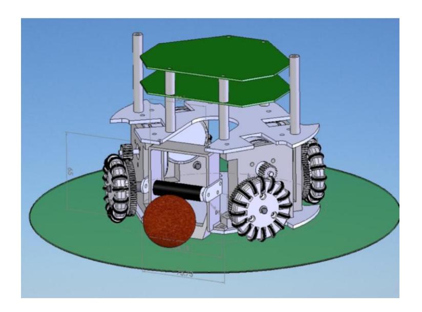
The mechanical structure of the robot is made of an aluminium base and four omnidirectional wheels, see Figure 1. Each wheel is drives by an motor, with the coupling made by a gear to reduce the angular velocity. The base still has a dribbler device, made by a rubber cylinder coupled to the motor and kick devices, which uses a solenoid.
Embedded Eletronics
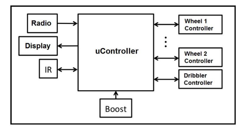
The robot must be able to run, kick, pass and dribble, and moreover it needs to be compact and robust. Furthermore, due to the highly dynamic environment of the game, the robot needs to be fast, accurate and have low power consumption. Figure 2 shows an overview of our architecture, detailed in the next subsections.
Processing Unit
The robot presents a dribbling device and a high/low kick, allowing the performance of more elaborate moves. Furthermore, there is a motor speed control system that uses Hall-effect sensors, battery load control sensor, ball detection sensor and others. We use a Arduino Mega 2560 micro-controller to address the needs associated with the number of I/O pins, channels of PWM (Pulse Width Modulation), serial ports and analogue to digital converters.
Motors and Drivers
The motors used to drive the wheels are the model EC-45 - 30W from Maxon company. Unlike brushed DC motors, these motors have no physical contact and internal motor abrasion. However their drivers are more complex [2]. This engine model has internal Hall-effect sensors that makes possible to do a wheel speed control even with a low-resolution encoder.
To drive the dribbler we used another type of motor, the EC-16 - 15W. This model is smaller and faster than the other, but it has the same electrical features of the wheel motors.
Passing and Kicking
The difference between a pass and a kick is obtained by controlling the discharge of a capacitor bank. These capacitors of 470uF each are grouped by six. To charge the capacitors a DC-DC converter circuit is used [3], built on a separate board and isolated from other components in order to avoid noise that might cause damage.
Furthermore, to control charging of the capacitors, not allowing the charge voltage to exceed the maximum of 250V or reach a lower limit of 200V, voltage comparators were used. The circuit also allows, in accordance with the signal from the micro-controller, the way of the kick (high or low) and speed are selected, allowing more elaborate moves and passes.
Ball Detection
Infrared sensors are responsible for detecting the ball and allowing the kick. A signal is sent to the controller indicating the presence or absence of the ball. In previous versions, due to interference from ambient light, the sensors did not work correctly. The solution to the problem was the use of an integrated circuit capable of comparing the signal emitted by the infrared LED and received by the photo-transistor. Image 3 shows the operation of the designed circuit.

Software
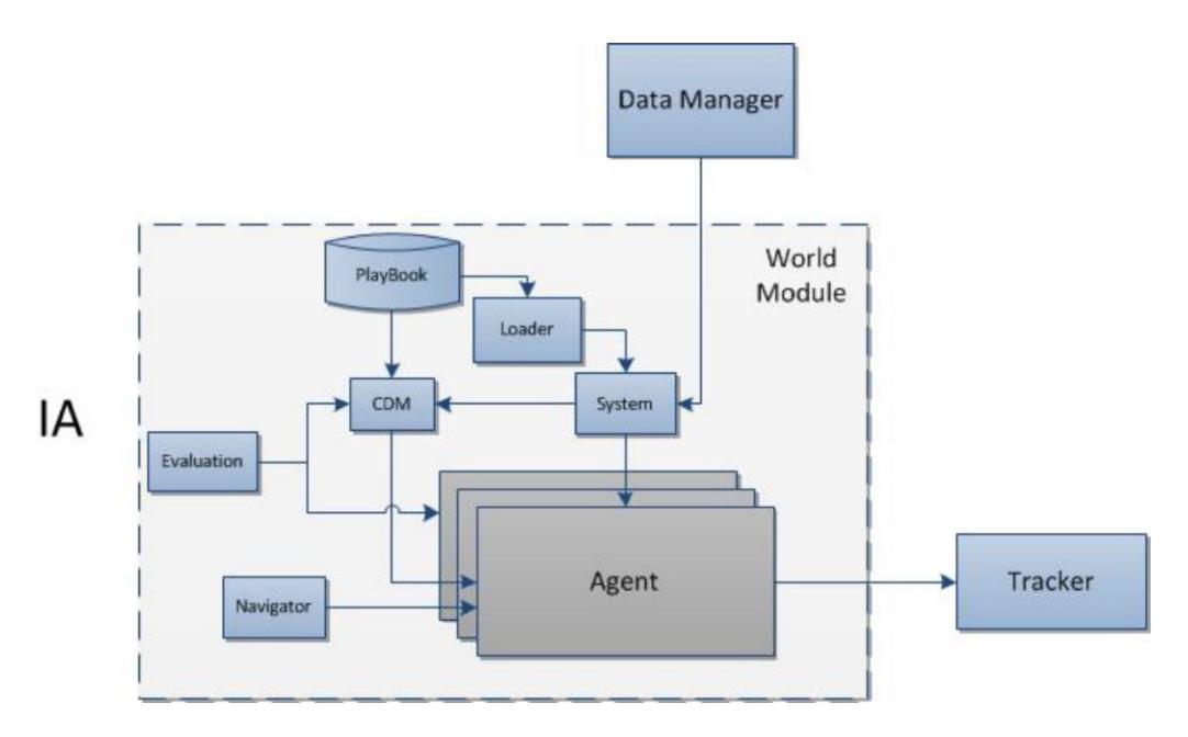
With an significant increase of the embedded system performance, it was possible to invest in a more complex and robust off-board software architecture. This system is divided in three main modules: the Tracker, the Data Manager and the AI Server. The components of the system are shown on figure 4.
Conclusion
This paper presents an overview of the FURGbot 2014 project. The team consists of undergraduate students at the FURG. This year we have a more robust embedded electronic and a new off-board software. An overview of our architecture, mechanical structure and software control and strategy was presented.
As future work we intend to test and validate all modules, aiming to deal with uncertainties, noise and unanticipated failures.
References
- Browing, B., Bruce, J.B.M., Veloso, M.N.: Stp: Skills, tactics and plays for multirobot control in adversarial environments. (2005)
- Kenjo, T., Nagamori, S.: Permanent- magnet and brushless dc motors. (1985)
- Mohan, N., U.T.M., Robbins, W.P.: Power electronics: Converters, applications, and design. (2002)
- Meinhold, R.J., Singpurwalla, N.D.: Understanding the kalman lter, the american statistician. (1983)
- Bruce, J., V.M.: Real-time randomized path planning for robot navigation. (2002)
- Atramentov, A., L.S.: Efficient nearest neighbor searching for motion planning. (2002)
- CGAL: Computational geometry algorithms li brary (n.d.). http://www.cgal.org. (2013)