2014 KIKS Extended Team Description
Soya Okuda, Kosuke Matsuoka, Tetsuya Sano, Hiroaki Okubo, Yu Yamauchi, Hayato Yokota, Masato Watanabe, Toko Sugiura
Toyota National College of Technology, Department of Electrical and Electronic engineering, 2-1 Eisei-cho, Toyota Aichi, 471-8525, Japan
http://www.ee.toyota-ct.ac.jp/~sugi/RoboCup.html
Abstract This paper presents a detailed description of KIKS in addition to the team description paper of small size league in RoboCup 2014. Our robots and systems are designed under the SSL 2014 rules in order to participate in the RoboCup competition. The major improvements in this year are the enhancement of the performance of wheels, electrical circuit and automatic control system. The overviews of them are described. Keywords: RoboCup, small-size league, engineering education, global vision
Introduction
In last year, we improved the robots to obtain better performance. But there were some problems for passing performance and electronic circuits of the robots. So we checked them this year, and redesigned for some term mentioned above. In addition we also improved motion control method to obtain better acceleration performance with a little skid. The main topics of development for robot in 2014 model are following terms,
- ・Improvement of the kicking device
- ・Improvement of the electric circuit
- ・Improvement of the motion controller on the AI system
Hardware of the robot
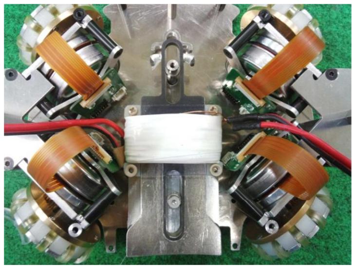
In our opinion, passing performance will be more important for the large-size field. So, we tried to increase passing precision of the ball when the robot kicks it. The improved bar of solenoid is shown in Fig. 1. In previous robot, there was only one guide pin in vicinity of center of the robot. It was because it avoids excessive friction. But, it was found that the solenoid bar was fluctuated left and right when the straight kick is done. Thus, we added second pin as a guide in enough space between coil and straight kick bar. That is, the solenoid for straight kick has two guide pins at back and forth of coil. In addition, a bearing is used in the contact point for each pin and bar to prevent abrasion of the materials.
Electrical design
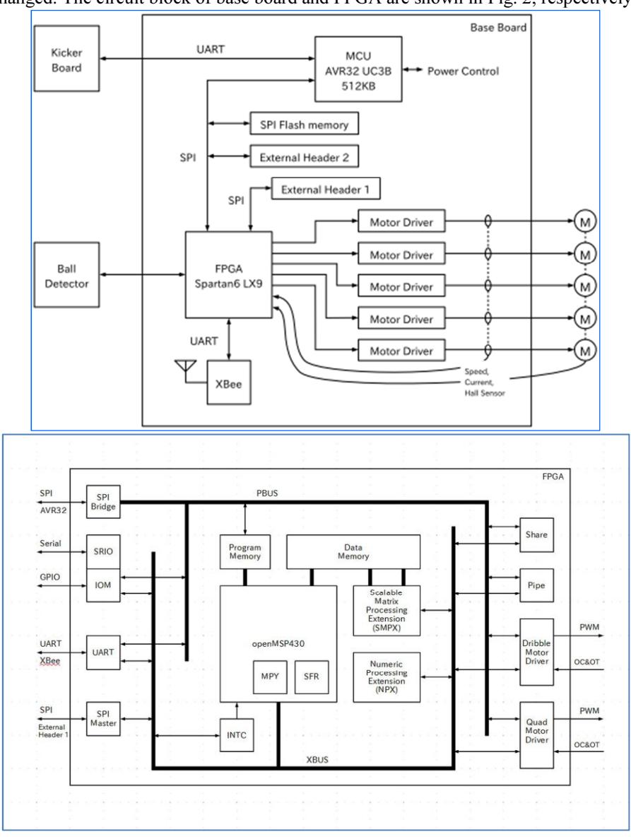
The electronic circuit is mostly same with last year, but the system in FPGA was changed. The circuit block of base board and FPGA are shown in Fig. 2, respectively.
Specification of MCU
The built-in memory of MCU is storing the program of two kinds of modes, i.e., APP (Application) and DFU (Device Firmware Update) modes. DFU mode is used for rewriting the SPI flash memory and the built-in memory of MCU. On the other hand, APP mode is used for operating a robot. Because of safety, both of flash memory cannot be rewritten in this mode.
New system in FPGA
We renewed system in FPGA to use floating point number at programming of softprocessor. Thus far, soft-processor could not allocate memories to use floating point number because the system in FPGA which has a complicated internal structure was using many memories. Therefore, we have simplified internal structure. Thus, softprocessor acquired ability to perform a floating point number operation and matrix operation.
Motor Driver of Base Board
Five motor-driver ICs (DRV8832) are mounted on the base board. Four of them are for the travelling wheels and one is for the dribbling device. Each wheel's motor has a magnetic encoder (AS5145). We chose a magnetic encoder because it is cheap and high-performance compared with an optical encoder.
New PC Software for circuit
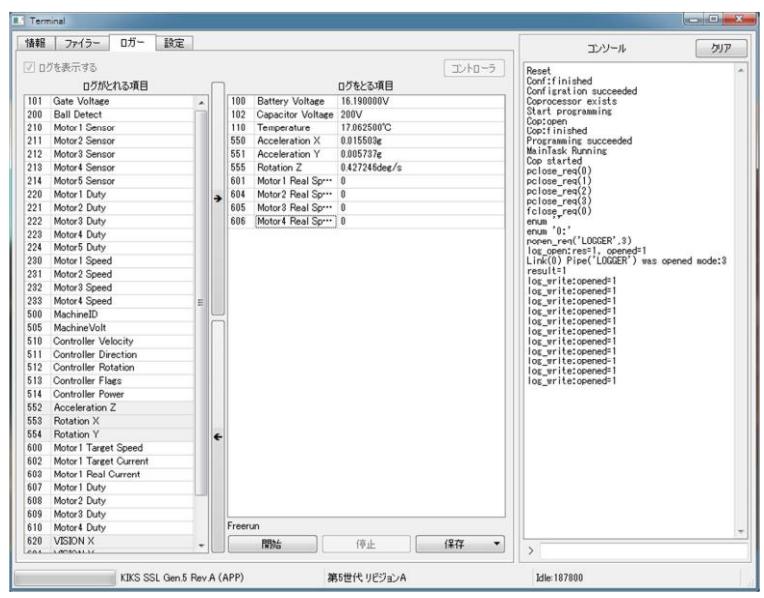
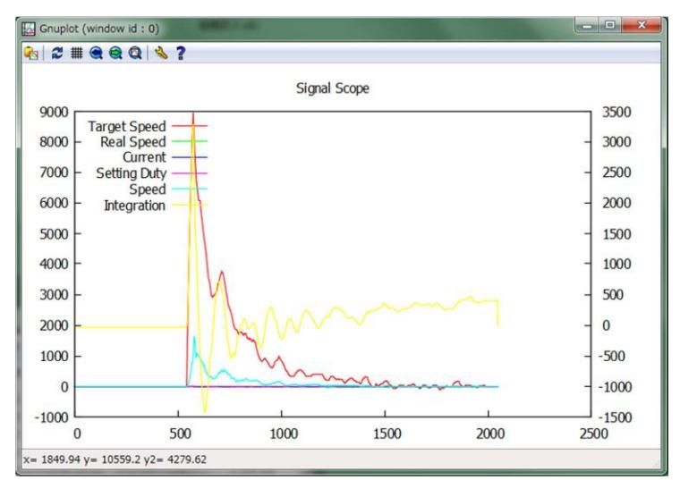
We developed software to obtain the information of our circuit. All data (e.g. data such as battery voltage, capacitor voltage and angular velocity of each motor etc.) of a circuit can be observed in this software. These data can be outputted to the file of CSV or VCD format, (and the file of PLT format for gnuplot can also be generated automatically and evaluated). Furthermore, this software can also rewrite the firmware of the robot in DFU mode.
The execution screen of the software is shown in Fig. 3 and the capture image of gnuplot is shown in Fig. 4. This software can also write into soft-processor in FPGA with HEX format program by means of two methods. One is a mode of completely stored in Flash memory (a robot is in DFU mode then),, and another is that of temporarily stored (a robot is in DFU or APP mode then). The temporary store means that it will be back previous program when the power supply is shut down. By applying this method, it will be convenient for debugging.
Inertial Measurement Unit for base board
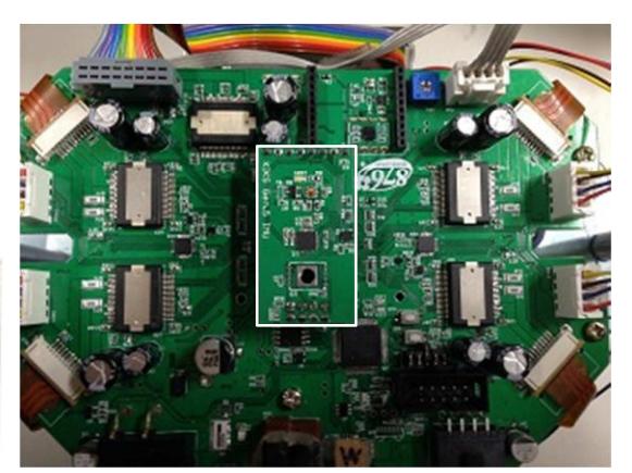
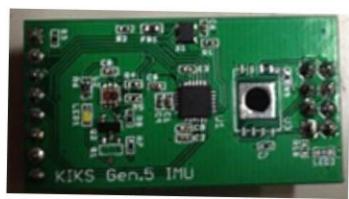
We built a scalable system for circuit. One of them is a terminal connector for addin boards in a circuit. It is necessary for advanced control of robot to mount IMU (Inertial Measurement Unit). The pictures of new designed IMU and the FPGA board are shown in Fig. 5, respectively. Thus, now we can use gyroscope sensor and accelerometer by using this add-in board. We have a plan to try new control system by using the value from IMU with software descried in §3.1.
Evaluation of IMU
We tried to evaluate for motion velocity of robot by using IMU. As the results, it was found that there was an error between robot speed estimated from acceleration of IMU and that of estimated from angular velocity of wheels. This means that the slip of wheel is occurred in robot.
We are considering an introduction of somewhat slip ratio control method which is used in electric vehicle. We would like to test this control method by using the value obtained from IMU and SSL-Vision.
Software design
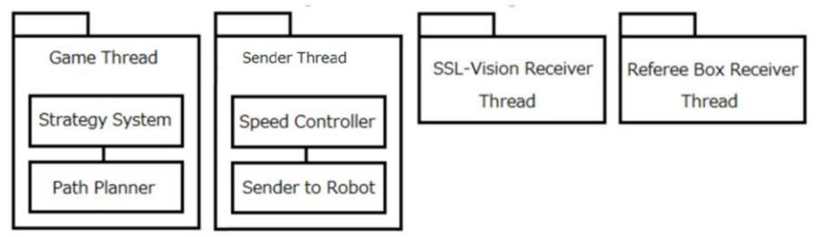
Our AI server is called SIS (Strategy Information System). The SIS consists of four threads as shown in Fig. 6. There are "Game Thread", "Sender Thread", "SSL-Vision Receiver" and "Referee Box Receiver". The analysis of strategy and action for all robots are executed in "Game Thread".
In 2014, we tried to modify the structure of "Strategy System" in "Game Tread", and improve the "Speed Controller" in "Sender Thread".
Improvement of the structure of strategy system
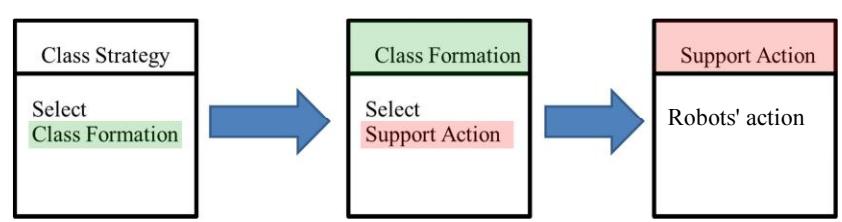
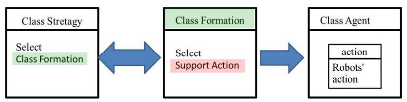
A previous structure of the "Strategy System" shown in Fig. 6 is constructed from three modules. It is shown in Fig. 7. First, it is chosen the "Class Formation" corresponding to the Referee box's signal in "Class Strategy". In next "Class Formation", it is chosen the "Support Action" corresponding to the game situation for each robot. Finally, the "Support Action" makes a decision how do robots work. For example, There are actions such like [kick a ball] and [move a robot] in the "Support Action" library. When the "Class Formation" decide to make kicking a ball for a robot, it chooses [kick a ball] in the "Support Action" against robots.
In previous structure, the "Class Formation" decided all robots' action analyzing from the situation of game. But, we have to construct more flexible "Class Formation" to promote a smart and intelligent gameplay. It is difficult to develop more complex "Class Formation" because it is required many "Support Actions" and branch condition for intelligent behaviors. It is also hard to reuse the previous program. Therefore, we tried to introduce newly-proposed "Class Agent" in new strategy system as shown in Fig. 8 to develop program more efficiently.
The "Class Agent" is a class that selects appropriate Support Action depending on given role in game. In new structure of Fig. 8, the "Class Formation" decides only each robot's role. The knowledge and intelligence to play a given role is kept in the "Class Agent". As the results, we could develop more efficiently programs which have flexible intelligence by introducing of this structure.
About controller of Robot
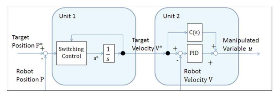
Last year, we developed controller which has two control units as shown in Fig. 9. To realize stable and speedy robot's motion, it is necessary to control within the robot's limitation of acceleration. It is achieved by using sliding mode control that is one of nonlinear control on the basis of explicit limitation of acceleration. We can get the target velocity $V^$ from target position $P^$ and current position P in Unit1 of Fig. 9. The Unit2 is enable us to know current velocity V following $V^$ by using two-degreeof-freedom control. In case of use of this theory, it is required a high followingperformance for robots to make $V = V^$ in Unit 2. However, we could not construct appropriate structure of Unit2 last year. In this year, we tried to identify ideal robot model by using genetic algorithm, and design ideal Unit2 on the basis of the results after that.
Identification of model by using Genetic Algorithm
Velocity of the robot is expressed in transfer function as following equation,
$$V = \frac{ks+t}{s^2+2\zeta\omega_n s+\omega_n^2} u \tag{1}$$
where, $\zeta$, $\omega_n$, k, t are constant coefficients that define characteristics of robot, and udisplays the manipulated variable in Fig. 9. Eq. (1) is equal to transfer function of
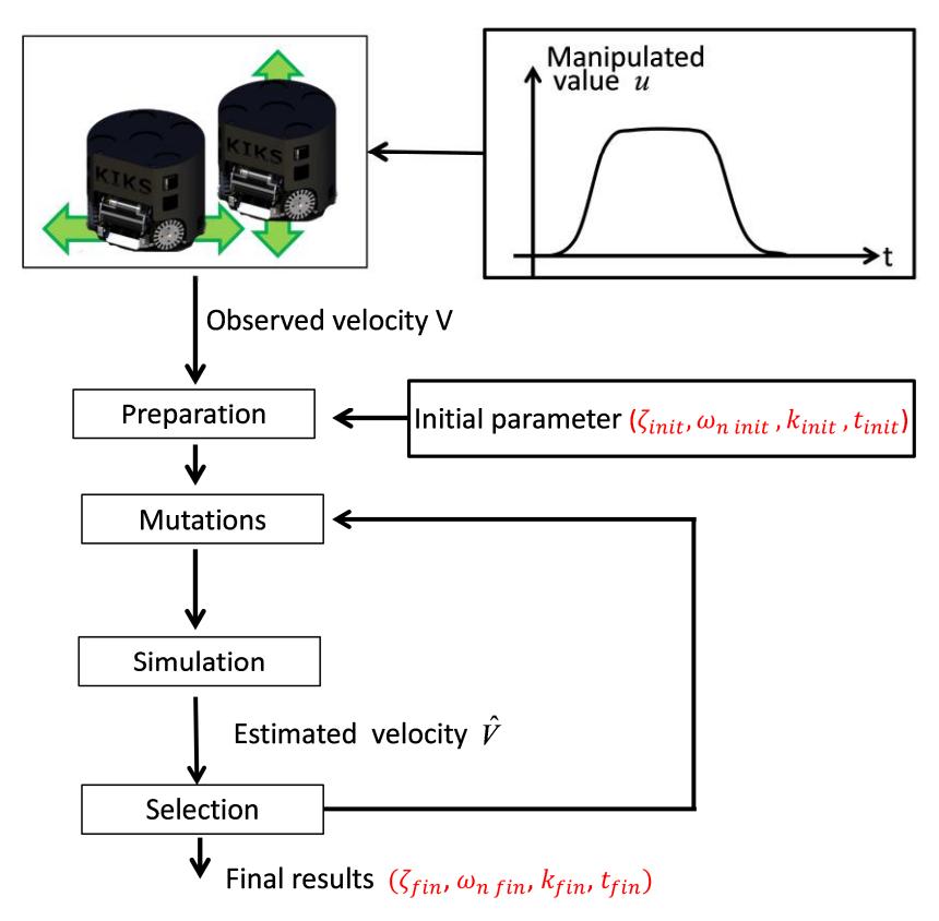
adfa, p. 8, 2014. © Springer-Verlag Berlin Heidelberg 2014 speed control of motor with PI control. In this system identification process, the genetic algorithm (GA) is used to get most probable parameters of $\zeta$, $\omega_n$, k, t. Figure 17 shows a program flow of system identification process with GA.
We evaluated the performance of obtained model by analyzing mean square deviation
$$\Delta V = \sqrt{\frac{1}{T} \int_{0}^{T} \left{ V(t) - \hat{V}(t) \right}^{2} dt}$$
of robot's observed velocity $V$ and estimated velocity $\hat{V}$. Arbitrary target velocity $V^$ is given to a robot. Next we get the velocity V(t) from target velocity $V^(t)$ by going through the unit 1. Then we carry out GA and able to produce a motion models based on the parameter for each robot. But, we cannot directly get the valid value because of the noise contained in the robot's position $P^*$ on vision system. So, by increasing of number of the motion, an influence of white noise for average of $\Delta V$ was decreased.
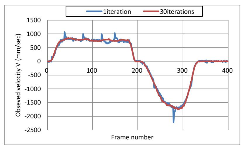
We did experiment to evaluate about mentioned model by using real robot. In the experiment, we used 100 for population of GA and number of generations, respectively. The dependence of iteration count for observed velocity in back-and-forth motion
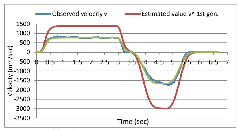
is shown in Fig. 11. It is found that as increasing of the number of iteration of motion, noise on the average velocity is decreased. The estimated velocities for first and final generation are shown in Fig. 12. As increasing generations, it enable us to give smaller $\Delta V$ by applying of GA algorithm.
At first of identification, the robot's velocity V is investigated when the trapezoidal acceleration command value. Next, it is analyzed $\zeta$, $\omega_n$, k, t that robot's estimated velocity $\hat{V}$ follows with trapezoidal velocity V. The results for experiment of 1st and 400th generations on GA are also shown in Fig. 12. It is found that the estimated velocity $\hat{V}$ is good agreement with the observed value V in Fig. 12. All control logics in SIS are made by using results of identification mentioned above.
Optimization of Unit2
We identified the appropriate parameter of control model for Unit2 in §4.2.1. As mentioned above, the Unit2 ensure following performance by using two-degree-of-freedom control. It is necessary to be equal to one for value of whole transfer function of nominal plant in order to making $V^* = V$. Thus, C(s) in Unit2 is designed in following eq. (2) as reverse expression of control system.
$$C(s) = \frac{s^2 + 2\zeta \omega_n s + \omega_n^2}{ks + t}$$ (2)
By using eq. (2), whole transfer function is theoretically equal to 1. In fact, however, the parameters $\zeta$, $\omega_n$, k, t derived in GA are not strictly true. So, the Unit2 uses PID control to reduce influence of various errors. A gain of this PID control is determined from pole assignment of nominal plant through a trial and error process.
Conclusions
Our robots have been continuously improved in every year. As the results, the motion and the performance of the robots are getting better.
We hope that our robots will perform better in this coming competition.