KN2C Small Size Team Description 2014
K. N. Toosi University of Technology, Aras Robotic Lab, Tehran, Iran
Abstract In this paper we present a brief description about KN2C Small Size Soccer Team which is divided to three parts. These parts are mechanics, electronics and software.
1. Introduction
KN2C team has started its activities since November of 2009. This team has participated in four Iran Open Small Size League competitions. Getting the third place in Iran Open 2013.
This year we decided to make changes in all fields, redesigning electronic boards and mechanics. In the following, these changes will be described.
2. Mechanics
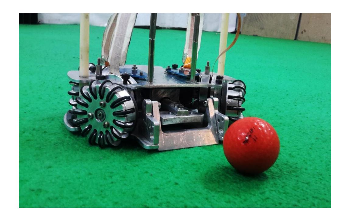
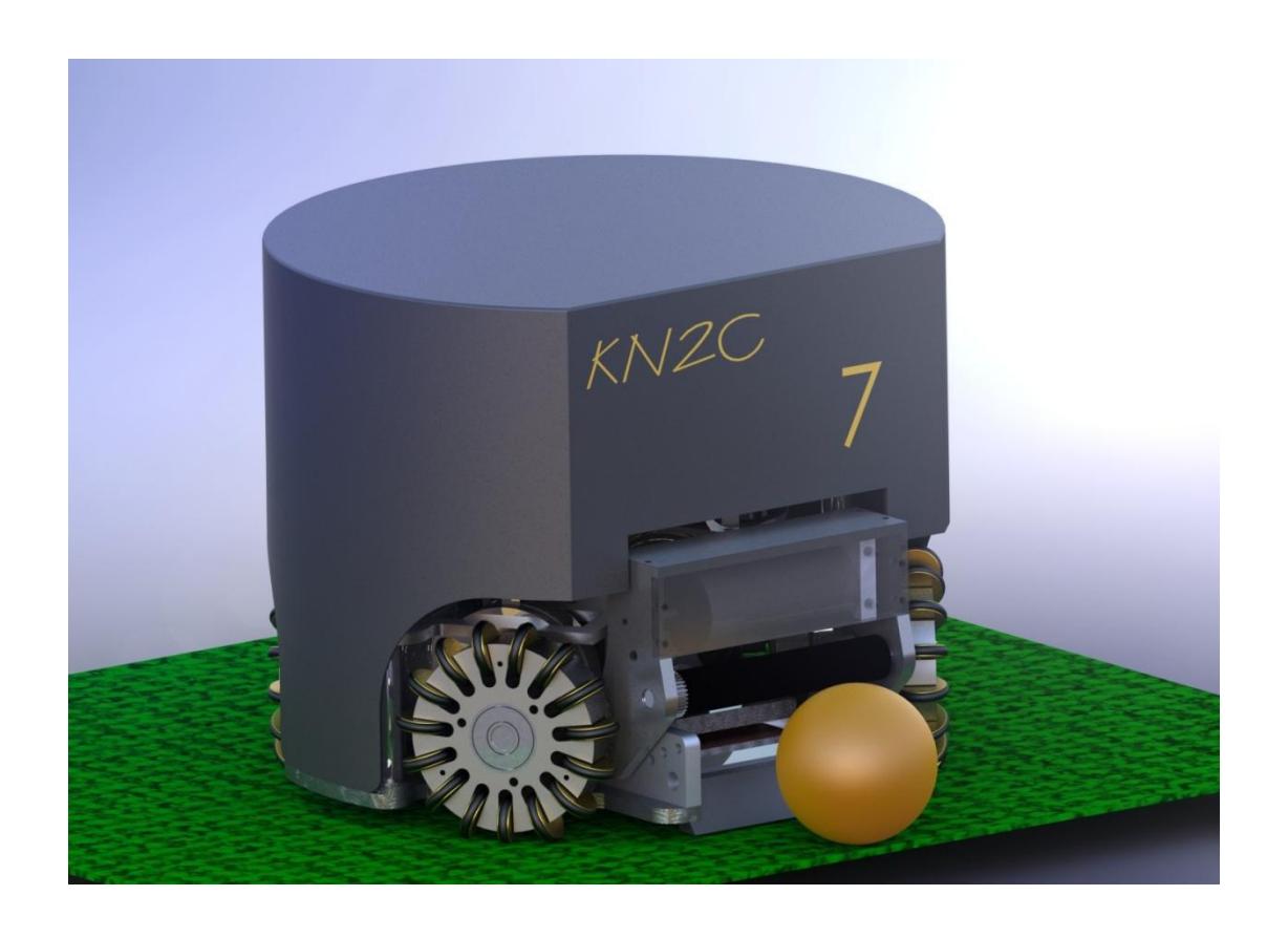
Since last year many changes have been made on mechanics. New Robots have 4 Maxon EC45 Flat motors. These motors are 12V, 4200rpm and 30W. Diameter of the motors is 45mm and their length (including the length of encoders) is 4cm. With these dimensions it was simple to place four motors in each robot. Motors Gears are placed inside the wheels with 8.3:1 ratio. Considering these, our robots are capable of moving forward up to 3.5 m/s.
This year, unlike last year, both direct and chip kicks are designed in the robots. For direct kick we used a solenoid with 8 round of 23AWG wire and for chip kick we used 6 round of the same wire. This way robots are able to kick the ball up to 8 m/s in direct direction and 2.5m distance with chip kick.
2.1 Arrangement of motors
How motors are arranged, is very important because 2 kick solenoids should be placed in the space between them.
3. Electronics
The proposed electronic system for KN2C robots is described in the following sections.
3.1 Main Board
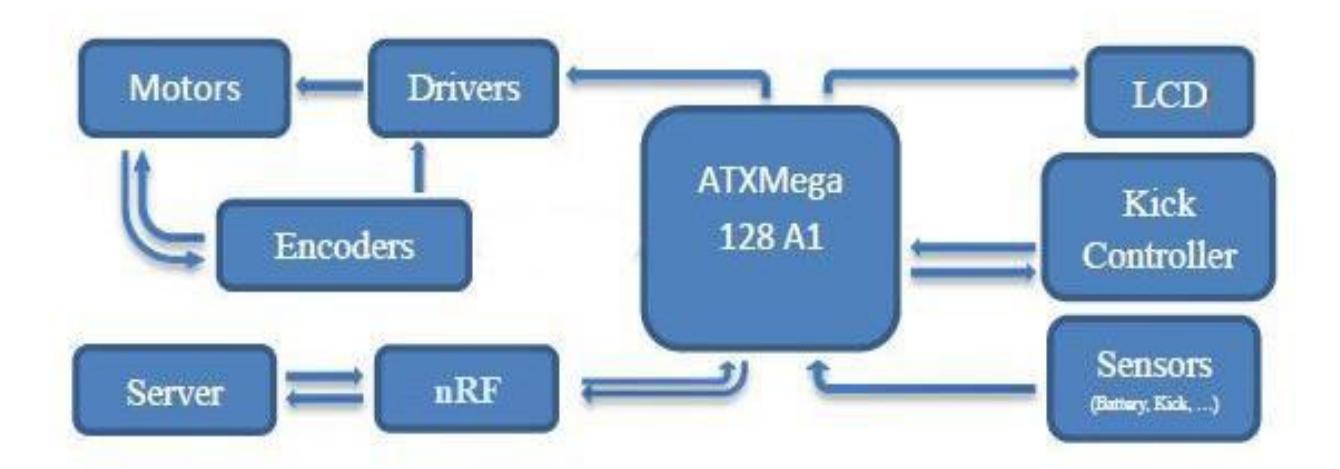
In each main board an ATXMega128A1 Microcontroller (from AVR Family) is used to process data in robots. This 8bit Microcontroller has a lowpower consumption. The internal architecture of this microcontroller is RISC, with 1MIPSPer MHz processing power and 32MHz operating frequency.
3.2 Motor Drivers
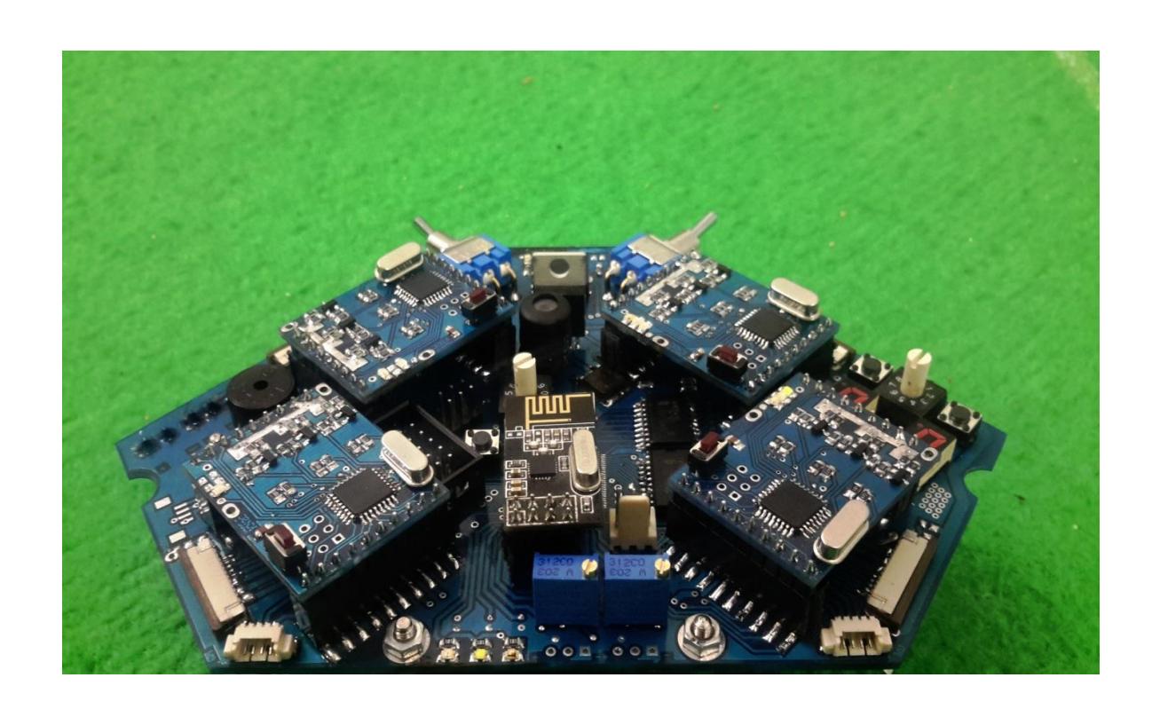
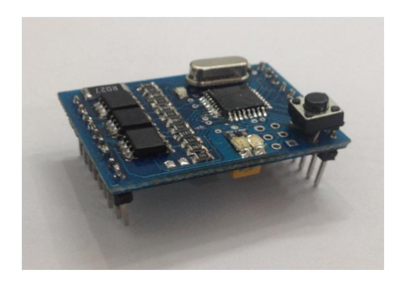
To Drive Brushless DC motors, inverter 3 phases circuits with ATMega88PA microcontroller is used. This circuit provide three square waves with 120 degree phase difference. These three waves provide torque in motors. In order to switch between phases, hall effect sensors are used that can determine the location of the poles of motors.
3.3 Wireless communication
nRF24L01P modules are used for wireless communication between computer and robots. Operation frequency of this module is 2.4GHz and could be changed in range of 100MHz. This module works in SPI communication protocol. In this communication, motors speed, kick speed and robot ID are sent from computer to robots and battery charges, kick sensor signals are sent from robots to computer.
3.4 Kick Circuit
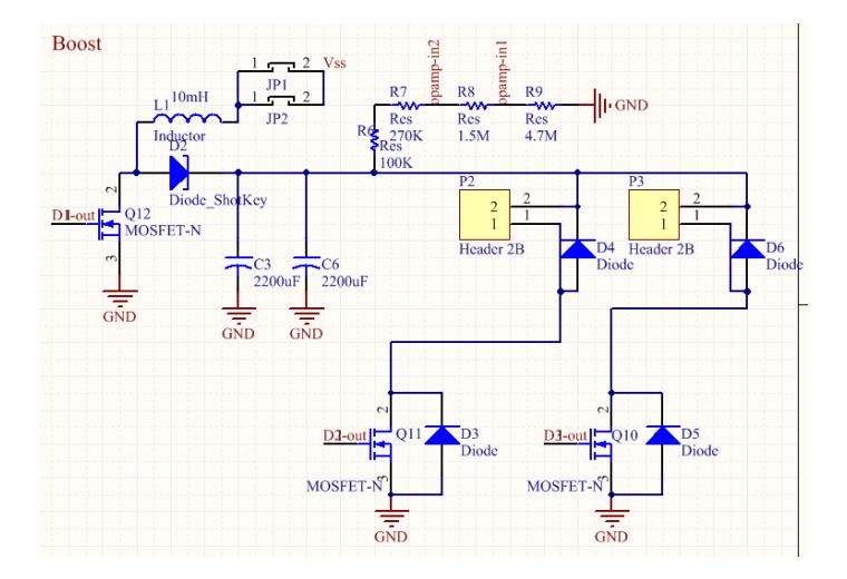
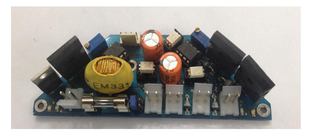
In kick circuit in order to achieve the proper speed, two parallel capacitors (200V, 2200uF) are charged to the desired voltage level using a Boost circuit. Then the microcontroller from the main board produces PWM wave to give the order of straight or chip kick. The maximum speed obtained is 8m/s.
4. Software
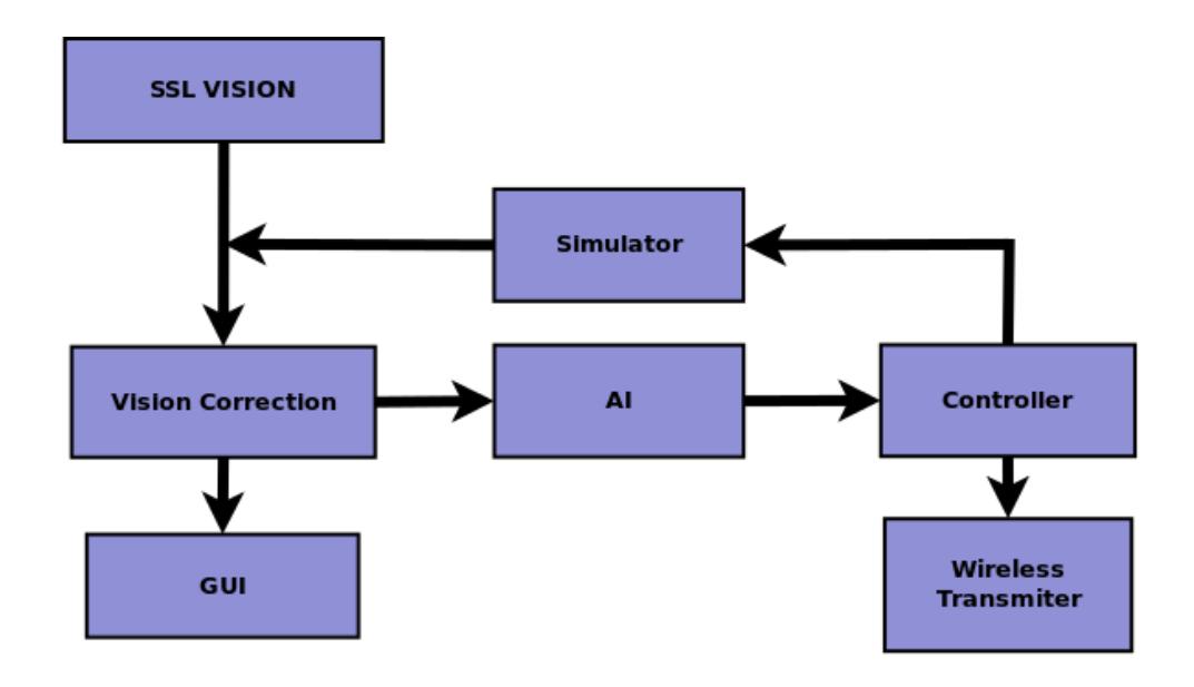
The proposed architecture is based on the chart below:
SSL Vision
This open source software is used for image processing.
Vision Correction
This section is used to correct data from Google Protobuf. Then it sends The corrected data, such as the position of the ball and position of the robots, to other parts.
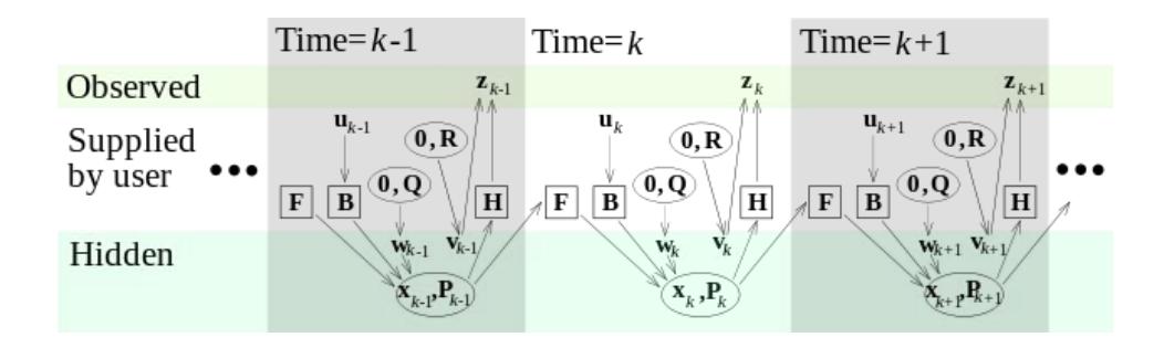
Kalman Filter
The Kalman filter, also known as linear quadratic estimation (LQE), is an algorithm that uses a series of measurements observed over time, containing noise (random variations) and other inaccuracies, and produces estimates of unknown variables that tend to be more precise than those based on a single measurement alone. this filter is used to correct the coordinates of robots and ball and also to measure their velocity. The important thing is to get the system state equation and to determine the process noise. For example camera noise could be calculated from variance of several data.
AI
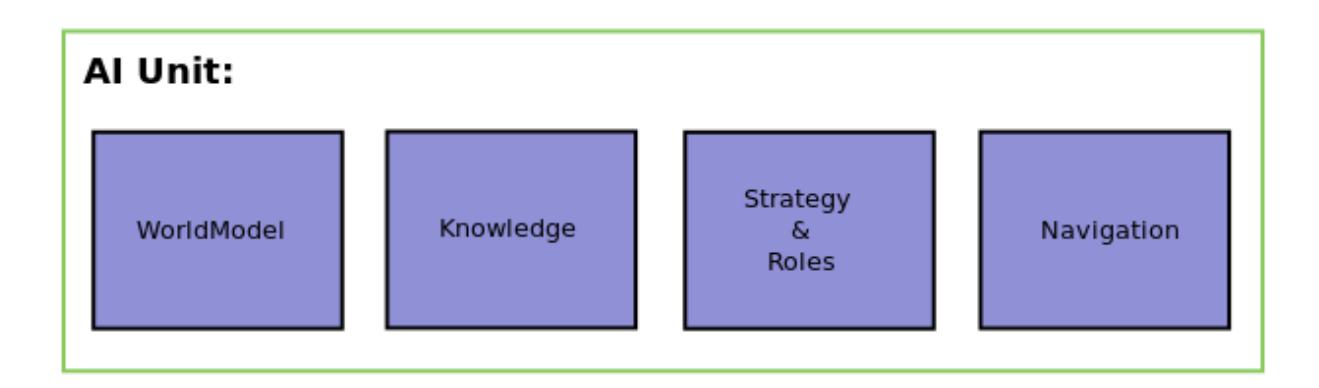
Core software and team algorithms are presented in this section. The main sections of team are based on the following:
World Model
Updated information about the players and the current state of game is in this section. These data are updated every 1/30 second.
Knowledge
By applying a series of computational algorithms on the raw data from SSL Vision and SSLRefbox some results such as the number of active players and finding the nearest player to reach a point are obtained. These data are stored in this part of the AI.
Strategy and Roles
The current structure of our team is that, a Role is considered for every player according to the position of the ball, Opponents and the team's strategy. Considered roles for players are as follows:
- Role_Goalie
- Role_CideBack
- Role_CenterBack
- Role_SideForward
- Role_CenterForward
Navigation
Two types of combinations are considered for movement of players in the field which is divided into two sections:
- Static Formation
- Dynamic Formation
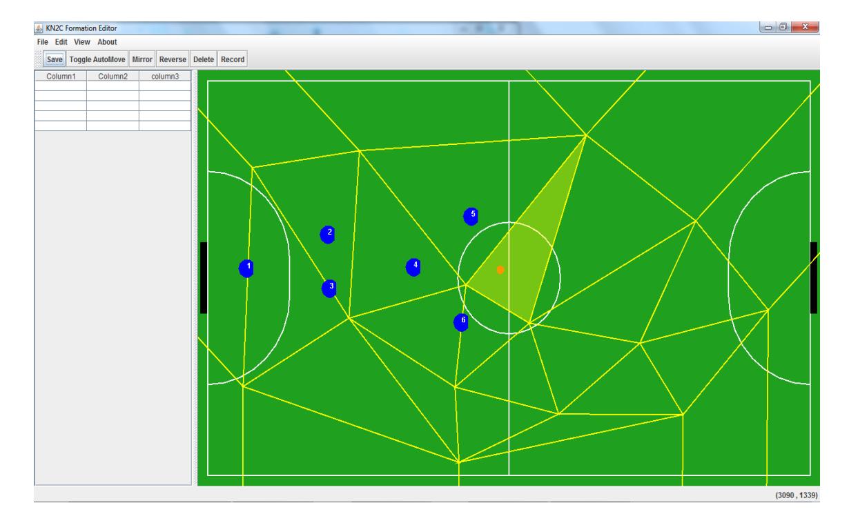
For Static Formation a software is designed and implemented by team that triangulate the field using Delaunay Triangulation algorithm. Then it sets a location for players according to the position of ball in these triangles. The designed software is as follows:
The RRT routing algorithm
This algorithm is designed for optimal search in non-convex and multidimensional spaces that, selects spots in successive stages in order to reduce distance of the expected path to reach the answer. This algorithm is used for routing paths containing hard constraints and obstacles. Therefore we decided to use this algorithm for robot navigation. The Pseudo Code is presented below:
$$G.INIT(q_{init})$$ $$for k = 1 \rightarrow K$$ $$q_{rand} \leftarrow RAND - CONF( )$$ $$q_{near} \leftarrow NEAREST - VERTEX(q_{rand}, G)$$ $$q_{new} \leftarrow NEW - CONF(q_{near}, \Delta q)$$ $$G.ADD - EDGE(q_{near}, q_{new})$$ $$return G$$
Controller
There are two control loops of type PI Controller in Robots. In the first loop using motion vector of each robot, robot motion speed is calculated by the computer. Then the calculated speed is sent to the robot. In robots the speed of each wheel is read by the encoder and compared with the desired speed, then the input of each motor driver is obtained by PID controller.
Simulator
Results from the AI, is tested in the grsim simulator.
This software written by the Persian team, also has the ability to produce output for Vision.
References
- Helios Fedit: http://en.sourceforge.jp/projects/rctools/releases/48791
- Valiallah Monajjemi, Ali Koochakzadeh, Saeed Shiry Ghidary, "grSim RoboCup Small Size Robot Soccer Simulator", to appear in: RoboCup 2011: Robot Soccer World Cup XV, 2011