MCT Susanoo Logics 2014 Team Description
Satoshi Takata, Yuji Horie, Shota Aoki, Kazuhiro Fujiwara, Taihei Degawa
Matsue College of Technology 14-4, Nishiikumacho, Matsue-shi, Shimane, 690-8518, Japan
Abstract Our robots and systems are designed under the RoboCup SSL 2014 rules in order to participate in the RoboCup competition in Brazil. This year, we improve the dribble device of the robot and the AI architecture. This paper describes them and other systems of the robots.
1 Team outline
The MCT Susanoo Logics consists of the members of Department of Control Engineering, Electrical Engineering, and Information Engineering of Matsue College of Technology (Kosen). Our Robots with four Maxon 30 watts flat motors were totally designed by the team members and manufactured in the MCT factory. Electrical circuits boards were designed with Eagle PCB software and cut with Mits PCB Milling System. The artificial intelligence system of the robots was programed by C++ and C#.
The team has participated in the RoboCup SSL in Japan since 2011. Last year, the team participated in the RoboCup SSL 2013 in the Netherlands. That was our first world competition.
This year, we redesigned the dribble device to improve the success rate of the ball trap, and the AI architecture to shorten the developing time.
2 Hardware outline
Figure 1 shows the MCT Susanoo Logics' 2014 model robot.
The dribble device is the most important modification point of this year. The absorption method of the kinetic energy of the ball was modified from the vertical motion of the dribble bar of the dribble device to the rotary motion of the dribble device (Fig. 2). The modification improves the success rate of the ball trap. We changed the structure of the dribble device to minimize the assembly time (Fig. 3).
To prevent from the fiber or the field, the shape of the bottom plate was modified to cover the gear of the wheels (Fig. 4).
The nylon Omni wheels of the 2013 model were not robust. We changed the material of the wheel to duralumin. Table 1 shows specifications of the robot.
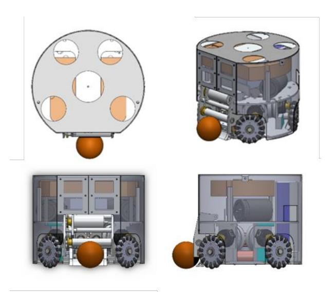
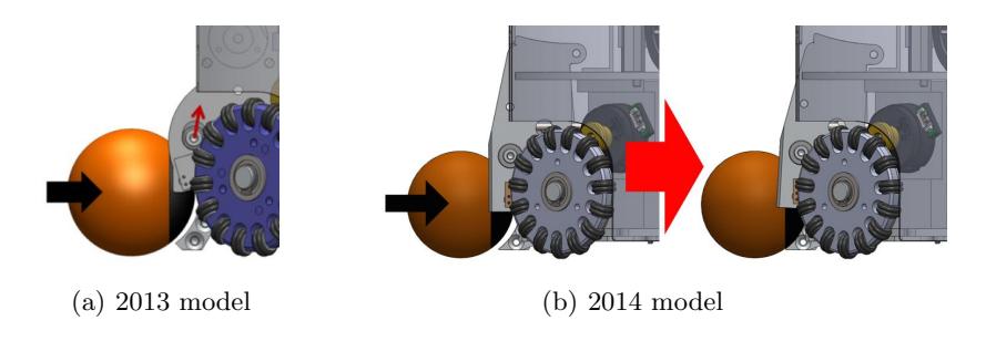
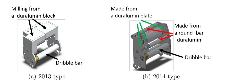
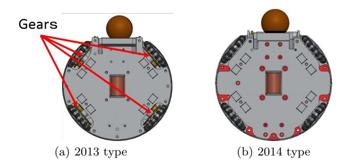
Table 1: Specifications of the robot
| Height mm | : 148.5 |
|---|---|
| Diameter mm | : 177 |
| Weight kg | : 2.5 |
| Maximum robot speed m/s | : 3.0 |
3 Electronics
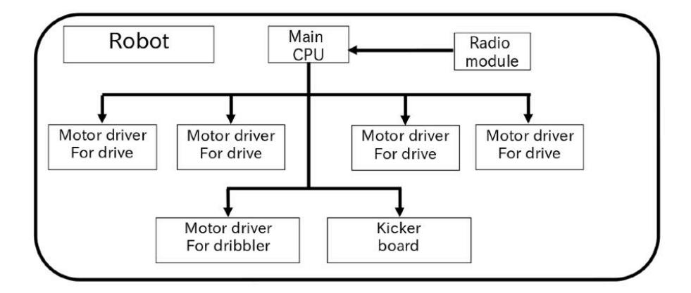
A schematic block diagram of the machine is shown in Fig.5.
Battery
Electrical energy is supplied to the circuit boards by a 14.8 V 4-cell LiPO battery.
Main board
A microchip (dsPIC33FJ32GP202) is implemented to the machine as the main CPU. The main CPU clock is internal oscillator with a frequency of 80 MHz.
Communication
Communication from the AI to each machine is via a 2.4GHz band radio module Xbee 802.15.4. The vision system sends data every 1/60 th of a second. Therefore, the communication time length has to be shorter than 1/60 th of a second. The Xbee's baud rate is set at 115200. It means that the AI sends data to all machines in 8 ms. The AI sends instruction data to the machines by broadcast. Instruction data include machine velocity, angular velocity and command data. Command data is to control the kicking and dribbling devices.
Ball sensor
The ball sensor senses when a ball comes in front of the machine and indicates the possibility that the machine can kick the ball. Infrared LED and photo-transistor pair are implemented in front of the machine.
Velocity calculation for each wheel
Each machine has four omni-wheels. The AI sends machine velocity as instruction data. Therefore, the machine must calculate the velocity for each wheel from machine velocity. The main CPU calculates the velocities and sends the data to each motor driver board. We apply I2C to communication between the main CPU and the motor driver boards.
Power supply
The main board has a voltage converter for power supply. A DC-DC converter V-INFINITY V7805-1000 converts the 14.8 V voltage from the battery to 5V. The 5 V supply is used by the MOS-FET gate driver IC and rotary encoder. A linear regulator converts part of the 5 V supply to 3.3 V to power the dsPIC and radio module XBee.
4 Kicker board
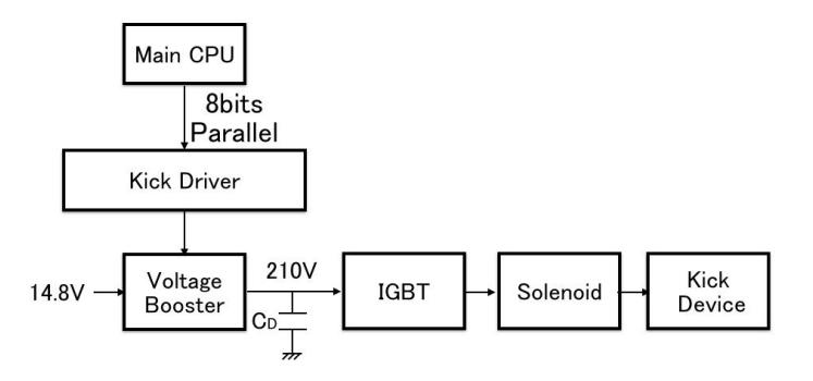
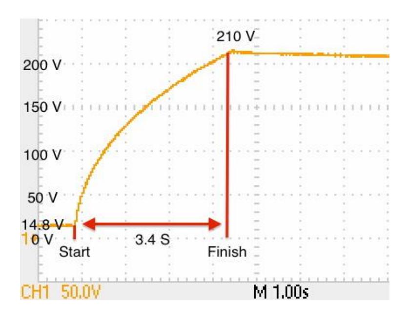
Figure 6 shows the diagram of the kicker system. The system consists of a main CPU, a kick driver, a voltage booster, a drive capacitor (CD) of 2 * 2200 uF, a IGBT, a solenoid, and a kick device. The voltage booster boosts the battery voltage of 14.8 V to 210 V and charges the drive capacitor (CD). The IGBT drives the solenoid to kick the ball with the kick device. The voltage booster charges the drive capacitor (CD) from 14.8 V to 210 V within 3.4 seconds (Fig. 7). The voltage of the drive capacitor (CD) after the kick is usually 160 V, thus the recharge time is 1.2 seconds. A capacitor charger (Linear Technology LT3750) is used for the boost converter. For adjusting the strength of the ball kick, the main CPU controls the gate-on time of the IGBT for the drive capacitors.
5 Motor control
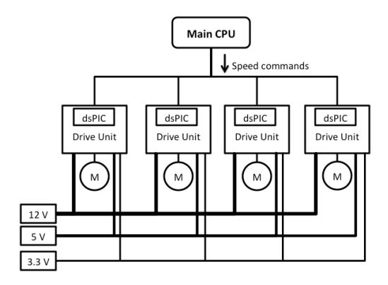
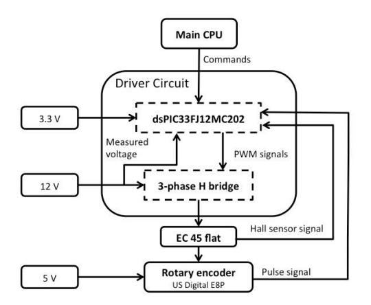
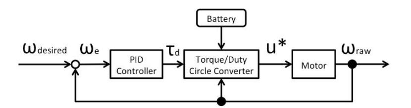
Figure 8 shows the control system of the MCT susanoo logics' robot. Where, M is the motor. The system have 4 Motor drive units for brush-less DC motors. The main CPU receives speed vector of the robot from AI computer, and calculates 4 motor speeds.
6 Robot control method
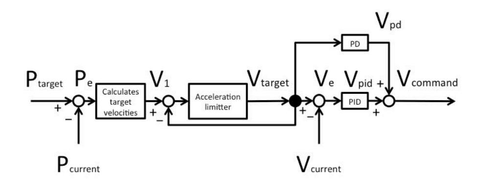
Figure 11 shows the velocity calculater. The AI computer calculates the target position. The velocity calculater decides the speed vector of a robot from the target position Ptarget, current position Pcurrent, and current robot's speed vector Vcurrent.
7 AI architecture
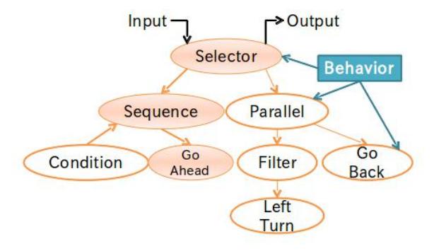
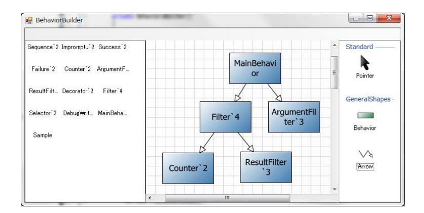
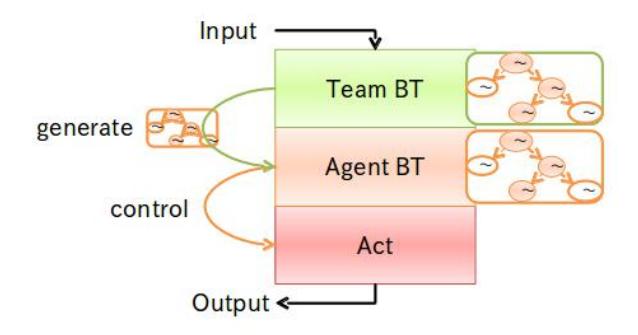
Our AI is mainly composed of Behavior Tree and STP (skills, Tactics and Play). Behavior Tree is a system that divides AI behavior into units named 'Behavior' and a tree of Behavior nodes controls the AI. Conceptual diagram of Behavior Tree is shown in Fig. 12.
References
- Krit Chaiso, Kanjanpan Sukvichai : Skuba 2011 Extended Team Description, Kasetsart University, Thailand, 2011.