NEUIslanders 2014 Team Description Paper
Prof. Dr. Rahib H. ABIYEV, Assist. Prof. Dr. Irfan GUNSEL, Nurullah AKKAYA, Ersin AYTAC, Murat ARSLAN, Fatih EMREM, Gorkem SAY, Ahmet CAGMAN, Senol KORKMAZ, Ilker DAGLI, Mustafa ARICI
Department of Computer Engineering; Department of Mechanical Engineering; Department of Electrical and Electronic Engineering
Abstract This paper describes a detailed descriptions of NEUIslanders robotic team of small size league in RoboCup 2014. The important parts of mechanical, electronic and software design are described. The Robots are designed under the rules of RoboCup 2014 rules. The improvements that has been done on robots are presented. These are related to the change and new design of kicking and dribbling mechanism, electronic design of kicker system and improvement of navigation system of robot
1. Introduction
NEUIslanders is an interdisciplinary team of students at the Near East University. The team is currently seeking qualification for RoboCup 2014. Since last year, it has made significant developments of its team of autonomous soccer playing robots. This paper will outline the progress in implementation of the current model of robots.
NEUIslanders robot system consists of three major components: the robot hardware, electronics and control the software. The software makes strategic decisions for the robot team by using information about the object positions from the vision system.
In Hardware section, we give the details of the mechanical parts our robots. The basic mechanical components of the robots are described in detail.
In Electronics section, we give the details of our electrical design on the robots. We are giving the basic information on how our electrical part is working.
In Software section, we give implementation details of our control software. These include the software for decision making system, path finding and motion control, finally Conclusions are given in the last Section.
The NEUIslanders robotic team is improved every year. Since 2012 the team is taking part in RoboCup Small Size League. This year following improvements are added to the robot;
- Improvement of the dribbling and kicking device
- Improvement of the dribbling and kicking electronic circuit
- Improvement of the wheel motors electronic circuit
- Improvement of the path finding algorithms
2. Mechanical Design
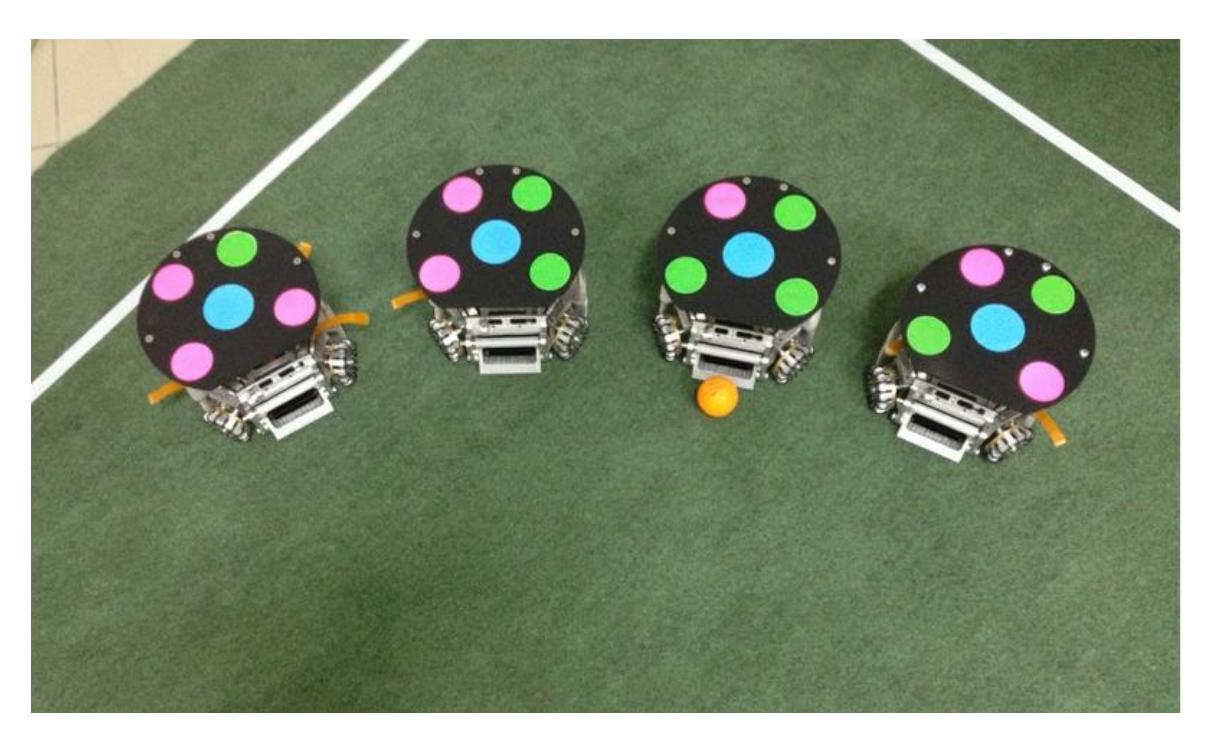
The mechanical designs and parts of our robots have some minor changes this year. All of our mechanical parts are manufactured in high precision CNC machines with a micron accuracy. The robot diameter is 175 mm and height of 145 mm.
2.1. Chassis
We are using the same 3mm thick 7075 aluminium for the chassis. Wheel orientation is dramatically effecting the robots speed and acceleration. After calculations we figure out that 45 degrees at the rear and 33 degrees at the front wheels with respect to the horizontal axis is the best orientation that fits our robots.
2.2. Omni-Wheels
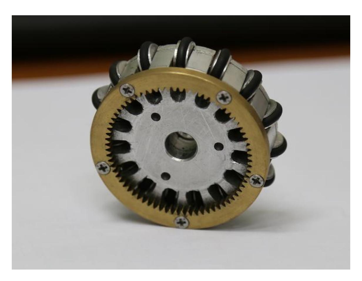
Wheel hub has an inner canal for the ring to add rollers which are 10 mm in diameter. The are 15 rollers on our omni wheel. The wheel cover is just to cover the inner part of the wheel. Also last year we used external gear to couple with the pinion gear on the motors. This year we are using internal gears which are placed on the back side of the wheel with 72 teeth on them. The pinion which is going to couple with this inner gear has 20 teeth on them. Both of the gears are manufactured from brass.
2.3. Motor Mounts
We are using 3 mm 7075 aluminium for the motor mount and our calculations shows us that the bending moment is higher. Also to take the center of gravity lower 10% of the motor is going through a hole in chassis. We housed the wheel shaft at motor mount last year but that caused us some problems. This year we changed the bearings position to the wheel hub and used ceramic bearings, this gave us %10 performance improvement.
2.4. Kicker
Chip kicker has a custom made flat solenoid, a steel plunger placed in the solenoid and like last years design the plunger hits a swing which has 45 degrees on the bottom. The other kicker has a round solenoid. The kicker is made of 5 different parts. An e clip placed on the back to limit the kicker made from aluminium. In the middle only a very small part is made from steel which is inside the solenoid. The front is consists of 2 different parts. First an aluminium part is connected to the steel rod. The front part is manufactured from a flat part 7075 aluminium and it has a little curvature to center the ball for kicking directly to the target. As an improvement this year we can hit the ball in very large range of speeds from 0.1m/s to 8m/s.
2.5. Dribbler
Up to this year we did not have a dribbling unit. This year we bought Maxon EC-16 30Watt motors and couple them with 16 teeth gears with the dribbler. We are still waiting for the Maxon motors meanwhile we added brushed motors to test our dribbling unit. Dribbler is made of 6062 aluminium can spin up to 10000rpm.
3. Electronic Design
The electronic circuits of robots includes main control units of wheel's motors, dribbler's motor and kicking mechanisms. These control units include the main CPU, power supply circuit, wireless communication module, ball detecting circuit and dribbling motor controller, and motor driver.
3.1. Battery
On our robots we have two 2650 mAh high discharge 35-70C lithium polymer batteries are connected in series. Batteries are powering the robots kicking device, micro controllers, and all motors. These two batteries are giving enough power to play two games in a row. The batteries are wrapped in li-po safes to prevent from any fire or explosion accidents.
3.2. Motors & Motors Drivers
In each robot we have four 36V 30Watts 3 phase brushless DC Maxon Ec-45 Flat motors. Each motor is connected to Maxon 1-Q EC Amplifier DEC Module 50/5 motor drivers. We are using these motor drivers to get the maximum motor output.There are three hall sensors which are located 120 degrees apart in the motor. The analog output of the hall sensors are connected to the micro controller to control the position and revolution of the DC motor and send the desired power to the DC motors.
Three signals are send to the each motor driver. One is for controlling the motor speed with a PWM signal. The other signal is to determine forward and back control. And the last signal is for controlling the brakes.
3.3. MicroControllers
There are two micro-controllers in our robot one is ATmega328P and the other one is ATtiny85.
ATmega 328P is controlling the four motors, dribbler and kickers. This micro-controller is connected to XBEE Pro which communicates with RF to the main computer. ATtiny85 is working with the kicker circuit and used for voltage amplifying. This microcontroller is reading the capacitors voltage and creating PWM signal to create the constant voltage to charge the capacitor.
3.4. Kicking Circuit
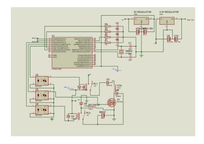
The amplifying circuit is using high speed mosfet to drive it with PWM to charge a 2200uF 250V capacitor in 2 seconds. The solenoid to kick the ball is controlled by ATmega 328p micro-controller.
To kick the ball in various speeds there is dimmer circuit. The micro controller is sending a digital signal to dimmer circuit. The dimmer circuit gets ready the speed of the kick and waits for the micro-controllers kick command.
3.5. Dribbling Circuit
3 phase DC Maxon EC-16 15Watts are used for dribbler. There are six mosfets to drive this 3 phase DC motor. When the robot gets closer to the ball the dribbling circuit gets the signal from micro-controller to keep the ball right in front of the robot and makes the robot to kick straight and with maximum power.
4. Software Design
(empty)
4.1. Structure of control system of the robots
The detail structure of the robot soccer control system designed in this paper is given in Figure 4. Host computers tracks the world using high speed overhead cameras. SSL vision by using the camera processes the map of the world and obtains the coordinates of soccer robots and balls then sends them to the computers. All communication from the SSL-Vision system to the clients is performed via network by UDP Multicast. All datapackets are encoded using Google Protocol Buffers. In order to track the world in real time, the data is sent every 1/60 of a sec. Tracker module captures this data stream off the network and converts it into a data structure which will be used by decision making (DM) module. DM block using this data, makes strategic planning of soccer robots. Here problem is using the current coordinates of soccer robots and goal, to make strategic planning and implement control of each robot. The BT based control of the robot soccer is used in DM block.
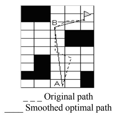
After selecting certain behaviours, in order to move the holonomic robots to their new positions, the path finding block starts to look for a path for each robot that will take them to their target locations. Path finding algorithm is run for each robot to find their feasible paths. The used path finding algorithm is given in section 3.
4.2. Design of Path Finding Procedure
One of more used algorithm that can be used for path finding purpose in mobile robot navigation in fast dynamic environment is a Rapidly-exploring random tree (RRT) algorithm. RRT algorithm is designed for efficiently searching nonconvex, highdimensional search spaces. RRTs incrementally reduce the expected distance of a randomly-chosen point to the tree. RRTs can be incorporated into the development of a variety of different planning algorithms.
The key idea of RRT is to bias the exploration toward unexplored portions of the space by sampling points in the state space, and "pulling" the search tree toward them. The algorithm proceeds by growing a single tree from the initial configuration until one of its branches encounters the goal state. It attempts to extend the RRT by adding a new vertex that is biased by a randomly-selected state.
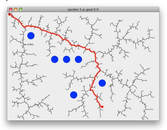
Following procedure demonstrates RRT path finding on a 2D surface. Starting at the goal, search tree will rapidly expand through the space towards the goal. RRT-Plan pretty much summarises all of the above steps, choose-target either picks a random point on the map or returns the goal, nearest returns the closest point on the tree to the chosen target. explore then checks if we can extend the tree towards the point or not. epsilon is the distance we extend the tree by and pGoal is the probability of goal used to guide the search towards the goal. RRT-Plan returns when we add a point to the tree that is closer than epsilon to the goal,
Inputs for the RRT-Plan function are,
World- map of the environment containing size and obstacle locations
Start- start position
Goal- goal position
Tree- RRT itself, tree that describe a map of parent nodes to child nodes.
Epsilon- the amount that the tree is expanded at each explore call
The following procedure demonstrates RRT planning algorithm (Fig.1),
function RRT-Plan(world,start,goal,epsilon p-goal,tree)
 target ← chooseTarget(world, pGoal, goal)
 nearest ← nearest(tree, target)
 if( distance(nearest,goal) < epsilon )
 return tree
 else
 explored ← explore(world, nearest, target, epsilon)
 if (explored != nil )
 addNode(tree,explored)
 RRT-Plan(world, start, goal, epsilon, p-goal, tree)
function chooseTarget(world, pGoal, goal)
 p ← UniformRandom in [0.0 .. 1.0]
 if 0 < p < pGoal
 return goal;
 else
 return randomState(world)
function nearest(tree,target)
 point ← first(tree)
 for each node in rest(tree)
 if distance(node, target) < distance(point, target)
 point ← node
function explore(world, u, v, epsilon)
 explored ← extend(u, v, epsilon)
 if checkCollision(world, explored) = false then
 return explored
 else
 return nil
As shown in figure 1 the inputs for RRTs are map of the environment, start and goal position, RRT tree and the amount it is expanded at each step. During the run of the algorithm, at the first stage, "chooseTarget" determines where to explore the map by randomly selecting a point on the map giving bias towards the goal, with probability pGoal, that expands the tree towards the goal minimising the objective function distance. Here to choose a target uniformly distributed points are generated using random number generator. Then the algorithm determines the nearest node using "nearest" procedure. If the distance between the node and target position is less than the distance between generated point and target position then the generated point is selected as new node where tree will be explored. In each iteration when the new node is selected, the distance between this nearest point and goal position is tested. If this distance is less than the required small value epsilon then the tree is returned as result of RRT algorithm. Otherwise the three is extended and explored. During extension of the tree the presence of obstacles are tested. In the case of presence of obstacles the tree is not extended toward to that direction. Otherwise the selected tree will be extended towards the chosen target and RRT algorithm will be iterated until goal position is reached.
5. Conclusion
In this document, we have shown the current development stage of the NEUIslanders SSL robot soccer system. We have emphasised the major changes in our electrical design and software architecture. Our new design will enable the system to react quickly to the changes in the game state, as well as perform more efficiently than the design we have developed in 2013. The strategy system still needs some more improvements.
References
- Borenstein, J., Everett, H. R., Feng, L., Navigating Mobile Robots: Systems and Techniques. A K Peters, Wellesley, MA.. 1996
- J. Borenstein and Y. Koren. Real-time obstacle avoidance for fast mobile robots in cluttered environments. In Proceedings of the IEEE International Conference on Robotics and Automation,1990.
- J. Borenstein and Y. Koren. The vector field histogram- fast obstacle avoidance for mobile robots. IREE Journal of Robotam and Automation, 1991.
- Rahib H.Abiyev, Nurullah Akkaya, Ersin Aytac. Control of Soccer Robots using Behavior Trees. ASCC, June, 2013, Istanbul.
- Rahib H.Abiyev, Nurullah Akkaya, Ersin Aytac. Navigation of Mobile Robot in Dynamic Environments. IEEE International Conference on Computer Science and Automation Engineering CSAE 2012, Zhangjiajie, China, May 25-27, 2012,
- Rahib H.Abiyev, Senol Bektas, Nurullah Akkaya, Ersin Aytac. Behaviour Trees Based Decision Making for Soccer Robots WSEAS March 2013 Lemesos, Cyprus
- Rahib H.Abiyev, Dogan Ibrahim, Nurullah Akkaya, Ersin Aytac. Behaviour Tree Based Control For Efficient Navigation of Holonomic Robots International Journal of Robotics and Automation ACTA Press January 2014