Owaribito-CU 2014 Team Description
Asahi NAGAO, Motoki UNO, Noriyuki UEDA
Faculty of Engineering, Chubu University, Japan
http://www.robocup.org/ · http://www.robocup.or.jp/ · http://kiyosu.cs.chubu.ac.jp/SSLJapan/
Abstract This paper presents the description of the Owaribito-CU Small Size League team as it stands for the RoboCup 2014. The paper contains descriptions of the mechanical, electrical and software modules.
1. Introduction
Owaribito-CU is an interdisciplinary team of undergraduate students at the Chubu University. The team has participated in RoboCup Soccer Small Size League since 1999. In this paper, we described our hardware and software architecture.
2. Hardware Architecture
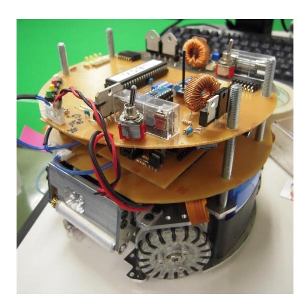
We have improved some points of our soccer robots for RoboCup 2014. These robots are equipped with a holding device and kicking device. Four omniwheels are used for the driving mechanism; they aid in realizing omnidirectional motion. The hardware specifications are listed in Table 1. The robot is shown in Figure 2.
Table 1. Hardware specifications of Owaribito-CU 2014 Robots
| Height | 148mm |
|---|---|
| Maximum diameter of projection | 178mm |
| Maximum ball coverage | 19% |
| Gross weight | 2200g |
| Body frame material | Polycarbonate |
| Main microcomputer | PIC16F1939 |
| Motor control | dsPIC 30F4012 ×4 |
| Wireless communication | Xbee |
| Motor | Maxon EC45 ×4 |
| Power supply | Lithium Ion 12V, 1100mA/h ×2 |
| Capacitor for kicking devices | 200V, 2200uF ×2 |
From among the research that was worked on this year, this text describes the improvement of the control circuit board.
3. Details of the Main Board
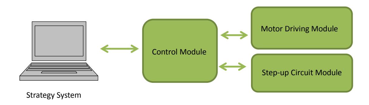
The main board is composed of three modules (step-up circuit module, motor driving module and control module). Overview of the main board is shown as a diagram below.
4. Improvement of the Step-up Circuit Board for Kick Device
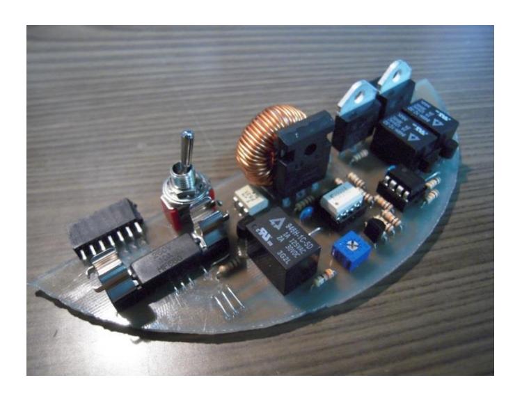
Figure 4 and Table 2 shows the external and the detailed data of the kick device. The driving source of this kick device is a solenoid as well as most other robots of RoboCup small-size robot league. The aim of this project is the improvement of miniaturization and reliability for kick device. Figure 4 shows the Step-up Circuit Board.
4.1. The Problems of Kick Device and Solutions
The problems of the current type of kick device are outlined below:
- We had separated step-up circuit board and the main control board. As a result wasteful space was remained.
- We had used a timer IC as a measure of the timing of the charge and discharge. There is a danger that the battery and circuit to fail due to overcharge.
To solve the above-mentioned problems, a new kick device is developed in this research based on the following ideas.
- We combined step-up circuit board and the main control board.
- In order to prevent overcharging, it is arranged to monitor the voltage of capacitor using the comparator.
- We used a photo-coupler between the step-up circuit and control circuit in order to prevent malfunction due to the switching noise during charging.
Table 2 shows the about details of new circuit for kick device.
Table 2. Details of New Circuit for Kick Device
| Power Supply | Lithium Ion 12V, 1100mA/h ×2 |
|---|---|
| Capacitor | 200V, 2200uF×2 |
| Operational Amplifier | LM358N |
| Step-up Voltage | 200V |
| Charging Time | 2.5sec |
5. Remake of the Motor Driving Circuit Board
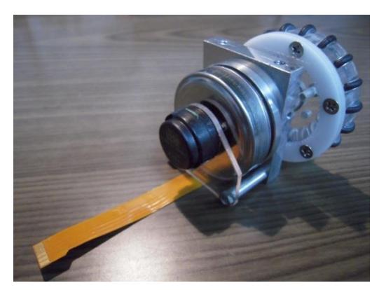
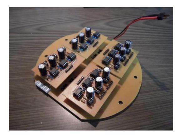
We are using a brushless motor (MAXON: EC45). Motor module shown in Figure 5. The motor driving circuit board is generating the three-phase pulse signals necessary to drive the brushless motor. As a result of changes to the brushless motor from the DC motor we have succeeded to get higher torque and to eliminate wasteful space. The motor driving circuit board is shown in Figure 6.
6. Remake of the Control Board
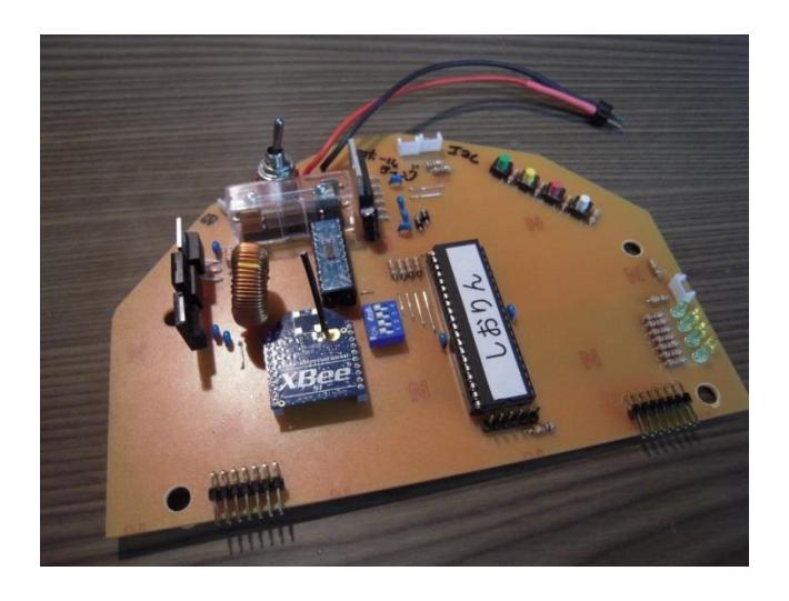
We are using PIC16F1939 for main microcomputer. The control board is shown in Figure 6. We are using the Xbee modules to communicate with the strategy system. We reduced number of connectors using the I2C protocol between modules. As a result, problems caused by the poor contact of the connector have decreased.
7. Software Architecture
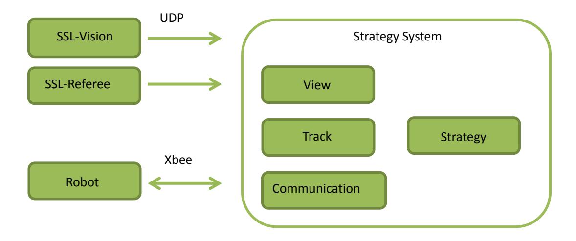
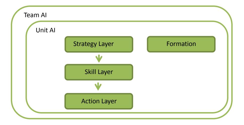
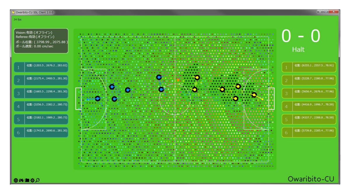
The overview of our software system is shown as a diagram below.
8. Remake of the Strategy
The new strategy is shown in Figure 8. To achieve a more dynamic strategy, the new strategy, implements Goal-Oriented Action planning (GOAP)[6][7]. GOAP has hierarchical structure, and it consists of three layers (strategy layer, skill layer and action layer). The team AI is managing of the Position AIs (FW, MF, DF, GK) in response to the tactical situation. The Unit AI is managing of the robot and communication between robots. The decision-making architecture known as Goal-Oriented Action Planning (GOAP) offers dynamic problem solving, which is a key ingredient in crafting AIs which appear to understand their environment and react in a logical manner. In each layer, is chosen the most appropriate action in accordance with the situation.
9. Conclusion
We have described the specifications of our 2014 version robots. Furthermore, we have described several topics from the developments of this year. We have developed fully new control circuit board. It realized to introduce the brushless motors, and higher torque was obtained. New circuit board also contributed to eliminate wasteful space on the board. We have changed the microcomputer from Renesas H8/3052F to Microchip Tech PIC16F1939 which has sufficient features in the control circuit board. To make the strategy system better, we have constructed a new strategy and GUI program to introduce variety of new strategies.
It is necessary to combine various techniques like mechanics, circuits, control, AI with a certain level, in order to operate a robot system stably. Then we will work to strengthen the entire system to keep a balance of both hardware and software. We are also looking forward to share experiences with other great teams around the world.
10. Acknowledgement
The paper is the product of longstanding obsession with the work. We are pleased to acknowledge the considerable assistance of Prof. A. Okazaki. Thanks are due to my many colleagues with whom we have developed our robots together.
References
- http://www.robocup.org/
- http://www.robocup.or.jp/
- http://kiyosu.cs.chubu.ac.jp/SSLJapan/
- Yasunori NAGASAKA, Morihiko SAEKI, Takuya SOGO, Shoichi SHIBATA, Hironobu FUJIYOSHI, Takashi FUJII, Yoshiyuki TANAKA, Seiya ISHIHARA, Masafumi JYOUO, Hiroyuki MIZUGUCHI, Takumi ADACHI, Takahiro ITOH, Syogo KUSATOMI, and Shinya SUZUMURA, "Owaribito-CU 2009 Team Description", 2009
- Yasunori NAGASAKA, Morihiko SAEKI, Takuya SOGO, Shoichi SHIBATA, Hironobu UJIYOSHI, Takashi FUJII, Yoshiyuki TANAKA, Masafumi JYOUO, Takumi ADACHI, Masaki ITO, Kazuhiro SUZUKI, Kazuo TAUCHI, Chikara INUKAI, and Alfred EBADE EFOSA, "Owaribito-CU 2010 Team Description", 2010
- Steve Rabin, "AI Game Programming wisdom", Charles River Media, Massachusetts, 2002
- Orkin, J, "Aget Architecture Considerations for Real-Time Planning in Games", AIIDE 2005, 2005