AUT-PARSIAN: Team Description for Robocup 2014
Alireza Saeidi, Mohammadhossein Malmir, Mohammad Mahdi Shirazi, Mohammed Behbooei, Shahin Boluki, Masoud Kazemi, Seyed Mehdi Mohaimanian Pour, Parnian Ghanbari, Saeed Jamshidiha, Parisa Dajkhosh, Amin Zahedi
Electrical Engineering Department Amirkabir Univ. Of Technology (Tehran Polytechnic) 424 Hafez Ave. Tehran, Iran
Abstract This is the team description paper of the Small Size Soccer Robot team "AUT-PARSIAN" for entering the Robocup 2014 competitions in Brazil. In this paper we will represent our robots' current design in mechanical, electrical, control and software engineering. Improvements and developments like new communication system, motor drivers, processor, control system and enhancements in predefined plays, a high speed positioning evaluator will be discussed in detail.
Introduction
"AUT-PARSIAN" small size soccer robots team, founded in 2005, is organized by electrical engineering department of Amirkabir University of Technology. The purpose of this team is to design and build small size soccer robots team compatible with International Robocup competition rules as a student based project.
We have been qualified for eight consequent years for RoboCup SSL. We participated in 2008, 2009, 2010, 2011, 2012 and 2013 RoboCup competitions. Our most notable achievements was AUT-PARSIAN's first place in RoboCup 2012 SSL's Passing and shooting technical challenges and Robocup 2013 SSL's Navigation challenge. Our team's name is changed due to the fact that the parsian small size soccer team and the AUT soccer simulation team have started a joint collaboration under the name of AUT-Parsian. In this paper we first introduce our robots' Mechanical design (section 2). Our new electrical design will be discussed In section 3 and control system and software will be covered in section 4 and5.
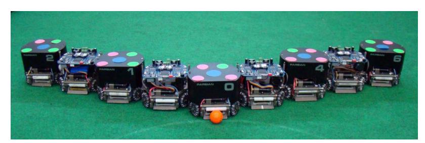
Mechanical Design
In this section we introduce our robot's mechanical design which we have been working on since RoboCup 2011. Our current (2014) robots' mechanical design was described in detail in our 2013 extended team description paper [15].
The mechanical design of these robots was not significantly changed from the past year and just we maintenance and remanufactured in some parts.
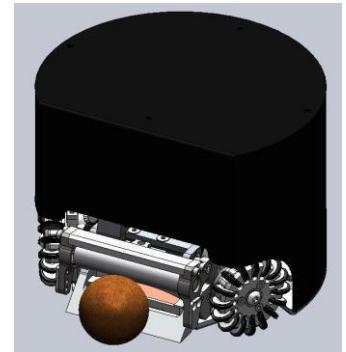
Robot's specification
| Robot Diameter | 178 mm |
|---|---|
| Robot Height | 138 mm |
| Ball Coverage | 19 % |
| Max Linear Velocity | 3.9 m/s |
| Weight | 2.0 kg |
| Maximum kick speed | 15 m/s |
| Limited kick speed | 7.5 m/s |
| Maximum chip kick distance | 7.0 m |
| Maximum ball speed catching | 6.0 m/s |
Main Structure and Driving System
In this section we express some information about mechanical structure that consists of plates, columns, fasteners, motors and wheels. The most practical Material of the structure is 7075 Aluminum alloy and in some cases we have used steel, polyamide and etc. Our robots have 4 Omni-directional wheels and Each wheel is driven by a Maxon EC-45 30w brushless motor. Power transmission system of the robots is summarized to a pair of internal and external gears which connect motors and wheels together.
Ball handling systems
Our robots use different mechanism for handling the ball. Kick/chip system and dribbling mechanism are the main components of the ball handling systems which have improved and optimized over the last 3 years.
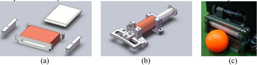
Kick/chip system of robots is composed of a mechanical structure and a solenoid that each one is optimized with the simulation analysis and experimental tests.
In this part, solenoid is a connection between the mechanical structure and electric charge board, So this optimization is a balancing between the hardware components. Dribbling system is also a practical ability in robot that with this the robot can absorbs and conveys the ball
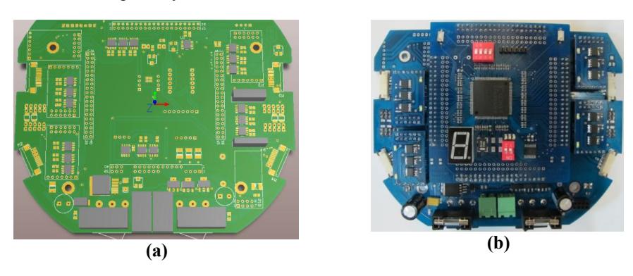
Electrical Design
Test Bed
A test bed platform was designed to satisfy the need for observation of the effects of a single parameter on the whole system, comparison of different modules, and test, evaluation and optimization of every part of robots' electronics.
The test bed board (figure. 5) is consisted of a stabilized power source that generates 5v, 3.3v, 2.5v and 1.2v, I/O ports (UART, SPI, USB and J-TAG) and three different interfaces for the processor, motor drivers and wireless communications modules to be able to change each of these modules separately.
Main Processor
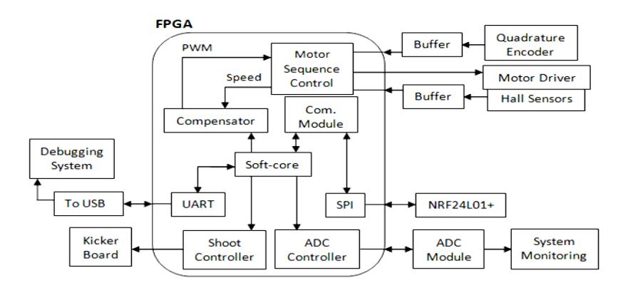
The processor is a Xilinx Spartan 3 (XC3S400) FPGA with a 65.520MHz oscillator for sequential processes and a soft-core CPU (TSK3000A) generated by Altium designer.
Communications System
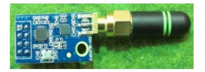
We have changed our communications system from XBEE to an NRF24L01+ based module. The reasons for this change to take place are as follows:
- Lower price
- Higher air data rate and faster communications
- Fast switching capability between the RX and the TX modes and the possibility of two-way communications using one module
- Automatic CRC checking, packet management and data retransmit capabilities
- More frequency range (More channels)
Currently our preferred settings and output results are:
- Channel 0x45 (frequency 2469 MHz)
- Packet size: 9Bytes Data, 5 Bytes address, 1 Bytes CRC
- Automatic retransmit: Max 15 times, 250us delay.
- Error Rate: 0%
- Data loss<1%
As communications with NRF24L01+ are based on SPI protocol, a microcontroller is used as intermediary between the central computer and the NRF Module, receiving commands through UART and sending them via SPI. To compensate for data loss, each packet is transmitted more than once.

Kicker Board
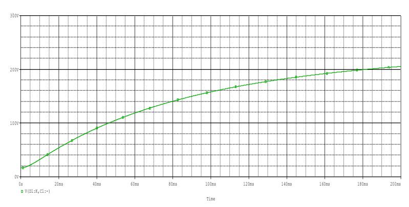
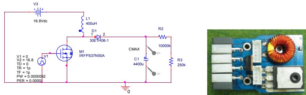
A few modifications were made to our last year's kicker board design in order to optimize it and ensure its reliability. The principles however, remain the same. The board, basically a DC to DC boost converter, charges a bank of two 2200uF capacitors up to 200 Volts and discharges them into the solenoids using two IGBTs.
Motor Driver
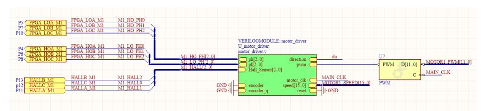
Each motor's BLDC driver unit consists of two modules; An FPGA based digital circuit as main controller and a power driver circuit. The controller receives Hall Effect sensors data, and then generates proper control signals for each motor.
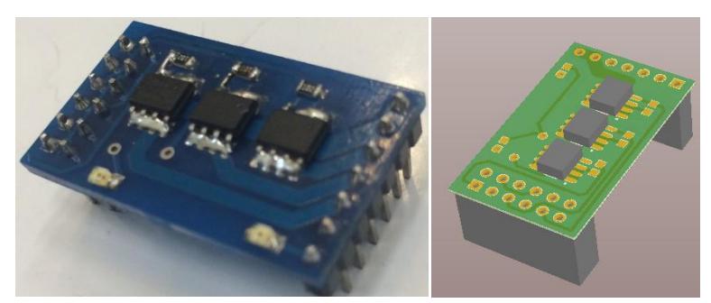
The power driver circuit is a three-phase inverter circuit using complementary N and P channel power MOSFETs in each phase. These MOSFETs are driven by TC4428 MOSFET drivers to minimize the switching loss. The three-phase inverter bridge receives signals from FPGA to provide commutation for each motor. These signals are ANDed with the PWM signal to adjust the average voltage applied to the motor winding.
Future Work
We plan to migrate to an ARM Cortex based CPU in order to increase our processor's reliability and solve the problem of implementing floating points in the FPGA. Other considered options are Xilinx Virtex family with internal hard-core Power-PC processors and Xilinx Spartan 6 series with internal DSP units for floating point calculations.
Our next generation robots will feature on-board positioning sensors to have an accurate estimate of their angle and speed, independent of the vision-system and its latency.
Control System
The result of the AI and high level control algorithms and decision makings are sent as three velocities from the Remote Host PC to each robot, namely $V^f$, $V^n$ and $\omega$, which are the forward, normal and the rotational speed of the robot respectively. The desired rotational speed of each motor is then calculated using a transformation, namely the Jacobian matrix.
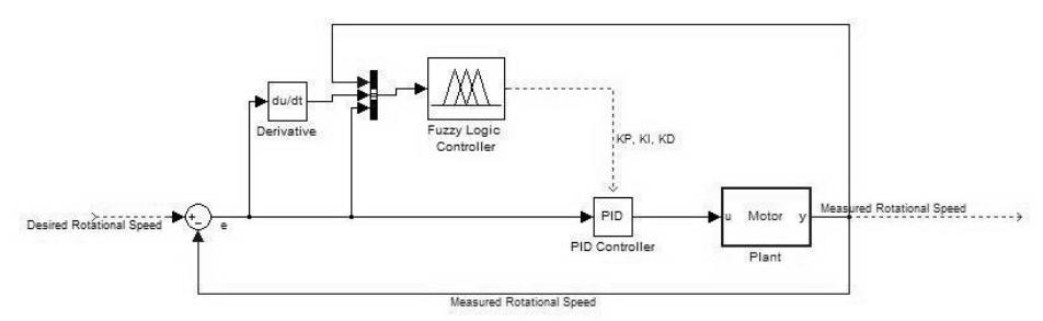
Now that the desired speed of each motor is specified, the speed control of each motor is considered. For this we have applied a Fuzzy-PID controller. In fact, the proportional, integral and derivate (KP, KI, KD) gains of the PID controller are adjusted according to FUZZY LOGIC. By applying this method one can benefit the precise characters of PID and the flexibility of fuzzy controllers. The major problem of applying the conventional PID to DC motors is the non-linear characteristics of the motor which are generally difficult to be modeled precisely. So, with tuned but static PID gains one cannot achieve the desired control specifications under different motor speeds and load disturbance. But by employing the selftuned Fuzzy-PID, dynamic PID gains are achieved, and one can get the desired control specifications under all the conditions.
The inputs of the Fuzzy-PID controller which the Fuzzification step is performed on them are the error of the speed (the difference between the current speed and the desired speed), the derivative of the speed error and the current speed of the motor. The reason for choosing these inputs is that the size of the error indicates how fast the controller should reduce the error, the derivative of the error is an indication of how the error is going to change, and the current speed is also chosen because the nonlinear characteristics of the motor is not the same at different speeds. Each input's universe of discourse is divided into five overlapping fuzzy sets {Negative Large, Negative Small, Zero, Positive Small, Positive Large} with triangular membership functions.
The motor and its driving system were connected to MATLAB software by serial communication. Experiments were conducted on the motors under different condition of errors, derivative of errors and instant motor speeds and at each condition, the parameters of the PID controller were tuned by the MATLAB with respect to the pre-defined rise time, settling time and overshoot. Then the results were used to make the rule table for fuzzy logic. Due to the importance of computational complexity on the FPGA the Takagi-Sugeno Deffuzification algorithm is employed. The self-tuning Fuzzy-PID controller has a relatively uniform and better performance in transient and steady state response, better dynamic response curve, small steady state error, small overshoot, shorter response time and high steady precision no matter how large the load disturbance is. The structure of the controller is shown in Fig.1.
Reasonably the robot has slip between the wheels and the ground in some amount. In absence of a sensor that measures the robot velocity, this slip cause an error between actual motion and the desired one. By means of an extended Kalman observer for state estimation which is implemented at the high level control loop, this error will be compensated. The performance of the compensation depends on how well the robots velocity is estimated by the extended Kalman filter.
software
architecture
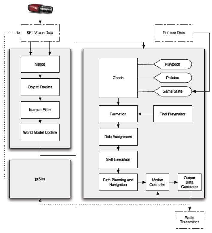
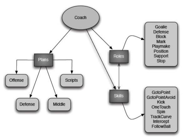
The Coach layer is the first step in the high level planning (decision making) loop. Choosing a formation for the team is done prior to any other decisions. According to policies, that are a mixture of manual configurations ( and game- state dependant updated values, each cycle the coach layer decides the team's formation. Therefore, each agent takes part in one of the main plans: defense, midfield and offense. Defense plan consists of agents which are near the friendly penalty area, including goalie and some blocker agents. Middle plan in which agents intend to possess the ball owned by opponent and diminish their attacking opportunities with marking, blocking, ball interception and etc. Offense plan includes the remaining agents that are going to create attacking chances to score. One agent always takes the role of the "playmaker" (the agent that possesses the ball), other offense agents should take suitable positions. After running the plans, a set of roles are assigned to agents in an optimized way, so that minimum movement is needed for agents to execute their roles. To perform a role, each agent may use a different set of basic skills. For example "marker" itself is a role but it uses the "gotopoint" skill to reach its target. The hierarchy of the coach structure is shown in figure 10.
As a matter of fact, in a small-size game, most of the time the game is in stop mode (i.e. ball is moved out and the game should be started either by a direct or an indirect kick). Thus, having a knowledgeable game play when the game starts (direct or indirect kicks) may result in more scores. Kickoff, indirect kick, direct kick and penalty kick are the main "non-play-on" plays in a small-size robotic game. To have more diverse "non-play-on" game plans, we have implemented a script language.
Dynamic Path Planner
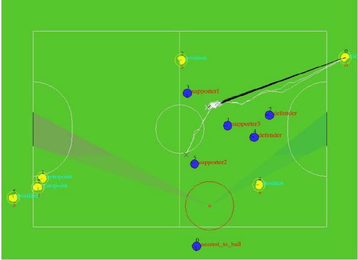
As it's been described in our previous robocup etdp [15], we create a Dynamic Environment Path Planning algorithm and since the RRT algorithm is the best choice for path planning in non-discrete environments [1][2], we decided to implement it based on RRT instead of dividing the playground to discrete grid , so we re-implement our ERRT path planner and add some new features to that, and it became a new path planner consisting these new features.
first of all we consider the field a little larger because of some circumstances in which path planning inside the field is impossible like when the ball is in corner area.
since the primary path retrieved from ERRT has fractures on account of its random nature, straightening the fracture containing path is done by the basis that says "go forward as much as possible". in order to lessen computation time algorithm starts to generating path on both robot-to-destination and destination-to-robot.
one thing that should be considered in using the obtained path is preventing robot from exiting path while it traverses its immediate turns. we handle this matter by limiting the maximum velocity of the robot by the angle of fracture and the distance to reach that.
Applying the proposed method in 2013 which resulted in achieving the first place of Robocup 2013 navigation technical challenge, confirms its efficiency and effectiveness.
Offensive Positioning
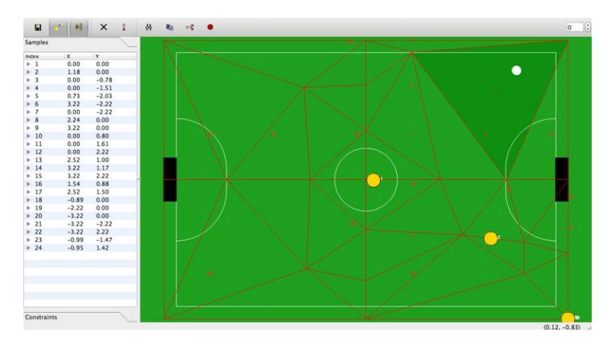
Positioning involves finding the best target position for agents who do not possess the ball regarding the field situation and team strategy [1]. In offensive positioning which is the case when one agent of us owns the ball, all the other agents should modify their position in field in order to increase the chance of receiving pass from the ball owner and increase the scoring chance. Therefore, considering the minimum effective movement in positioning is a crucial task. Here we focus our attention to a widely used algorithm of positioning in Robocup Soccer Simulation League, Delaunay Triangulation based positioning depending on the ball's position in the field, and we propose a modification to implement it in the offensive situation positioning of our small size soccer robots. In 2008 Hidehisa Akiyama and Itsuki Noda used Delaunay Triangulation of the field depending on the ball position to determine the agents' positions [2-4]. In this method a representative set of potential ball positions are the vertices of these triangles and in each potential ball position we can set the positions of all of our agents. During the match the positions of the agents are determined by an interpolation method between the vertices of the triangle in which the current position of the ball lies. This method has shown a great performance and was adopted by nearly all the teams participating in Soccer Simulation League of Robocup Competitions in recent years. One of the benefits of this method is its simplicity in implementation and initialization by the developer, since it can be done by a visual software namely fedit provided by Hidehisa Akiyama [5] and all the considerations of smooth movement of players between positions can be handled by the human intuition operation in a visual manner. In Fig.2 the Delaunay Triangulation of the field based on the representative set of ball positions in the GUI of fedit is shown. In each numbered potential position of the ball, the human developer determines the positions of all the agents. We modified some parameters in this software like the field dimensions and number of players to comply with SSL.
Defensive Marking Skill
Marking opponent's attackers is one of the most important defending skills and plays an important role in preventing the attackers from scoring. The most challenging part in this skill is determining which of our defenders should mark which attacker in order to get the best result without any conflict and have a man to man marking. In order to find the solution for assignment of opponent's attackers to our defenders, we were inspired by AUT2D 2012 2d soccer simulation team [9]. We found "Maximum Weighted Bipartite Matching" helpful for our assignment problem and employed it with Hungarian algorithm for solving the mentioned marking problem.
Maximum Weighted Bipartite Matching
Graph $G = (V, E)$ in which $V$ is the set of vertices and $E$ is the set of edges is called Bipartite if the set $V$ can be divided into two parts $A$ and $B$ such that,
$$A \cap B = \emptyset \quad (1)$$
$$A \cup B = V \quad (2)$$
, and also there does not exist any edge in $E$ that connects two vertices in the same set [6]. A subset $M$ of the set $E$ is a matching (collection of edges) when each vertex of $V$ is at most incident to one edge of $M$. Without loss of generality we can assume our graph complete by adding dummy vertices and edges of weight zero [6, 7].
If each edge of the graph is assigned a weight we have a weighted bipartite graph [8]. If the sum of the weights of the edges in a matching ($M_i$) is called the weight of that match $W(M_i)$,
$$W(M_i) = \sum_{e \in M_i} w(e) \quad (3)$$
, a maximum weighted matching $M$ is a match in such a way that every other matching has lower weight than the weight of $M$ [9]. In the proposed algorithm we employ Hungarian method to solve our assignment problem. This Maximum Weighted Bipartite Matching has been used in defensive skills in [8] and [9] as well.
Applying "MWBM" in our marking problem
At first we make our graph consisting of our defenders at one side and the attackers on the other side as the nodes. Be mentioned that we omit some of opponent's attackers by some initial checking. We don't use our blocker in our nodes either. Then we give a weight W(i,j) to each edge respecting some features. The weight in fact indicates the importance of marking the attacker j by our defender i. In fact if $F^k$ is the value of feature k and $R^k$ is the related coefficient and N is the number of the features, the weight of each edge is the sum of the features value multiplied by their related coefficients as shown in formula (4).
$$W_{(i,j)} = \sum_{k=1}^{N} R_k * F_k(i,j) \quad (4)$$
The coefficients are now set by hand, but we look forward to applying training procedures and high level algorithms for optimizing them.
Future Plans
The list of our current research is given bellow. The main attitude of the mentioned researches is concentrated on improving the artificial intelligent and control methods utilized in the software architecture.
- Applying machine learning methods for predicting the opponent's penalty kicker behavior.
- Re-implementing new Kalman Filter for reducing the vision system delay and getting more accurate objects speed and acceleration.
- Developing the robot's model with neural networks to improve the high level control and navigation technique and path planning algorithms.
References
[1] Hesam T. Dashti, Shahin Kamali and Nima Aghaeepour (2007). Positioning in Robots Soccer, Robotic Soccer, Pedro Lima (Ed.), ISBN: 978-3-902613-21-9, InTech, Available from: http://www.intechopen.com/books/robotic_soccer/positioning_in_robots_soccer [2] Akiyama, H., Noda, I.: Multi-agent positioning mechanism in the dynamic environment. In: RoboCup 2007: Robot Soccer World Cup XI. (2008) [3] H.Akiyama, I. Noda , H.Shimora, Helios 2008 Team Description Paper, RoboCup 2008. [4] H.Akiyama, Helios 2007 Team Description Paper, RoboCup 2007. [5] Part of Helios team released materials, available at: http://sourceforge.jp/projects/rctools/ [6] Lecture notes from Michael Goemans class on Combinatorial Optimization. http://math.mit.edu/~goemans/18433S09/matching-notes.pdf, 2009. [7] M. Paul. Algorithmen für das Maximum Weight Matching Problem in bipartiten Graphen. Master's thesis, Fachbereich Informatik, Universität des Saarlandes, Saarbrücken, 1989. [8] M.Norouzitallab, A.Javari, A.Noroozi, S.M.A. Salehizadeh, K.Meshgi, Nemesis Team Description Paper 2010,RoboCup 2010. [9] M.Malmir, M.Simchi, S.Boluki, AUT Team Description Paper 2012, Robocup 2012. [10] the industry standard for high performance graphics (2011), http:// www.opengl.org/, [accessed February, 2011] [11] Bruce, J., Veloso, M.: Safe multi robot navigation within dynamics constraints. Proceedings-IEEE 94(7), 1398 (2006) [12] S.Mehdi Mohaimanian Pour1, Vahid Mehrabi2, Alireza Saeidi3, Erfan Sheikhi4, Masoud Kazemi1, Ali Pahlavani4, Mohammad Behbooei5, and Parnian Ghanbari.: PARSIAN extended team description for robocup 2013