2014 Team Description Paper RFC Cambridge
Ciara Adkins, Eric Anschuetz, Kate Donahue, David Gaddy, Oozi Khan, Lisa Liu, Baker Logan, Evelyn Park, Aaron Ramirez, Ellen Robo, Elizabeth Schanne, Erik Schluntz, Morris Yau
Abstract This paper illustrates advances the RFC Cambridge team made in the 2013-2014 year, providing a guide for how our robots will change for the 2014 competition. This year saw a complete redesign on the computer science side, as we rewrote the code. On the mechanical engineering portion, we implemented internally geared drive trains, allowing us to have higher acceleration and experiment with dribblers.
Mechanical Engineering
[Content follows in subsections]
Internally-geared drivetrain
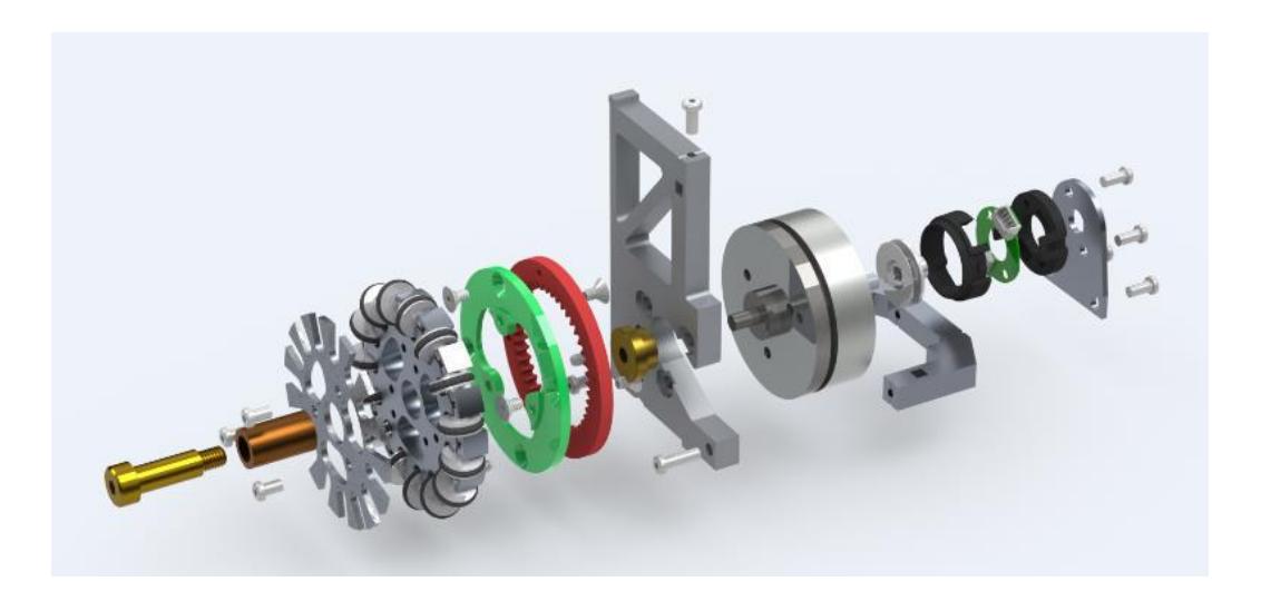
The majority of the mechanical work done this year focused on implementing the drivetrain design revisions outlined in our 2013 TDP: switching to an internally-geared design that would lower the center of mass of the robot and be more compact, making more space for other components. Though the design was mostly complete, with a physical prototype of a single drivetrain built last year, there were several manufacturing difficulties that prevented us from rolling out this change in time for the 2013 competition in Eindhoven.
In preparation for this year's competition, we have made a new robot with four new drivetrains and tested it. After refining the design in the coming weeks, we will scale up manufacturing to build enough new drivetrains for our entire fleet of robots. In preparation, we have been making enough parts for the new wheel design so they can be quickly assembled in April.
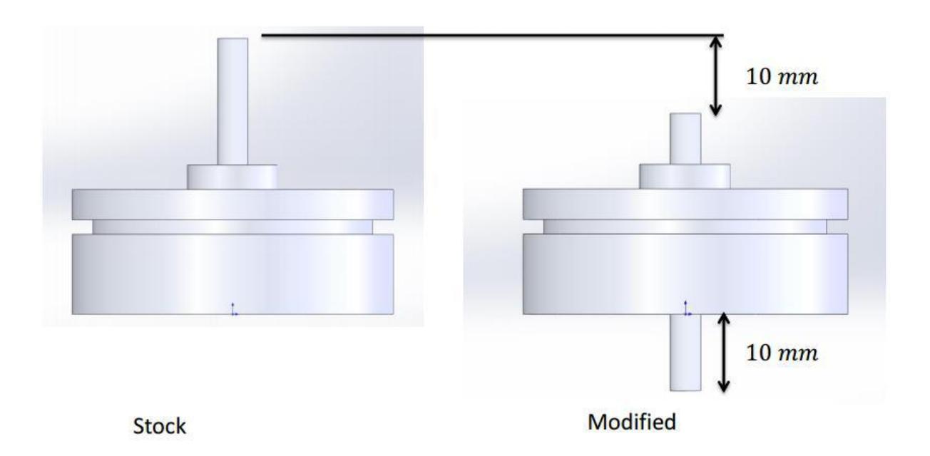
We have also started ordering custom-made motors from Maxon directly. While this doesn't involve large changes to the drivetrain design, it will save us in assembly time. Previously, we had to shorten the motor shaft to accommodate the more compact internal gear design. This was labor intensive and risky, as sometimes the process broke the motors. In addition, because there is no space to place the encoder assembly in front of the motor, we machined small posts to glue to the back face of the motor, on which we could place the encoder disk. However, making and gluing on these posts was very labor intensive, and it was difficult to ensure that the the posts were centered properly, leading to misalignment of the encoder assembly. This reduced quality of feedback, which in turn decreased the performance of our controls.
This year, we are ordering motors with the shafts already pushed through to the correct length. Though they are still being built and shipped to us, we predict this modification will also help us in reliability of control over the wheels.
Dribbler
This past fall, a major focus of the mechanical subteam was designing a dribbler. We built off knowledge from tests last spring to create a series of new designs using materials that avoided the bubbling and shearing problems brought up in last year's Team Description Paper. By switching from urethane rubber to a low-durometer (Shore OO-30) silicone rubber, we were able to get a much more durable roller with a better finish for contacting the ball.
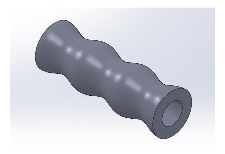
In addition to changing the material, we experimented with different geometrical parameters of the dribbler, particularly the shape of the dribbler. The above casting process enables us to work with shapes that are typically not machinable, and so we experimented with the following longitudinal shapes: flat, convex, concave, as well as a wavy shape based on a sine curve.
We found that the sine curve shape centered the ball the best and allowed for the greatest control of the ball while turning. Additionally, we experimented with the radius of the dribbler (i.e. how thick the thinnest portion was). We eventually settled on a medium thickness: too thin, and the dribbler was unable to retain the ball. Too thick, and the material would stretch outwards due to the centrifugal forces of the dribbler spinning, inadvertently pushing the ball away instead of catching it.
The dribbler design is dependent on creating a new generation of wheel modules. This is because moving the motors to the lower half of the robot frees up space for a wider dribbler above. Consequently, most of our efforts have been on making a robot with a completely redesigned set of internally geared motors. Now that we have accomplished that goal, a portion of our team will make the final modifications to incorporate it into the final design.
Thermoforming shields
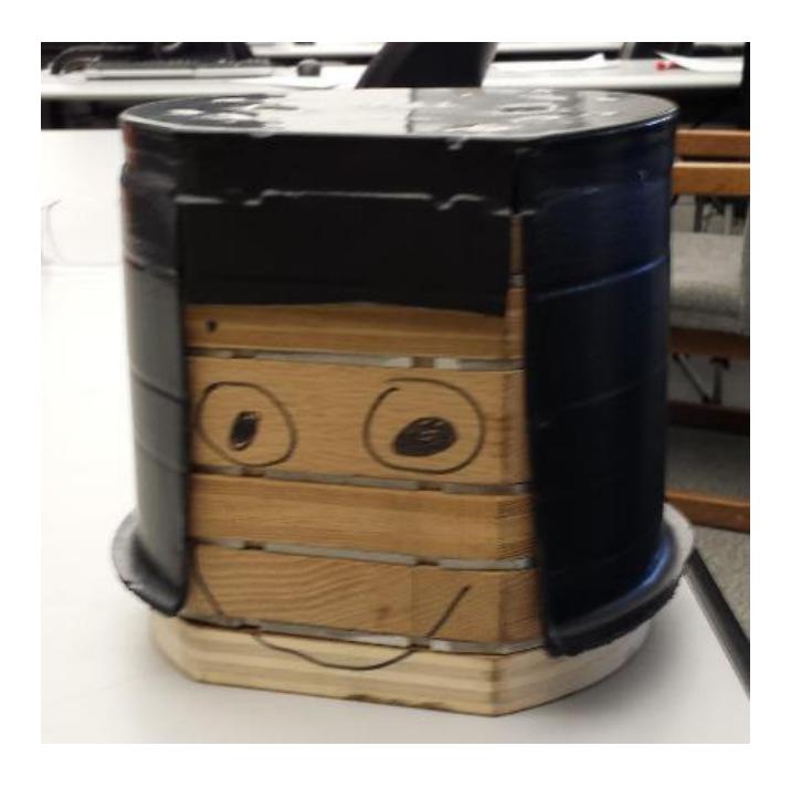
This year we are switching the method we use to manufacture our shields. In the past, the process involved manually heating and warping plastic sheets to achieve the general cylinder shape, then manually cutting out the holes for exposing the wheels and other parts of the robot. The resulting shields were not very robust and did not do a good job of protecting the robots. In addition, shields were highly inconsistent between individual robots, leading to alignment issues. In order to get a more uniform result, we investigated using vacuum thermoforming for creating our shields. A preliminary test with a cylindrical dummy mold showed that this would be feasible and that the thermoforming process was able to recreate the necessary level of detail for our purposes.
We are currently building a final mold out of specialized foam, which can be used several times to create a full set of new shields.
New Top Plate
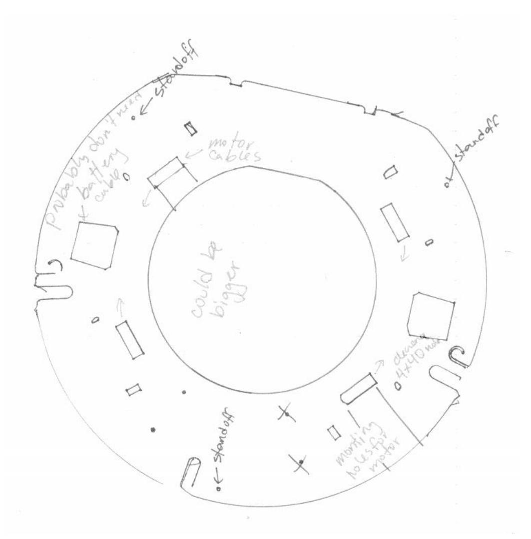
A major issue for the team as a whole is malfunctioning motors. During the 2013 competition in Eindhoven, we started out with a full fleet of robots but by the end had only enough motors for two robots. This is a particularly bad since the motors are the costliest components of the robot. Though the majority of failure cases involve the electrical components of the robot, e.g. poor current protection, we recently noticed that several motors malfunctioned due to the ribbon cable being worn or torn enough to sever one of the leads coming of of the motor. We determined that this was caused by the way the ribbon cable needs to be twisted in order to be plugged correctly into the motherboard, which led to the cable rubbing against the sharp edges of the top plate and eventually being cut.
More generally speaking, the overall cable management on the robot needed improvement. In addition to broken motors, wiring for other components such as encoders and batteries would break from getting caught on edges/corners of the top plate, or from the repeated bending they underwent. The convoluted cable wiring also greatly slowed down how fast we could repair the robot or replace components during an actual match. To address this problem, this year we are working on drilling out additional holes and reconfiguring the top plate to provide freer movement of cables (less twisting) and better storage (less snagging while moving other parts of the robot).
Next year, our plan is to change the design of the motherboard so that the connections will be better positioned to completely avoid this issue. However, for the time being we are focusing on mitigating the worst parts of the twisting in order to preserve the motors.
Computer Science
Over the past year, we have changed the way our code is structured. We changed the way different systems, such as strategy, path planning, robot communication, and others are linked to a messaging system. Each module sends different message types that report updated state or new computational results. Other modules can register as listeners for different message types and receive event handlers when changes occur. There are several advantages to this system. First, It is easy to exchange modules with alternative approaches for doing the same computation. Since each module is linked to others only by the messages it sends and registers for, it is simply a matter of starting one module instead of the other and does not require any changes in the other modules. Another advantage is that new information can be processed as soon as it is received. Previously, new information had to make its way through several control loops that ran at set frequencies. With the new event based messaging system, new data is processed as soon as an event is triggered.
This year we focused on changing our codebase to a Messaging Architecture to make it more robust, more modular, and more scalable for future development. Previously, there was no separation between modules, and calls were made between many different places in the codebase, making debugging and isolating problems very difficult. To replace this, we created a central Messaging System, which each part of the code interfaces with, instead of interfacing directly with other classes.
For instance, instead of our strategy algorithm waiting in a loop for each new piece of information about the field state, it passes a handler to the Messaging System so that it can be notified immediately when there is more information. The Messaging System is also designed for high concurrency, with each category of message running on its own thread so that a bottleneck in one part of the code will not affect the performance of another.
Having a decoupled messaging architecture also opens up the possibility for us to separate different pieces of the code into different executables potentially even running on different computers over a network interface.
Electrical Engineering
This year, the electrical engineering team focused on debugging old problems that showed up in the 2013 competition. Because this year saw such dramatic changes in the computer science and mechanical engineering groups, we are planning to postpone the next generation in electrical engineering design until next fall, for financial reasons as well as constraints on the time of team members.