RoboDragons 2014 Extended Team Description
Yuji Nunome, Tomonori Hibino, Akifumi Hosino, Shohei Yokota, Yusuke Adachi, Masahide Ito, Kunikazu Kobayashi, Kazuhito Murakami, Tadashi Naruse
Aichi Prefectural University
Abstract This paper describes a system configuration of RoboDragons, a team of Aichi Prefectural University, Japan. The robots were newly developed last year. The features of the robot are to use a 50 watt DC blushless motor for driving an omni-wheel, an improved chip-kicker, a simple proximity sensor, and a wireless LAN for communication. Software on the RoboDragons' system is almost the same as the one used last year. However, we improved the estimation method of moving-time of the robot. We describe it in this paper. These are also shown in the Robo-Dragons' TDP. In this paper, in addition to these topics, we describe an algorithm to realize the continuous passes forming the pentagram. The video is available. You can watch it on our site, http://www.ist.aichipu.ac.jp/lab/narulab/index e.html.
1 Introduction
In the extended team description paper (ETDP) of RoboDragons 2014, we summarize the hardware and the software architecture of our system and then describe in detail the improvement of the software done this year.
For the hardware, we developed a new robot last year. Features of the new robot are dimension with 125 mm height and 178 mm diameter cylinder, a 50 watts DC brushless motor for driving an omni-wheel, an improved chipkicker, a simple proximity sensor, and a wireless LAN for communication. The detail is written in RoboDragons 2013 TDP [1].
Software development is crucial for the performance of the robot system. Though we use almost the same software as the 2012 system which we described in RoboDragons 2012 TDP [2], we improved the method of estimating the arrival time of the robot to the given destination. This paper shows it in detail. Moreover we describe an algorithm to realize the continuous passes forming the pentagram. The video is available. You can watch it on our site, http://www.ist.aichi-pu.ac.jp/lab/narulab/index e.html.
2 Robot Hardware
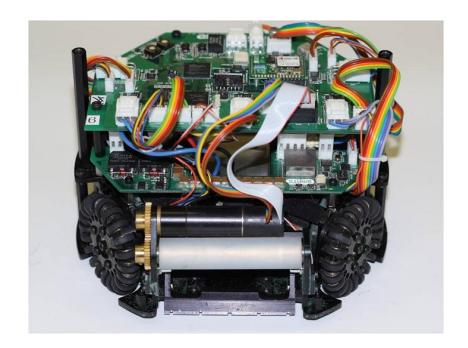
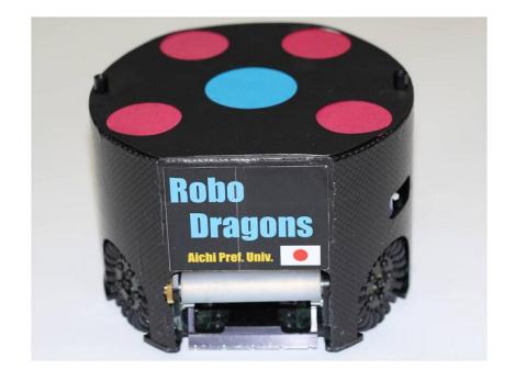
In this section, we briefly describe our current robot. We show that the robot with/without cover in Figure 1. The features of our robot are shown as follows.
- Cylinder with dimensions of 125 mm height and 178 mm diameter.
- Weight : 2.3 kg.
- Maximum percentage of the ball coverage : about 18%.
- Motor : 50 watt DC brushless motor for driving a wheel.
- Simple proximity sensor.
- Wireless LAN for communication.
2.1 Components of the robot
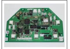
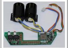
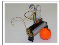
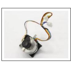
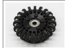
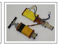
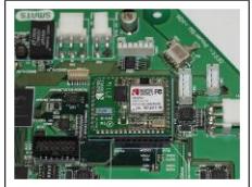
All devices attached to the robot are shown in Fig. 2. The description of each device are presented in Table 1. The details are written in RoboDragons 2013 TDP [1].
Summary of the robot
| Device | Description |
|---|---|
| Control Unit | CPU: SH2A processor (Renesas Electronics Corporation) operated with 196 MHz clock. Peripheral circuits (except analog circuits) are almost in the Xilinx's Sparta-6 FPGA. Boost Converter Convert from 18.5 V DC to 150 V - 200 V DC. Condenser has a capacity of 4400 µF. Charging time is about 2 s (when output voltage is 200 V). |
| Motor | Maxon "EC 45 flat 50W". Gear reduction ratio between motor and omni-wheel is 21:64. |
| Wheel | 4 omni-wheels, each has 20 small tires in circumference. Diameter: omni-wheel 55 mm, small tire 12.4 mm. |
| Dribble Device | Dribble roller: 16 mm in diameter and 73 mm in length, made of aluminum shaft with silicon rubber. Motor is Maxon "EC 16 30W". |
| Ball Sensor | Infra-red light emission diode and photo diode pair. |
| Kicker | Kick bar is made of 7075 aluminum alloy. Solenoid is a coil winding 0.6 mmϕ enameled wire. Straight kicker kicks a ball with over 10 m/s velocity at maximum. Chip-kicker kicks a ball as far as 4 m distance at maximum. Communication IEEE 802.11g wireless LAN. |

2.2 Robot control program
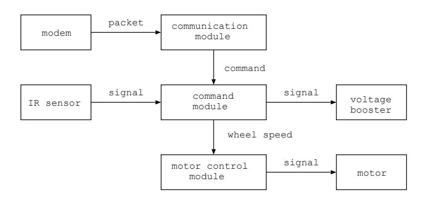
The block diagram of the robot control program is shown in Figure 3. In the figure, each box named module is a thread program which run independently and other boxes are hardware which are controlled by modules. Basic control method is the same as the robot developed in 2010 [6].
2.3 Configuration of communication packet
Thanks to the fast communication ability of the radio system, we redefined the communication packet configuration. The packet consists of 20 byte header, 49 byte packet body and 2 byte footer. The packet body consists of 8 byte command for each robot and 1 byte common command for all robots.
The 8 byte command is shown in Table 2. Basic idea of the command is that we give the moving vector and the angular velocity of the robot. In the 6th and 7th bytes, we give the kick command. "gggg" field selects kicker (straight/chip) and kicking mean (normal/forced). The normal means to kick when the ball sensor detects the ball while the forced means to kick just after the command is issued.
The 1 byte command for all robots is mainly used for debug purpose.
Command for each robot
| Byte | Config. | Description |
|---|---|---|
| 1st byte | aaaabbbb aaaa: Robot ID, bbbb: Robot velocity | |
| 2nd byte | bbbbbbbb bbbbbbbb | Robot velocity, 0 - 4095 (mm/s) |
| 3rd byte | cccccccc cccccccc | Moving direction, Resolution is 2π/512 radian |
| 4th byte | 000cdeee | c: Moving direction, d: Rotation direction, 0:cw, 1:ccw eee: Angular velocity |
| 5th byte | eeeeeeee eeeeeeee | Angular velocity, 0 - 2047 (deg/s) |
| 6th byte | ffffffff ffffffff | Kick force, 256 levels |
| 7th byte | gggghhhh | gggg: Normal/Forced kick, hhhh: Dribble velocity, 8 levels for each rotation direction (cw, ccw) |
| 8th byte | iiiiiiii iiiiiiii | CRC code |
3 Software System
3.1 Overview of the software system
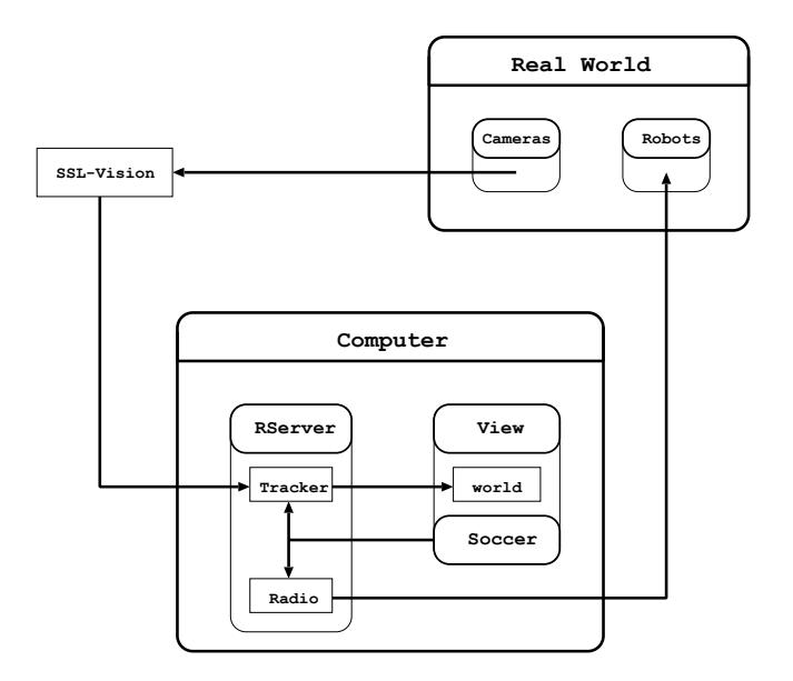
In this section, we show how our software system in host computer is composed and relates to the information from real world. The overview of our software system is shown in Figure 4.
The host computer is a commercial one. CPU is Intel Core i7 4700MQ and main memory is 4 GB. OS is Ubuntu 13.10/Linux. Three main modules are running, each of which is composed as follows.
(1) The Rserver module receives SSL-Vision data and uses tracker submodule to predict the ball and robots positions by using Kalman Filter. They are stored in memory as world date, which are shared by viewed Soccer module. To send a command to each robot, a radio submodule is used.
(2) The View module is used to see the simulated image of real world so that they are easy to understand the situation. To do so, users set the number of robots and team color.
(3) The Soccer module makes an action command for each robot. By using the world data, the module chooses the best strategy, gives a role to each robot, and calculates a moving path for each robot.
3.2 Improvement of arrival time estimation
After the path planning for given destination, the estimation of moving-time to destination is necessary in many cases. Examples are the case finding the fastest robot to get to the destination, the case preventing an opponent robot from getting the ball, and so on.
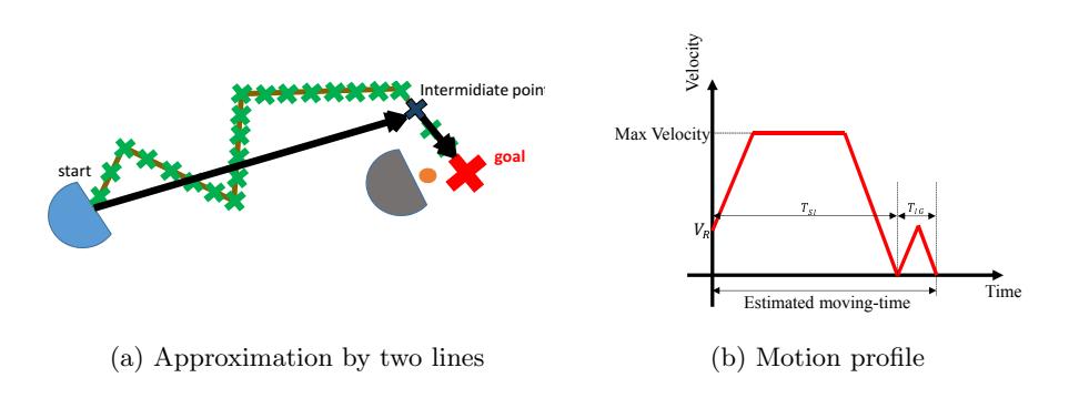
We use the RRT algorithm [7] for path generation. However, in our system, the estimation of moving-time is quite simple, i.e. estimating it as the moving-time on the straight line connecting the current position and the destination under the predefined motion profile as shown in Figure 5.
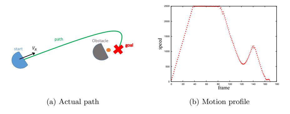
In case that obstacles are in the field, as shown in Fig. 6, the path is not straight line. An actual path and a motion profile will be given by Figs. 6(a) and 6(b), respectively. Above approximation results in big error.
To reduce estimation error with keeping the real time computation, we adopted intermediate points method. The number of intermediate points being used depends on the situation. We use one intermediate point here. An example is shown in Figure 7. In the figure, a green line is a path generated by RRT. The intermediate point is given by the farthest point on the RRT line that the robot can move straight without colliding the obstacle. The estimated moving-time is given by the moving-time on the two straight black lines (current position - intermediate point and intermediate point - goal) under the motion profile shown in Fig. 7(b). We assume the velocity reduces to zero at the intermediate point.
With this estimation, we can reduce the approximation error by 51%.

4 Star Passing
Our team have been improving the precision of passing for a decade and developing the offense strategies extensively using the precise passing. With this, we could keep advantage of a game and make goals in the games played in the RoboCup Japan open and the RoboCup world competition. As a result, we could achieved a good ranking in the past competitions. On the other hand, we have many chances to demonstrate our system in robot events held mainly in Japan. In the events, attractive demonstrations are necessary. One of them is a star passing which is a continuous passing play forming the pentagram. In this section, we describe it in detail.
4.1 Pentagram Passing Demonstration
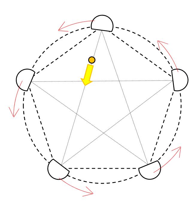
The demonstration is like the followings: 1) put each robot on the vertex of a regular pentagon, 2) a robot with the ball passes it to the robot which is located on the vertex of the pentagram, 3) each robot goes round on the circle the vertices of the pentagon make, 4) continue the passing. (See figure 8.)
4.2 Basic Technology
To realize the pentagram passing, we need following techniques,
- The passing robot should approach the ball by turning its face toward the receiving robot,
- Precise facing angle should be computed.
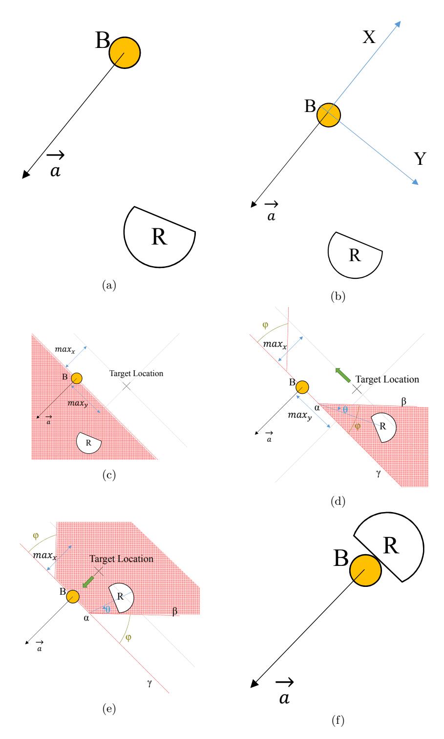
In the following, we describe the first technique. Look at the figure 9(a). In the figure, R is a robot, B is a ball and $\overrightarrow{a}$ is a vector showing the pass direction. Our purpose here is to control a robot beginning from Fig. 9(a) and ending in Fig. 9(f), changing its face direction (straight line part of the robot) toward the direction of $\overrightarrow{a}$ as shown in each subfigure of Fig. 9. Let us explain it in detail. First, we take an X-Y coordinate as shown in Fig. 9(b) and define the following variables and constants.
- $(x_R, y_R)$ : robot position
- $(x_t, y_t)$ : target location
- BallRadius : ball radius
- RobotRadius: radius of the circle encompassing robot
- DribbleWidth: length of dribble roller
- $max_x$, $max_y$: $BallRadius + C_1$, $BallRadius + RobotRadius + C_2$, respectively, (where $C_*$ is a given constant (i.e. tuning parameter))
In case that the x-coordinate of the robot is negative $x_R < 0$ as shown in Fig. 9(c), we give the target location $(x_t, y_t)$ as follows,
$$x_t = max_x \tag{1}$$
$$y_t = \operatorname{sgn}(y_R) \cdot max_y, \tag{2}$$
where $\operatorname{sgn}(\cdot)$ is a sign of $\cdot$. The target location is a position that the robot can approach the ball without touching it. During the approach, the robot changes its face direction toward the direction of vector $\overrightarrow{d}$.
In case that the robot is in the pink area shown in Fig. 9(d), we give the target location $(x_t, y_t)$ as follows,
$$x_t = max_x \tag{3}$$
$$y_t = \operatorname{sgn}(y_R) \cdot \max_y \cdot \frac{\theta}{\phi},\tag{4}$$
where the point $\alpha$ is $(0, C_3)$ and $C_3$ is a given constant, the angle $\phi$ is 30 degree in our system and $\theta$ is the angle $\angle \beta \alpha R$. Note that the robot moves on the line connecting the robot and the target location, though the target location varies from time to time according to the value of $\theta$. We compute it in the same way when the robot is in the position symmetrical to the x-axis.
In case that the robot is in the pink area shown in Fig. 9(e), we give the target location $(x_t, y_t)$ as follows,
$$x_t = \frac{2 \cdot BallRadius - max_x}{\frac{\pi}{2} - \phi} \theta + max_x \tag{5}$$
$$y_t = 0. \tag{6}$$
As the robot moves toward the x-axis, the target location goes closer to the ball, just in front of the ball (when $C_3$ is adequately chosen). Then, the robot goes forward and the kicker kicks the ball under the control of the proximity sensor.
5 Conclusion
This paper described the summary of the robot and software system of Robo-Dragons 2014 and described an improved method of estimating the moving-time of the robot when a path is given. Moreover, this paper described the star passing demonstration program.
References
- Kotaro Yasui, Yuji Nunome, Shinya Matsuoka, Yusuke Adachi, Kengo Atomi, Masahide Ito, Kunikazu Kobayashi, Kazuhito Murakami and Tadashi Naruse "RoboDragons 2013 Team Description", RoboCup 2013 symposium CDROM, 2013
- Kotaro Yasui, Taro Inagaki, Hajime Sawaguchi, Yuji Nunome, Hiroaki Sasai, Yuki Tsunoda, Shinya Matsuoka, Naoto Kawajiri, Togo Sato, Kazuhito Murakami and Tadashi Naruse "RoboDragons 2012 Team Description", RoboCup 2012 symposium CDROM, 2012
- Kotaro Yasui, Taro Inagaki, Hajime Sawaguchi, Yuji Nunome, Hiroaki Sasai, Yuki Tsunoda, Shinya Matsuoka, Naoto Kawajiri, Togo Sato, Kazuhito Murakami and Tadashi Naruse "RoboDragons 2012 Extended Team Description", RoboCup 2012 symposium CDROM, 2012
- http://www.toppers.jp/en/index.html
- http://en.wikipedia.org/wiki/TRON project and http://en.wikipedia.org/wiki/ITRON
- Akeru Ishikawa, Takashi Sakai, Jousuke Nagai, Taro Inagaki, Hajime Sawaguchi, Yuji Nunome, Kazuhito Murakami and Tadashi Naruse "RoboDragons 2010 Team Description", RoboCup 2010 symposium CDROM, 2010
- James Bruce, Manuela Veloso, "Real-Time Randomized Path Planning for Robot Navigation", Intelligent Robots and Systems, 2002. IEEE/RSJ International Conference on Volume:3, pp.2383 - 2388, 2002