RoboFEI 2014 Team Description Paper
Fernando Rodrigues Jr., Danilo Pucci, Feliphe G. Galiza, Caio Schunk, Vitor Hugo M. Beck, Francisco Biaso, Victor Torres, Thiago Silva, Victor Amaral, José Angelo Gurzoni Jr., Reinaldo A. C. Bianchi, Flavio Tonidandel
Robotics and Artificial Intelligence Laboratory Centro Universitário da FEI, São Bernardo do Campo, Brazil
http://code.google.com/p/gerrit/ · http://dlib.net/ · http://eigen.tuxfamily.org · http://code.google.com/p/ceres-solver
Abstract This paper presents an overview of the RoboFEI team state for the RoboCup Small Size League competition. The paper contains descriptions of the mechanical, electrical and software modules, designed to enable the robots to achieve playing soccer capabilities in the dynamic environment of the Small Size League.
1 Introduction
For the RoboCup 2014, RoboFEI team intends to use basically the same electronic project that has been used during the last four years, with minor modifications. The Mechanical design is under maintenance, studies are focused to avoid the chip kick parts deformations.
The strategy software has been refactored and turned the code more agile, easy and efficient. The next step is add new features and functionalities to improve the robot's skills.
2 Electronic Design
The electronic design has been used for the last four years and received few modifications since reached desired performance and stage of development.
RoboFEI's electronic consists of two boards: the main board is responsible for all embedded computation and robot's motion control. The Kicker board commands the kicking devices and it's associated power electronics. These two boards are described in details in this section.
2.1 Main Board
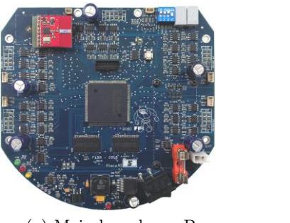
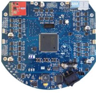
The main board (Fig. 1) has a Xilinx Spartan 3 FPGA (XC3S400) responsible for performing all the logic and control functions. Embedded into this FPGA are a soft-core microcontroller IP, the Microblaze running on version 8.1, five brushless motor controllers, sensor control modules and the kicker board command. The integration of all the functions, including the microcontroller, in the same IC eliminates the difficulties related to component interconnection and avoids the maintenance of multiple firmwares, while at same time considerably reducing the number of components on the board. The Xilinx Spartan 3, with its Microblaze soft-core operating at 50 MHz, provides fast computation, because of its integrated hardware FPU (floating-point arithmetic unit). The embedded firmware is loaded in a 4M words PROM memory connected to the FPGA.
The five brushless motor drivers are designed with the IRF7389 N-P complementary channel MOSFETs, an feature Allegro ACS712 current sensors. The reading of the ACS712 is made by a AD7928 Analog-to-Digital IC. The power to the main board and motors is provided by one LiPo battery of 3-cells (11.1V) and 2200 mAh capacity.
The radio system is based on the Nordic nRF24L01+ transceiver. These transceivers operate on the frequency range between 2.4 and 2.5GHz and have data transmission rates of up to 2M bps, allowing telemetry data to be obtained from the robots live during the matches. Each robot carries one transceiver, connected to the microcontroller via SPI bus, which is used to both send and receive data. The robot's transceivers communicates with the radio station connected to the strategy computer. This radio station contains two nRF24L01+ modules, operating on independent channels, one to receive and another to transmit data. An ARM7 CPU is responsible for the transceivers operation, data queuing, data integrity validation and interfacing with the USB port of the radio. The board also features a RF amplifier based on the MGA-85563 IC, used to boost the TX signal to 15dBm, ensuring enough power to reach the robots reliably even at larger distances.
Although RoboFEI's Main board is a fully functional and mature hardware design, its life-cycle is still closely monitored. A new revision of the board, shown in Fig. 1(b), has been developed. The RAM memory was not being actively used and has been replaced by a SPI flash memory, intended to store the robot's sensors and status measurement data. A motor-enable circuit with an IRF9310 MOSFET was also added, to protect the transistors on the brushless controller circuit from transient surges during power on and off. The last addition was an auto power-off circuit, to avoid damage to both the battery and electronics circuitry in case the robot's battery gets exhausted (i.e. if it is forgotten powered on).
2.2 Kicker Board
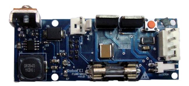
The kicker board, shown in Fig. 2.2, is responsible for controlling both the shooting and chip kick devices. It uses a boost circuit designed with the MC34063 IC. This IC produces a 100 KHz PWM signal that charges two 2700 µF capacitors up to 200V. The MC34063 controls the whole circuit, sparing the main-board's CPU from the need to generate the PWM signal and monitor the capacitor's charge. The board features two IRFSL4127 MOSFETs, responsible for activating the shooting and chip solenoids. Its power supply is independent, fed by a 3-cell (11.1V), 800mAh, LiPo battery, and all the connections to the main board are opto-coupled, to avoid spikes and eventual damage to sensitive electronic circuitry.
3 Mechanical Design
In compliance with the SSL rules, the height of the robot is 148 mm, the maximum percentage of ball coverage is 15% and the maximum projection of the robot on the ground is 146 mm.
The current robot uses a 6000 series aluminum alloy as main material, the factor hardness/weight has a good relation and less frequent part replacements are needed. Wheel axes and the small rollers of the omni-directional wheels are exposed to severe stress thus are made of stainless steel instead. Nylon is found in battery's supports due to electrical isolation and its lightweight.
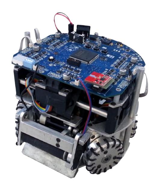
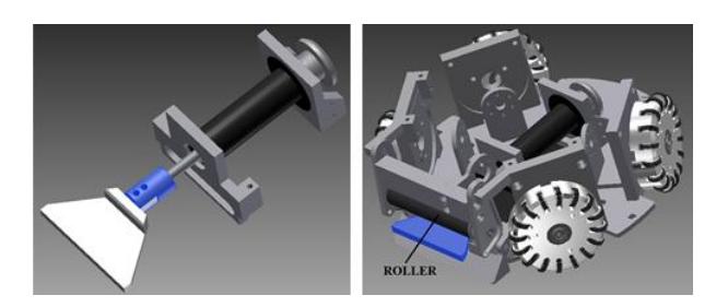
The Robot weighs about 2.6Kg and the general design could be seen on Fig 3 and 4.
Table 1. Robot's Mechanical Specifications.
| Height | 148 mm |
|---|---|
| Weight | 2,6 kg |
| Percentage of ball coverage | 15% |
| Main Material | 6000 series Aluminium Alloy |
| Roller bar material | Polyurethane (PU): Hardness of 20, 25 and 30 Shore A |
| Driving motor | Maxon EC-flat 45 50W |
| Gear ratio | 3:1 |
| Dribbler device motor | Maxon EC-Max 22 25W |
| Solenoid Plunger material | SAE1020 steel |
| Solenoid coil | AWG21 wire |
4 Path Planning and Obstacle avoidance
The path planning and obstacle avoidance algorithm employed is based on the Rapid-Exploring Random Tree (RRT) with KD-Tree data structures, proposed by [1], and on the ERRT algorithm developed by [5], complemented by an algorithm to include preferred path heuristics and set the angle of approach. The algorithm based on RRT was chosen because (i) its capacity to efficiently explore large state spaces using randomization, (ii) the probabilistic completeness offered, (iii) its lookahead feature and (iv) the easiness of the algorithm's extension, when new constraints or heuristics are deemed necessary.
This section focuses on describing this add-on algorithm, which is implemented on top of the ERRT base algorithm.
The add-on algorithm has the function to set the angle which the robot approaches the ending point, as commanded by the strategy layer, an item that many path planners do not treat. It is not desirable, for example, that a robot going to the ball on the defensive field accidentally hits the ball in the direction of its own goal, or yet, that an attacking robot arrives at the ball in a position in between the ball and the opponent's goal. To create a path that conforms to the angle of approach requirement, a circular virtual obstacle centered on the ending point is created, with a 10° width circle segment and vertex at the desired angle removed. This effectively forces the path planner to create a path the reaches the ending point passing through this 10° opening. The radius of this obstacle-like constraint is set to a value close to half the size of a robot.
5 Strategy System
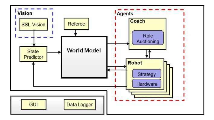
For this year we will use the same software structure (Fig. 5) used last year that basically consist of some world modeling blocks, logically independent agent modules, and visualization and data logging blocks. For this season the work is concentrated at a refactoring process that the software is undergoing.
5.1 World Modeling
The world model is updated by the state predictor module. This module receives vision data from the SSL-Vision and motion command data from the agent modules, sent when they command the robots via radio, and performs state predictions. The prediction is to advance the positions sent by the SSL-Vision from their original capture time to the present and then forwarding one strategy cycle in the future, the so called latency of the strategy system. This latency is currently on the order of 80ms.
The prediction algorithms used for ball, robots and adversaries are different. The ball prediction is made by an Extended Kalman filter (EKF) (see [7]), a well known method for position estimation.
The robot's prediction is performed similarly to [2], with multi-layer perceptron neural networks. These networks are trained off-line to learn the robot's motion model, receiving past frames and motion commands as input and a frame n steps in the future as output. Once trained, the networks are used for on-line estimation of the robot's position and rotation.
As for opponent estimation, currently it is done with simple extrapolation of the last velocity data and Gaussian functions.
5.2 Agent Modules
Each robot player is an independent module, executing its own instance of one or more strategy submodules and its hardware specific functions (such as motion control and sensing). The current implementation relies basically on a layered strategy architecture and a market based approach for dynamic allocation of functions, both described ahead on this section.
5.3 Strategy module
Building multi-agent systems in a layered architecture with different levels of abstraction is a popular approach (see [6], [3] and [4]) well suited as foundation for machine learning algorithms, one of the research goals. For this reason, the strategy module architecture was divided in three abstraction layers.
The lowest layer has the so called Primitives. Primitives are actions that mostly involve directly activating or deactivating a hardware module such as to kick the ball with a given strength, activate the dribbling device, rotate or move to a position.1
1 Actually, moving to a position is a special case of a primitive with underlying complex logic. It calls the path planning system to perform obstacle avoidance.
On top of the primitive layer, is the Skills layer. Skills are also short duration actions but involving use of one or more primitives and additional computation, such as speed estimation, forecasting of objects' positions and measurement of primitive tasks' completion. This layer has a small set of skill functions, yet that represent the basic skills required in a robot soccer game, like shooting the ball to the goal (aiming where to shoot), passing the ball to a teammate, dribbling, defending the goal line or tackling the ball (moving toward the ball and kicking it away).
One example of such skill is the Indirect Free Kick skill, which employs a multi-criteria weighted evaluation to determine the best for the robot to pass the ball to. Grids are constructed in different areas of the field, then the weighted multi-criteria evaluation function is employed to decide which of the grids contains the best candidate position. Once the area is chosen, the function recomputes using a finer grid, to determine the exact position. The objectives evaluated are the Euclidean distance of each position, in relation to both the robot and the ball, the width of the angle a robot in that position would have to to kick to the goal and the distance between the current positions of the teammates receiving the pass and the chosen positions in the grid.
The skills are employed by the Roles layer, which contains different roles, created using combinations of skills and the logic required to coordinate their execution. There are roles called fullback, defender, midfielder, striker, forward and attacker. No particular robot is tied to a given role (except the goalkeeper), and there is no limitation on how many instances of the same role can exist, what allows dynamic selection mechanisms to create role combinations without restrictions.
5.4 Work In Progress
The robot's mechanical is under continuous improvement, the height of chip kick device and the roller ball handling are requiring main attention. The Chip kick system is under strong mechanical stress. After some kicks the parts needs to be replaced, the exceeded dissipation of energy and non-optimized geometry causes important deformations, thus we have been working in a new mechanism with the proposal to increase the lever arm distance to preserve the same torque with less force values.
Our solenoid must be optimized, it's super dimensioned occupying too much space and wasting plenty amount of energy. The power dissipation is damaging some mechanical structures leading to frequently repairs. The optimization will be based on studies about electromagnetic theory using finite elements method (FEM) looking for an optimal design. Parameters like plunger and outer coil diameter, plunger material, voltage and time charge of capacitors will be considered.
Aiming at improving the quality of the ball handling, a new roller mechanism is being developed, the device consists of a inverted pendulum where the damping is provided by a viscoelastic foam.
After almost a year into the refactoring code project, it was very positive. The implemented software is consistent with its conceptual design and the code review based on code standards helps keeping the code clean and easy to maintain.
About an year ago, we started a code refactoring project, with a new major software version. The results are very positive. With the refactoring, the programming code is once again consistent with its conceptual design, what removed several glitches and deadlocks, and also allowed us to view and fix parts of the program that indeed had conceptual errors. One of the basis of the new code is a continuous code review system, by which at least one reviewer (among the programmers of the team) must sign-off the code before it is released, avoiding problems in code readability, such as lack of clarity and comments, as well as standardization and performance problems. The review system has proven so positive that we intend to try tool for Git repositories called Gerrit2, that controls the work-flow of peer code reviews and controls them before the actual commits to the main repository.
2 http://code.google.com/p/gerrit/
As the refactoring project comes close to completion, we resumed the work on new code, adding new features and functionalities. One of these new functionalities is the research of an optimized scientific library to provide linear algebra support, with matrices operations, numerical solvers and optimization algorithms. This is still early work, but so far the candidate libraries are Dlib3, Eigen4 and Ceres5.
5 http://code.google.com/p/ceres-solver
Acknowledgments
We would like to thank, in advance, the Small Size League Committee, for the consideration of our material. We would like also to immensely thank the staff of Centro Universitário da FEI, for all the help we always received.
References
- A. Atramentov and S. M. LaValle. Efficient nearest neighbor searching for motion planning. In IEEE International Conference on Robotics and Automation, pages 632–637, 2002.
- Sven Behnke, Anna Egorova, Alexander Gloye, Raul Rojas, and Mark Simon. Predicting away robot control latency. In Proceedings of 7th RoboCup International Symposium. Springer, 2003.
- Michael Bowling, Brett Browning, and Manuela Veloso. Plays as effective multiagent plans enabling opponent-adaptive play selection. In Proceedings of International Conference on Automated Planning and Scheduling (ICAPS'04), 2004.
- Brett Browning, James Bruce, Michael Bowling, and Manuela Veloso. Stp: Skills, tactics and plays for multi-robot control in adversarial environments. In IEEE Journal of Control and Systems Engineering, volume 219, pages 33–52, 2005.
- James Bruce and Manuela Veloso. Real-time randomized path planning for robot navigation. In Proceedings of IROS-2002, 2002.
- Maja J Mataric. Learning in behavior-based multi-robot systems: Policies, models, and other agents. Cognitive Systems Research, pages 81–93, April 2001.
- G. Welch and G. Bishop. An introduction to the kalman filter. Technical Report TR 95-041, Department of Computer Science, University of North Carolina, 2001.