RoboJackets 2014 Team Description Paper
Justin Buchanan, Sean Csukas, Lindsey Langstaff, Ryan Strat, Robert Woodworth
Georgia Institute of Technology - Atlanta, GA USA
Abstract The RoboJackets RoboCup SSL team was founded in 2007 and has competed every year since. The main focus points for this year were: improved motion control software, increased robustness of motor and wheel assemblies, and the creation of a new control board. This paper outlines these improvements that we have made in order to advance our team and become more competitive.
1 System and Team Overview
The RoboJackets RoboCup team is a student-run group of about fifteen undergraduates from the Georgia Institute of Technology. We divide our team into mechanical, electrical, and software subteams to help members focus on their fields of study. Each fall, we recruit new members on-campus and spend the first part of the semester training them on the tools and technologies in use. As new members get up to speed, we begin experimenting with new design ideas. When the second semester begins, we shift focus to implementing those designs and preparing our robots for competition.
2 Mechanical
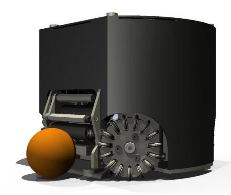
At the beginning of this year, the mechanical team's main tasks were improving our two fleets of six robots each, designed in 2008 and 2011. The major difference between these fleets is the encoders and chipper on the 2011s. The mechanical team spent most of their efforts on improving the robustness of the 2011 fleet's drive modules (Figure 1), troubleshooting the 2008 fleet, and working on designs for the 2014 prototype. In addition to these projects, the mechanical team also worked on a variety of smaller improvements such as a new ball sensor mount, improved shells, and fixing encoder issues. For more information on designs and progress from this year and a detailed explanation of all subassemblies, see: http://wiki.robojackets.org/w/RoboCup#Mechanical.
2.1 Drive Plate Standoff
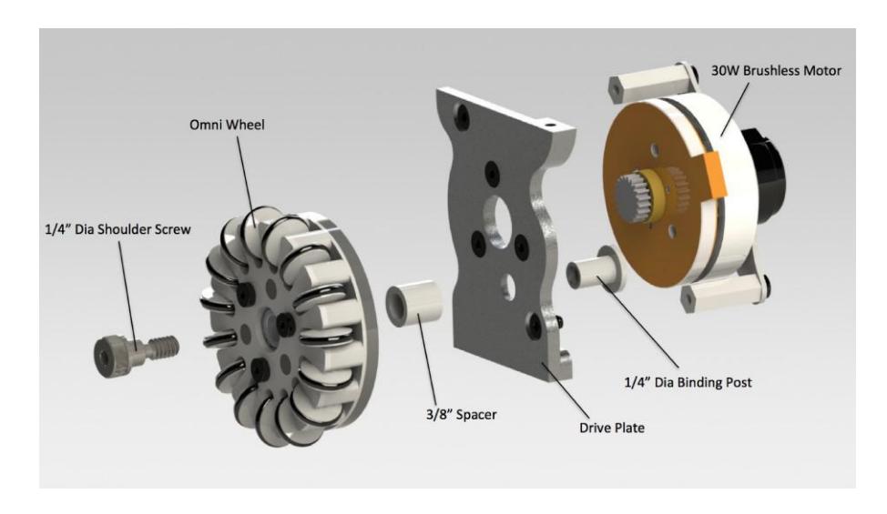
The drive plate standoffs supporting the omni wheels have presented the biggest issues with the 2011 fleet. These standoffs are very important because they align the gears on the drive plates with the gears on the omni wheels, letting the wheels move freely without scraping the sides of the drive plates. These standoffs were originally welded onto the drive plates. However, due to the continuous torque on the welds, they began to snap, causing the omni wheels to detach during gameplay. Our initial solution of using a thread-locking adhesive on custom threaded standoffs did not overcome the excessive torque. It also introduced difficulties with setting the omni wheel the right distance from the drive plate, since the standoffs could be screwed in at a range of depths before being locked into place. A more robust solution was clearly necessary.
For our current solution, we replaced the standoffs with a combination of a binding post and a spacer. The binding post is pressed through the drive plate and the spacer fits over the barrel. The same shoulder screws from the previous design can be used to mount the omni wheel onto the plate by screwing directly into the binding post. With this design, the same drive plates can be used after a simple counter-bored hole is added. This is also a much eaiser fix in competition because all we need is a few spare parts. This solution has already proven adequate, however, a more elegant solution for future prototypes will be implemented.
For the 2014 prototype, we have decided to design a drive plate with the standoff built directly into the structure. The new design will provide a solid structural base, and will eliminate the problem of breaking standoffs. It also fixes the imprecision of the standoff length, which can cause gear disengagement or rubbing between the drive plate and omni wheel. The standoff feature will have nearly identical geometry to the separate standoffs previously used. They will be tapped with the same 10-32 thread so that the same shoulder screws may be used to secure the omni wheel. The primary downside to this drive plate design is that it will waste a significant amount of material in its fabrication. We decided to accept this cost for the sake of the reliability and simplicity of the drive module.
2.2 Improved Chipping Precision
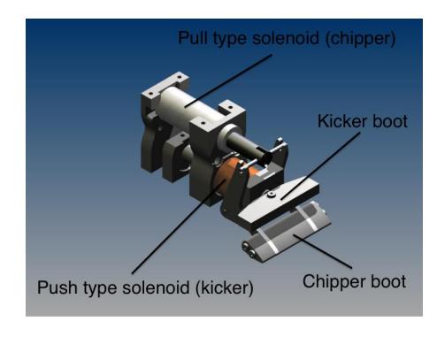
We have redesigned the chipper in our upcoming prototype (see Figure 2). The chipper arms have a lower pivot point, allowing for chipping with greater control and range. In addition to improving the chipping height, the updated chipper, in conjunction with the new dribbler, allows us to dribble on the chipper boot. This allows the potential of a ball centering mechanism by only altering the profile of the chipper boot, greatly improving our ball control. Besides those redesigns, we'll stick with the same tubular pull-type solenoid and the same design for the chipper arms. The chipper arms were designed so that the direction of motion of the arms at the time of impact is perpendicular with the ball's surface. This ensures that as much energy as possible from chipping goes towards the translational energy of the ball, rather than rotational.
2.3 Ball Sensor Assembly
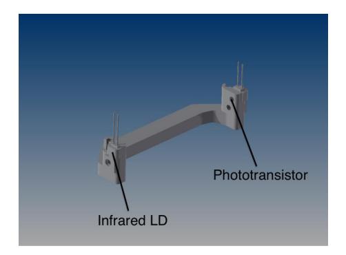
The ball sensor assembly uses an LD emitter in line with a phototransistor (see Figure 3). When the ball is present, the line is broken. Currently, the emitter and sensor are inserted into circular holes on opposing sides of the boot and fixed into place with hot glue. The issue with this design is that, over time, the glue ceases to hold the wires in place and the sensors fall out or become misaligned. In collaboration with the electrical team, we have designed a new LD fixture that will not require additional adhesives. The boot has a slot that will fit the LD fixture, with a separate bracket that will screw into the boot to hold the LD into place. With this design, the ball sensors may be adjusted or replaced easily, without sacrificing reliability.
2.4 Dribbler
For our 2014 prototype, the dribbler mouth width will be reverted to the size it was on the 2008 fleet. On the 2008 fleet, the dribbler mouth was 2.83" in width, but in the 2011 model, it shrunk to 2.58". The problem with the reduced size is that it makes it harder for the robot to receive the ball in its mouth. The other option for widening the dribbler mouth is to re-orient the angles of the wheels. However, in their ETDP from 2013, the ZJUNlict team cited [2] that a wider dribbler mouth in fact yields less precise shot control. Our compromise will be to stick with the 2008 dimensions for the 2014 prototype design. Beyond widening the dribbler mouth, not much else will be altered. We will still use the 12V DC brushless servo motor and since our 2011 dribbler produced the torque we wanted on the ball, we'll keep the dribbler gear ratio at 1:1.75.
3 Electrical
The main focus of electrical this year was the 2014 control board prototype. The prototype features bootstrapping concepts in a new motor driver circuit, a seven segment display for onboard status updates, and a new control system for power cycling. The main benefits of these features include increased board space, reliability, and safety. Our two other focuses this year were the usage of RFID technology for robot identification and the expansion of kicker board subsystems to accelerate and automate the charging and discharging of the capacitors.
3.1 Motor Drivers
The 2011 control board has had issues in the past with FETs and FET drivers failing due to overcurrent and shoot-through [5]. Because motors are switched quickly, they experience a large $\frac{dI}{dt}$ , which causes the inductive windings to create a large transient current in the opposite direction to normal current flow. This current can destroy FETs and can sometimes propagate all the way to the FET drivers. This problem was observed whenever the robot was commanded to make very fast changes in velocity. To combat this effect, the new control board features transient voltage suppressors (TVS) that block large voltage spikes from the motors. Each FET also has a second redundant body diode to ensure that the body diode inside the FET does not break down. More line capacitance was added to help absorb transients as well.
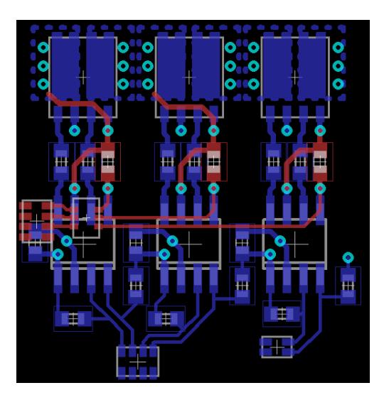
Furthermore, we have faced the issue of power efficiency and excessive space consumption for a few years now. This year we decided to tackle this with a brand new design. We decided to move away from the traditional PMOS/NMOS configuration in favor of a dual N channel MOSFET. Our reason behind this decision was based around the inherent inferiority of the PMOS device. The N channel MOSFET is an intrinsically more efficient device because it uses electron mobility instead of the P channel's hole mobility, which is faster and less resistive. This results in numerous advantages for the NMOS including a lower Rds(on), lower parasitic capacitance, lower production cost, faster switching speeds, and a smaller footprint. Technology has advanced to the point where the NMOS has surpassed the PMOS in almost all aspects such that the PMOS becomes the limiting factor of any circuit.
The chip we chose for our dual N channel MOSFET was selected based on its low Rds(on), low cost, and heat efficient PG-TDSON-8 footprint. One disavantage we faced in this design was the limited selection of dual N channel MOSFETs. This led to a less efficient high side of the circuit. We hope that selection will increase as the part becomes more popular. The other disadvantage of using two NMOSs is the complexity of driving the circuit. In an NMOS, current flows from drain to source and the gate voltage has to be above the drain. On the low side, this is not a problem, as the source is connected to ground, and the gate to the supply (14.8V). When placed on the high side of a circuit, the source raises up to the supply. The gate needs to be higher than the source, but the source is already connected to the highest voltage available. To drive this dual
N channel MOSFET, a bootstrap circuit was implemented. The circuit uses a concept known as "bootstrapping" to raise the gate up above the supply. Using a half-bridge gate driver, a boot diode, and a boot capacitor, an extra charge is held from the supply and then added on top of the supply to bring the gate from 14.8V to ~25V, essentially pulling it up by its own bootstraps [1].
3.2 Ball-Detection Sensors
In previous years, we detected ball possession with a break-beam sensor under the dribbler bar. This sensor consisted of an infrared LED and a phototransistor. Previously, this sensor was frequently broken by contact with other robots because the sensors had to be in an exposed location. A failure of the ball sensor gave the same indication as ball possession, requiring heuristics on the control computer to determine whether a particular robot's ball sensor was damaged. The new mechanical design better protects the sensors. The new electronics can detect four classes of ball sensor failure: emitter open, detector open, detector shorted, and dazzling (excessive ambient light). If the emitter or detector is mechanically damaged, the most likely result is an open circuit which can be detected and reported, allowing the robot not to be chosen for ball-handling tasks during gameplay and to be replaced at the next opportunity.
To compensate for varying ambient light, alternating measurements are made with the emitter on and off. If the emitter-on measurement is unexpectedly high, the most likely cause is excessive ambient light, and the ball sensor will not report constant possession. By detecting ball sensor failure, we can avoid certain cases where a robot attempts to handle a ball that it does not actually possess. At RoboCup 2012 in Mexico City, our ball sensors had a hard time dealing with the large amount of infrared light from the field lights. We spent a lot of time attempting to calibrate the sensors against the unusually high ambient IR light, but had problems in shielding the photodiode, as the ambient IR light was almost as intense as the IR LED. Additionally, scattered IR light off the ball from our LED sometimes created false positives.
This year, we have switched from an LED to a VCSEL (Vertical Cavity Surface Emitting Laser) to do ball detection. This allows us to recess the photodiode further back into the dribbler assembly and reduce the effects of ambient or scattered IR light. Rather than just emit a single beam from the VCSEL, we use an LFSR (Linear Feedback Shift Regsiter) to pulse the beam in a quasi-random fashion. Since the receiver knows what the bit sequence being generated by the LFSR is, it can look for that pattern and reduce false positives from external light. The quasi-random nature of the sequence makes it almost impossible for an ambient source to match closely enough to cause a false positive. This sequence can be extremely fast, as VCSELs can pulse for as short as 200 picoseconds, while LEDs can only pulse down to about 500 nanoseconds. In addition to a more precise source, a new photodiode with a higher dynamic range was also chosen.
3.3 On-board Status Display
To further improve the simplicity of our design, we removed our LED array in favor of a seven segment display. While the LED array offered the ability to show multiple pieces of information at once, it could only display information using 5 LED's. This in turn caused any additions to be added as blinking patterns, which proved to be hard to read. The seven segment display offered a much clearer presentation of information. Errors are now given as alphanumeric values. For example, a display of 'H' would indicate that a hall sensor fault has occurred. The display cycles through all of the errors in order of importance. To further usability, we have also added a label the robot shell to help decipher status codes.
3.4 Robot Identification Number Selection
One of the issues that we have dealt with in past years has been the accessibility and visibility of the Robot ID Number dial. Traditionally, we used the dial on the control board which allowed us to select an ID between 0 and 15. Changing the robot number involved removing the shell, getting low to the ground, and attempting to determine the selected number—which was moderately indistinguishable—before turning the dial. The solution we chose was to add additional circuitry in order to allow the robot to generate an ID number based on the shell it was wearing. We chose to implement an RF-based solution that utilizes 125kHz passive RFID tags embedded in each shell. Upon power-up, the robot will read the serial number off of its shell's tag and compare it to a lookup table in order to obtain the robot's ID number. In the event that a tag is not found, the robot will default to the previous method of using a dial to control the robot number. This fallback enables testing without the shells. The RFID circuit utilizes the clock frequency generated by our Spartan 3E FPGA. We also plan to print antennas for the reader on custom designed boards. Attachment points centered around the chip will then be added to allow for the antenna to exist external to the main board.
3.5 Kicker
The 2013 kicker board was an excellent advancement in our kicking ability. With that completed, we've refocused our efforts of future improvements. We identified two major issues so far that we wished to tackle, each focused around the capacitors. The first of the two issues was the time needed to charge the capacitors. In our current arrangement, we have a charge time of roughly 3 seconds. We've seen the ability of other teams to charge in much shorter times. We believe the reason for this is that our flyback converter is too inefficient. We looked into changing this to a buck-boost converter or redesigning our flyback converter. However, this has been pushed back in favor of our 2014 control board because the next kicker board isn't scheduled to be completed until 2016.
The second issue we faced was the method of discharging the capacitors. In our 2011 design, we added a discharge switch, which would dump all remaining energy in the capacitors into the solenoid. Since then, we have moved away from the discharge switch in favor of a more passive system. We wanted functionality that would allow the capacitors to discharge automatically whenever the robot was turned off. We also wanted to move away from the method by which the power is discharged through the solenoid due to the inherent danger of the robot kicking while being handled. The solution we proposed capitalized on the extra space that we had on our kicker board. Using a relay and a series of bleed resistors, we were able to create a system that would dissipate capacitance to safe levels within roughly 5 seconds. The current active system will remain in place since it offers a quick method of testing the kicker during routine maintenance.
3.6 Battery
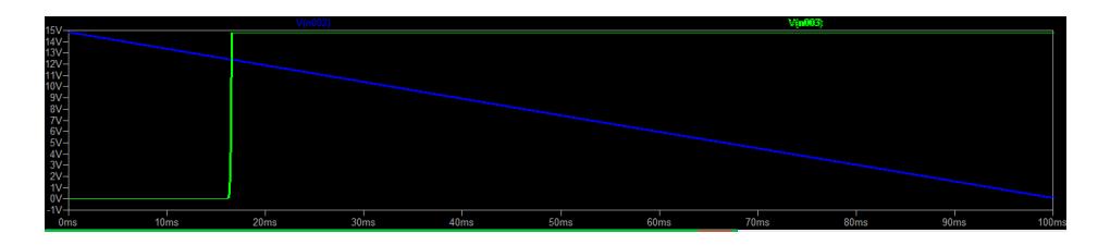
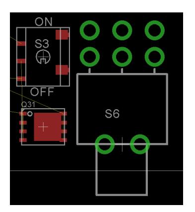
This year, to eliminate the need for a switch of such massive size, we introduced a power PMOS into the circuit (see Figure 5). Our previous switch was the direct controller of the power line, which required it to be large enough to handle the large current and voltage. In our new system, a switch toggles the gate of the power PMOS, which now handles the on and off cycles of the robot. Because the switch is no longer controlling the entire power line, we were able to add a much smaller surface mount switch. The removal of the large switch will increase the safety of the robot, given the switch's large live wire prongs. The change will also generate more board space for future revisions (see Figure 6).
4 Software
The main area of focus for the software team this past year has been precision control of robot motion. In the past, the robots have had a significant amount of path-tracking error and overshoot whenever the target path turns sharply or ends. This has held back the rest of the software stack because the high-level logic ultimately becomes a set of motion targets for the robots. With imprecise movements, the robots perform poorly as a team, regardless of how effective the soccer strategy is. The two main deficiencies in the old motion system were the path planner and the trajectory-tracking controller.
4.1 Kinodynamic Path Planner
Last year's path planner used bidirectional RRTs (Rapidly-exploring Random Trees) to search the field for open pathways from robots' current positions to their destinations. This worked well for finding collision-free paths, but did not consider robot dynamics, leading to issues when it came time to actually execute the paths on real robots. It also made it difficult for higher-level logic to be able to reason about the system and predict when robots will get to their destinations. This year's iteration of the planner is based on the previous design, but each node in the RRT contains a velocity vector in addition to the position vector that was there before. In addition to storing more data, the RRT also must be grown in a different way. The basic technique of choosing a random point on the field, then attempting to grow the tree towards it, is the same. However, robot dynamics must be considered here as well. The non-kinodynamic RRT simply used 2D distance when finding the closest node to a given random point. The new planner chooses the node from which the robot can get to the destination point in the least amount of time, but not necessarily distance. The end result of running the kinodynamic planner is that the path is returned as a function of position given time [3]. Assmuning that the robots can accurately follow the generated paths, this results in a much more predictable system than time-ignorant paths.
Due to the increased processing time required by the new planner, some other changes had to be made to the system to keep it running effectively. Previously, each robot's path was recalculated at every iteration of the main runloop in the soccer program. Because the planner was quick to execute, this simple solution worked well and did not cause any issues. The new planner, however, would decrease the framerate of our processing code if it was run every time. The scheduling for the new planner is currently under development, but right now the paths for two robots are calculated at each timestep, which means that it takes three frames to replan for the entire team. Since soccer is running at about 60Hz, this is a minor delay and has not affected our system's performance.
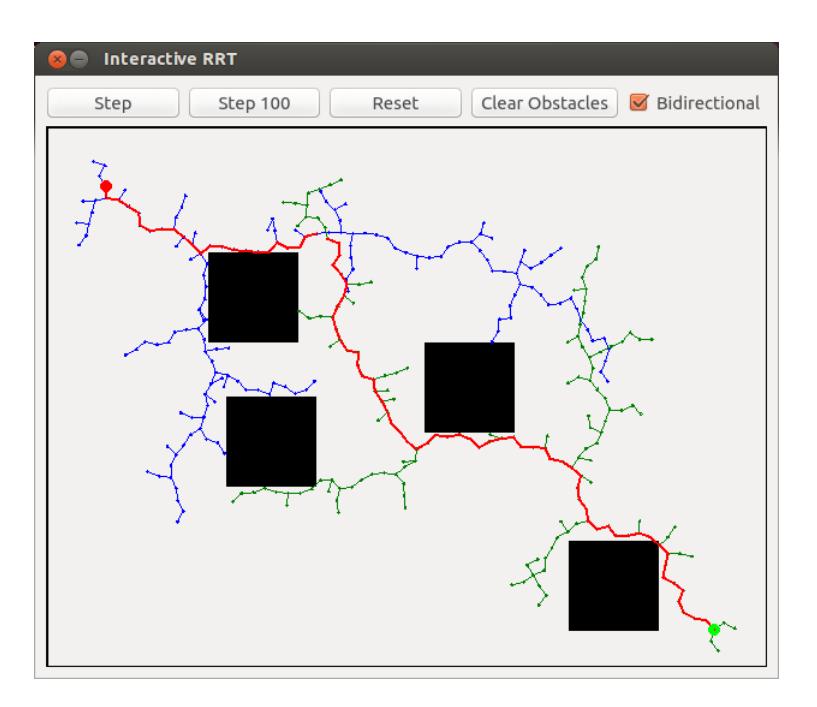
In order to help visually debug some of our RRT code and gain better insight into how it works, we have developed an interactive RRT viewer/applet. The applet uses the same back-end RRT implementation as our robot control code and has a few buttons for growing the tree and adding obstacles to the field for the planner to navigate around. It currently has several limitations, most notably that it does not yet support our newer kinodynamic RRT implementation. Future development will add these features to make it an even more powerful tool. Figure 7 below shows a screenshot of this program, which can be downloaded from our GitHub page at https://github.com/RoboJackets/rrt.
4.2 Improved Motion Control
In the past, the software responsible for the robots' motion was fairly primitive, resulting in poor performance on the field. It has been one of the main goals this year to improve on our motion control so that the robots' execution is much more reflective of the plans generated by the high-level soccer strategy code. The new system provides for much-improved predictability of the system, allowing soccer plays to be more intelligent in their decision-making.
The previous implementation of the motion controller was concerned only with the robot position when following paths. By neglecting velocity, our software gave up the ability to estimate when a robot would complete its assigned path and be available for a pass or be in line to shoot at the goal.
As explained in the above section on path planning, incorporating time and velocity into our motion system has been a key part of this year's enhancements. Complementing the velocity based paths is our system's new trajectory-tracking motion controller that seeks to reduce tracking errors in both position and velocity. The system is based on ideas presented in [4].
4.3 Open Source
At last year's competition in Eindhoven, all of the SSL teams met to discuss the progress of the league and potential changes or initiatives that could enable teams to progress more quickly in trying out new ideas. A major point brought up in the discussion was that each team duplicates much of the work of other teams in order to get their robots up and running. Each team has to design and implement things such as path planners, motion controllers, radio communication protocols, a soccer user interface, and high-level soccer strategy. Because of the competitive nature of the sport, teams keep their designs private to avoid giving too much advantage to others. However, the league would like to see more innovation and technological advances, which would be greatly benefitted by a more open culture of idea-sharing among teams. If ideas can be more openly shared, teams will spend less time duplicating common components and have more time to spend experimenting with new ideas and advancing the league.
This idea resonated with our team, so we made the decision to open-source our codebase. We hope new teams that need some inspiration for their software can look to ours for some ideas and see an example of how to implement different parts of a working RoboCup software stack. In addition to hopefully benefitting other teams, open sourcing our codebase has also helped our own team to become more organized. Some areas of the codebase were fairly poorly documented, making it difficult for new members to get up to speed on the methods and concepts used. Having our work available for download to the entire world puts more pressure on the team to make sure that the work done is organized, modular, and well-documented.
Our project can be found at the following URL on GitHub: https://github.com/RoboJackets/robocup-software
References
- Fairchild Semiconductor. Design and Application Guide of Bootstrap Circuit for High-Voltage Gate-Drive IC, 2008.
- Li Fang, Hangjun Tong, and Rong Xiong. Yonghai wu, yue zhao, yifan shen, chuan li.
- Steven M LaValle and James J Kuffner. Randomized kinodynamic planning. The International Journal of Robotics Research, 20(5):378–400, 2001.
- Yong Liu, Xiaofei Wu, J Jim Zhu, and Jae Lew. Omni-directional mobile robot controller design by trajectory linearization. dynamics, 2:2–2, 2004.
- Robojackets RoboCup SSL Team. Robojackets robocup 2011 team description paper. Technical report, Georgia Institute of Technology, 2011.