SKUBA 2014 Team Description
Kanjanapan Sukvichai, Thanakorn Panyapiang
Faculty of Engineering, Kasetsart University 50 Ngamwongwan Rd, Ladyao, Bangkok, Thailand
Abstract This paper gives a brief description of Skuba, A RoboCup Soccer Small Size League robot team. Skuba system is designed under the RoboCup 2014 rules in order to participate in the RoboCup 2014 which hold in Brazil. The problem we encounter last year is the new robots which was built last year is very hard to control. So, this year we mainly focus on solving this trouble.
1 Introduction
Skuba is a Robocup Soccer Small Size League robot team from Kasetsart University, Bangkok, Thailand. The team was established in 2002 and first participated in Robocup Soccer Small Size League in Robocup 2006, Germany.
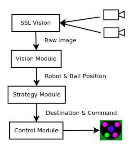
Skuba system is composed of two main components: robot and software. Robot is consist of several hardware, for example, kicker board, motors, capacitors and mechanical parts. All of these components are operated by main electronic board. Software system use data from global vision software, SSL Vision, to make decision and choose a suitable strategy for specific situation then send commands to robots via wireless signal.
The next section will explain about our robot mechanical and electrical design. In section 3, we describe the software architecture and briefly explain detail of its components.Finally in the last section, we will present the conclusion.
2 Robot Hardware
(placeholder for section introduction)
2.1 Hardware
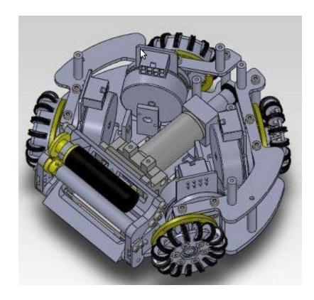
The robot has four omni-directional wheels driven by 50 Watts Maxon flat brushless motors. Dribbling device is a round bar cover with silicone tube connect to 30 W Maxon EC brushless motors. The dribbler can run up to 37,700 rpm and cover the ball about 20 percent of diameter. The kicker consists of flat-kicker and chip-kicker. The flat-kicker uses solenoid to kick the ball with ball speed up to 14 m/s. The chip-kicker uses flat solenoid attached with a 45 degree hinged wedge on the bottom of the robot. Both kickers are driven by four 1200F 250 V capacitors. Kicking devices are controlled by separated kicker board below the middle plate. Fig.1 illustrates 3D model of our robot[1].
2.2 Controller
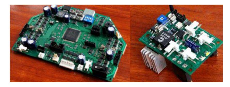
The robot hardware is controlled by a single-chip Spartan-3 FPGA from Xilinx. The FPGA contains 32-bit microprocessor core run at 30 MIPS and interconnected peripherals. This embedded processor executes the low level motor control loop, communication and debugging. The brushless motor controller, quadrature decoder, kicker board controller, PWM generation and onboard serial interfaces are implemented using FPGA logic gates. The robot receives control commands from the computer and sends back the status for monitoring using a bidirectional 2.4GHz wireless module. A Kicker board is a boost converter circuit using a small inductor. This board is separated from the main electronic board. Fig.2 show the main electronic board and kicker board.
3 Software Architecture
The overall software architecture is shown in Fig.3. The software system consists of several modules organized in multi-layer. The Design of software system is based on Cornell Big Red's software.
3.1 Vision Module
Vision module extracts robot's velocity from vision data receive from SSL Vision[2],shared vision system for Robocup Small Size League, and also predicts future location of robots and the ball. Our total system latency, measuring from the period between command velocity and raw velocity, was approximately 133 ms (8 frames). When our robot move at the maximum speed, that is up to about 3.5 m/s, the distance between real robot position and the robot position from vision will increase up about 47 cm. In order to fix this error we need to do position estimation for all robots by applying the Kalman filter. For opponents and the ball, two states Kalman filter is applied to predict opponent robots and ball location with more accurate location.
3.2 Strategy Module
Main role of Strategy module is similar to football team manager. The module use vision data from Vision module to analyse the current environment in order to select the suitable tactic and formation which are the most suitable for present situation. The structure of this module is based on STP framework[3]. The module contains several Plays which store in Playbook, a collection of Plays, when Play was executed it call the Role of existing Position (For example, Goalkeeper and Defender). Then the Role runs Skill that keep in Skillset, for related Role. The architecture of Strategy Module illustrate in Figure 5.
3.3 Control Module
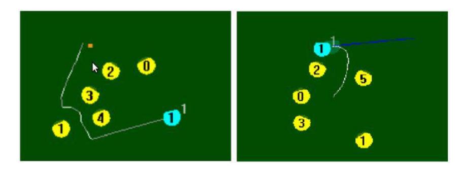
After Strategy module select the most suitable tactic and formation for the team at current situation, the command will be sent to Control module in format of field coordinate and some specific command, for instance, dribbler and kicker command. For field destination, the module will find the path that the robot can navigate from current location to the target destination, which receive from Strategy module, by using Path Planning algorithms. There are two path planning algorithms,Rapid-Exploration Random Tree(RRT) [4] and Subgoal, that we implement in our system. Fig.4 shows paths generate by RRT algorithm and Sub-goal algorithm. After path planning was finished, the module also take responsibility to generate robot's velocity profile. Moreover, this component also uses vision data from Vision Module as a feed-back for Closed Loop control.
3.4 Simulator
Simulator is developed in order to simulate robot behavior. The Simulator receives a sequence of packets which is identical to packets that are sent to real robots then calculates some simple physics and returns the coordinate of objects in the field to the software as same as the VisionServer does. Our Simulator is entirely independent from AI System which is capable of simulating all the field objects and latency of the system.
4 Conclusion
Last year, we built the new robots with new motors and mechanical design and found that the new robots is harder to control than the previous version which cause our team doesn't perform well in Robocup 2013. So this year we concentrate on solving this problem in order to improve our performance in Robocup 2014.
5 Team Member
This year, Skuba team is consist of this following members:
- Supervisor: Kanjanapan Sukvichai
- Team Leader: Thanakorn Panyapiang
- Computer Engineering: Krit Chaiso, Jaktip Yodsri, Tachin Srisombat, and Tisana Kitsahawong
- Electrical Engineering: Teeratath Ariyachartphadungkit, Suppawit Inhorm
- Mechanical Engineering: Sutinai Tanalerkchai
References
- Panyapiang, T., Thanomyart, R., Sukvichai, K., Thanalerkchai, S.: Skuba 2013 team description paper
- Zickler, S., Laue, T., Birbach, O., Wongphati, M., Veloso, M.: Sslvision: The shared vision system for the robocup small size league. In: in RoboCup 2009: Robot Soccer World Cup XIII, ser. Lecture Notes in Artificial Intelligence
- Browning, B., Bruce, J., Bowling, M., Veloso, M.: Stp: Skills, tactics and plays for multi-robot control in adversarial environments. IEEE Journal of Control and Systems Engineering 219 (2004) 2005
- Lavalle, S.M.: Rapidly-exploring random trees: A new tool for path planning. Technical report (1998)