Stanford Robotics Club 2014 Team Description
Payton Broaddus, Ben Johnson, Brian Jun, Rohan Maheshwari
Stanford Robotics Club, Stanford University, Stanford CA USA
http://roboticsclub.stanford.edu/
Abstract This paper describes the Stanford Robotics Club's RoboCup Small-Size League team. Low-cost brushless DC motors are driven with sinusoidal commutation with an adjustable phase offset to account for manufacturing variations. A linear motor kicker is presented which is expected to have significantly better efficiency than current solenoid designs.
1 Introduction
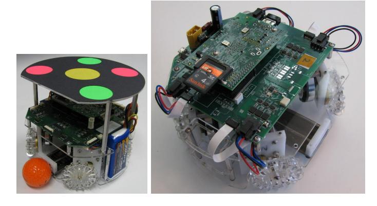
The Stanford Robotics Club is a student group started at Stanford University in the fall of 2012. Members include undergraduates and graduates from a variety of majors. This RoboCup Small-Size League team is one project being developed by the club. We have built prototype robots to validate the design, and we will build a fleet of seven robots (six players and one spare) for competition. Two generations of prototype robots are shown in figure 1.
2 Robot Hardware
All robots on the team are identical. Each has four omni wheels, one kicker, a protective shell, and a lid matching the league's standard vision pattern. Each robot is powered by two two-cell lithium polymer battery packs wired in series.
The majority of robot components are designed to be low-cost and easy to fabricate. Most components have been prototyped in laser-cut acrylic and will be remade in waterjetted aluminum for final production. No CNC-milled parts are required, although modified off-the-shelf gears are used in the drivetrain. The conversion from laser-cut to waterjet parts will require few or no changes, solely to account for different tolerances in the fabrication processes.
2.1 Size and rule compliance
All robots fit inside a cylinder 179mm in diameter and 149mm in height, as measured on a hard surface with the wheels rotated to achieve the maximum robot height. At most 19% of the ball's area as seen from above will be inside the robot's convex hull. The ball's motion is limited by stops to prevent the ball from moving too far into the robot.
2.2 Electronics
Most of the robot electronics are on a single printed circuit board which contains:
- Motor drivers.
- An XC6SLX9 FPGA for timing-critical motor control.
- A MPU6000 six degree-of-freedom inertial measurement unit (IMU).
- Connections for off-board sensors, batteries, and kicker electronics.
Each motor driver consists of three L6743Q MOSFET drivers and three STL40DN3LLH5 dual MOSFETs per motor. A current sense amplifier and ADC monitors the current through the lower half of two half-bridges on each motor, allowing the current through all three motor phases to be known on a cycle-bycycle basis. This is intended to allow field oriented control to be implemented in the future to achieve precise control over torque.
A Raspberry Pi single board computer is mounted on top of the control board. The Raspberry Pi was chosen to simplify board design while providing convenient debugging facilities and enough computing power for possible future features like IMU-based motion control.
The radio is a Texas Instruments CC1101, which can operate over a wide range of frequencies include both European and US license-free bands.
An Invensense MPU-6000 inertial measurement unit is included to support future development of on-board motion control in a field coordinate system rather than in robot-oriented coordinates.
The robot's identity is determined by a replaceable lid on top of the robot. While the vision system can identify the robot by the pattern of dots on the lid, the firmware identifies the robot by a conductive pattern attached to the bottom of the lid. The pattern consists of a thin sheet of metal partially covered by a laser-cut polyester mask. A set of spring pins extend from a small circuit board near the top of the robot to contact this pattern. The pattern cut into the mask is detected by continuity between signal pins and two ground pins. The set of patterns is chosen to allow the robot to be correctly identified even if any one pin fails to make contact and for a missing lid to be detected. This design makes changing robot teams and identities very fast at half-time and reduces the opportunities for human error that would result from using a switch on the control board.
2.3 Drivetrain
The performance goals for the drivetrain are a maximum speed of 4 $m/s$ and a maximum acceleration of 5 $m/s^2$ with a mass budget of 2.5kg. The actual achievable speed and acceleration will likely be limited primarily by traction between the wheels and the carpet. Since the prototype wheels are laser-cut and have poor traction, the performance of the final wheels is unknown but is expected to be significantly better than for the prototype.
The motor is coupled to the wheel by brass gears with a gear ratio of 1:2.2. Each wheel is an omni wheel with 15 rollers.
2.4 Motors
The motors are off-the-shelf quadrotor motors, model AX-4006D, which are modified by changing the connections of the windings from a delta to a wye configuration while keeping original windings. This modification reduces the speed constant from 530 $RPM/V$ to 300 $RPM/V$, allowing the use of a smaller gear ratio than would be possible with the stock wiring. This motor is similar in size to the Maxon EC-45 which is commonly used in the Small Size League, but is significantly cheaper ($31 compared to $100), has lower internal resistance (0.8Ω compared to 1.2Ω), and is easier to modify.
This motor does not have internal hall effect sensors. An incremental optical encoder attached to the back of the rotor provides high resolution relative position measurements for commutation and speed control. The encoder consists an Avago AEDR8300-1K sensor and a custom codewheel with 256 lines per revolution cut from an 8000DPI photoplot and mounted on a reflective disc. The arrangement of these sensors is shown in figure 2.
The position of the sensors relative to the stator windings varies among motors due to manufacturing variation. We drive the phases at points sampled from three sine waves 120° apart but with an additional phase offset determined by the physical position of the sensors:
$$V_A = V_{peak} \sin (\theta_{sensor} + \theta_{offset})$$
$$V_B = V_{peak} \sin (\theta_{sensor} + \theta_{offset} + 120^{\circ})$$
$$V_C = V_{peak} \sin (\theta_{sensor} + \theta_{offset} + 240^{\circ})$$
$\theta_{sensor}$ is the magnetic position of the rotor as measured by the hall effect sensors and the optical encoder. $\theta_{offset}$ describes the relationship between the sensors and the stator windings. $\theta_{offset}$ is determined by an automatic alignment process which attempts to maximize speed while applying a constant voltage magnitude. With the robot held off the ground, a DC current vector is applied to the stator to bring the rotor into a fixed position relative to the stator. The encoder position (relative to its arbitrary reset position) now indicates the stator current phase which is approximately 90 degrees away from $\theta_{offset}$. Sinusoidal commutation is then applied to the motor while $\theta_{offset}$ is adjusted over a small range and the $\theta_{offset}$ which produces the maximum speed is recorded. This process is repeated for each motor. The alignment needs to be performed only once after the encoder counters are reset, which happens during FPGA reconfiguration. The $\theta_{offset}$ for each motor is stored in the FPGA so firmware restarts do not require realignment.

2.5 Kicker
The standard kicker design in the Small Size League is a solenoid powered by a capacitor bank. This design is simple but has several drawbacks:
- Large mechanical stresses due to high acceleration.
- Difficult mechanical integration due to the size of the capacitors.
- Poor efficiency due to the long travel of the armature.
- Difficult electrical design due to the large currents required.
The force exerted by a solenoid decreases with the displacement of the armature, leading to low force near the beginning of travel and exceedingly high force near the end of travel.
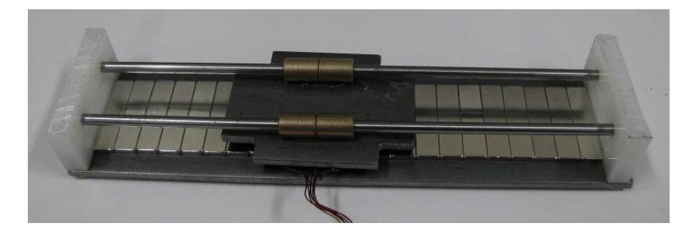
We are developing a different type of kicker based on a custom permanent magnet synchronous linear motor. The kicker consists of a stator and a forcer. The stator is two steel plates, each with a row of magnets having alternating poles along the direction of travel. The forcer slides along rails with small linear bearings and contains three coils. High-flex-life wires connect the forcer coils to their electronics.
The design goals are:
– Maximum final speed: 8 $m/s$
– Travel distance: 10cm – Peak current: ≤50A – Peak voltage: ≤100V – Forcer mass: 45g – Efficiency: ≥15% – Recharge time: ≤1s
To achieve the designed travel distance, the average net force is 15N and the travel time is 23ms. Efficiency is defined as kinetic energy in the ball divided by electrical energy supplied to the kicker.
3 Software
(This section is continued in subsections below.)
3.1 Log File
To aid testing and development, the first part of the software system that was written was the logging facility.
A log file contains a sequence of messages, each with an associated time and type. At this level, a message is treated as a binary blob with meaning only to the subsystem which read or wrote it.
The log file format has these design goals:
- Fast sequential writes: The writer is able to write entries rapidly to the end of the file. It is not necessary to append to an existing log file, as it is expected that a log file is only written once. The writer is able to write arbitrarily large log files without keeping in memory a correspondingly large amount of indexing data.
- Fast random-access reads: The reader can read sequentially or semi-sequentially from the log file. The reader can seek to arbitrary locations in the log file.
- Indexing: The reader is able to quickly load any necessary indexing data from the log file. Reading arbitrary messages doesn't require reading the entire file.
- Crash tolerance: If a writer crashes while writing the log file, only unwritten messages are lost. Indexing data for messages which have already been written is not lost.
Most log messages are serialized with Google Protocol Buffers [1]. A log file consists of a file header and a sequence of chunks. Each chunk consists of a chunk header, an index for that chunk, and a sequence of messages. Each chunk header starts with the total size of the chunk and the number of messages in it. This format allows a reader to quickly scan through a large log file and find the locations of all chunk headers and the total number of messages. The chunk headers and indexes for the entire file can be read quickly with minimal processing and without reading any message data.
When writing a log file, the number of messages per chunk is typically fixed, except for the last chunk. When the first message in a chunk is written, space for the chunk header and index is reserved. After the last message in a chunk is written, the writer goes back and writes the chunk header and index together.
3.2 Simulation
A simulator allows for rapid development and testing, and provides a reasonable approximation of the types of errors seen when operating real hardware. Vision data has added noise, the cameras can be misaligned, objects can disappear with a configurable probability, the ball can be occluded by robots, and vision data is delayed by a configurable latency to simulate processing delays. The simulation is based on the Bullet physics library.
3.3 Infrastructure
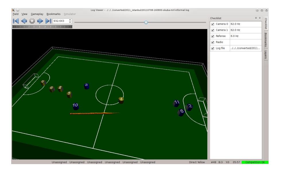
The software system consists of an infrastructure layer, which includes the user interface (figure 4), logging, and I/O; and a gameplay layer, which includes world state filtering, motion control, and strategy. Infrastructure, filtering, and planning is written in C++, while the top-level gameplay code is written in Lua. The Lua code executes under LuaJIT [2] which provides good performance with the convenience and brevity of a simple, dynamically-typed language. A console is provided to allow Lua commands to be given by the user to directly modify the state of the gameplay system. Configuration is stored in Lua files and can be automatically reloaded when edited to allow quick changing of parameters. Using a simple language like Lua allows test cases to be quickly written to validate parts of the system as they are developed.
The software allows the user to move through logged data while the system is running or to view recorded data from previous runs. The user can move to a specific time and can scroll through time at variable speed. All displays follow these controls, allowing every part of the display to be shown as it was at an earlier time.
Graphical annotations can be added to the field view by software at any level. These annotations are grouped into layers whose visibility can be toggled by the user. They are recorded in the log and can be viewed historically along with other log data. Arbitrary text can also be added to the log, which is displayed in a separate pane and can also be viewed historically.
A checklist is displayed in the main window which shows the status of major sources of data. This allows the user to quickly confirm that the system is ready to play a game by verifying that vision data from both cameras is being received at the proper framerate, referee data is being received, all data is being logged to disk, and all robots are communicating correctly. This removes the need for any lengthy manual confidence test before a game and helps identify network problems.
3.4 Latency Correction
Latency from camera vision is a problem for the robots to identify their current position and orientation. Without any latency correction, robots will constantly overshoot their target position and orientation, potentially not reaching the targets. To measure the latency, we send out a sinusoidal angular velocity command to one robot. Since the actual orientation of the robot would follow the shape of a cosine wave (integral of the sine wave velocity), we then calculate the delay of the camera's vision with:
$$delay = \frac{T}{2} + \frac{T}{2\pi}atan2\left(\sum \sin(t) pos_{obs}(t), \sum \cos(t) pos_{obs}(t)\right)$$
where:
delay=latency calculated (seconds)
T = period of the velocity sine wave (seconds)
$pos_{obs}$ ($t$) = camera's current raw position
The observed poses of the robots are extrapolated for the latency time according to the commands sent to the robots during that time.
3.5 Motion Control
Each robot moves along a path generated by a rapidly-exploring random tree (RRT) algorithm [3]. Robot paths may be planned individually, giving early plans more freedom of movement for high-priority tasks, or simultaneously, allowing robots to avoid each other throughout a lengthy plan. Simultaneous planning is achieved by defining the state space to include the pose of multiple robots at a single point in time.
Virtual obstacles can be created to prevent robots from entering or leaving a region of the field. This facility is used to implement some rules and performance tests, and to test the operation of planning techniques. If a robot is inside a virtual obstacle, the planner ignores that obstacle until the plan exits it, at which point the same obstacle cannot be re-entered.
A robot's path consists of a sequence of path segments, each of which is defined as position and velocity as a function of time. A PID controller on the central computer generates robot velocity commands based on the error between the path's desired pose and the robot's current pose as estimated by a Kalman filter. The robot velocity commands are rotated into each robot's frame of reference based on its predicted orientation at the time the command will be executed and then transmitted to the robots. If the path segment PID controller's error exceeds a fixed threshold, the robot is considered to have failed to execute the segment and a new plan is calculated based on the robot's current esimated pose.
A robot's path is not modified unless it fails to execute or unless the gameplay situation changes enough that the old plan is no longer applicable. In particular, the path is not regularly updated based on estimated pose since that would incorporate esimation errors into the plan.
Special-case velocity profiles can be planned for movement other than along piecewise-linear paths. For example, a robot lining up to kick the ball can pivot around the ball's center at a constant angular velocity, which is more easily achieved by directly generating velocities than by continually adjusting a planning target position. In this case, the effective size of the robot for obstacle avoidance purposes will be increased to guarantee enough space to execute the special movement without collision.
3.6 Gameplay
Gameplay is structured as a tree of behaviors. The team is, at the highest level, controlled by a state machine which responds to referee commands and selects a top-level behavior. Each top-level behavior delegates control of robots or groups of robots to further behaviors until a leaf behavior generates a command to be sent to its robots. The goalie is a special case, since the goalie behavior always applies to a particular robot, but the goalie can be given temporary new behaviors to allow cooperation with other players, such as if the goalie needs to clear a ball from its defense area by passing to another robot.
To obey gameplay-related rules, a state machine tracks referee commands and some basic state of the game and toggles a number of boolean constraints. These constraints include the presence of virtual obstacles on the field, such as a 1m diameter circle around the ball during stoppages, and behavioral constraints, such as selecting a different robot to touch the ball after a restart.
To allow the team's behavior to be quickly and easily modified, high-level behavior is controlled by Lua code which can be edited and reloaded without restarting the rest of the software system. This approach facilitates development of a variety of behaviors and also allows changes to be made during short timeouts with minimal disruption to the pace of the game.
4 Development Plan
The robots we have built so far are prototypes. Some parts are made of laser-cut plastic for rapid prototyping and will be replaced with waterjet-cut aluminum to increase robustness. The electronics and drivetrain design are finalized and the chassis and kicker designs are being finished.
The major development tasks that will happen by June 2014 are:
- Finish the kicker design and perform experiments to characterize its performance.
- Build the remaining robots to complete a team of seven (six playing plus one spare).
- Implement behaviors and constraints to cover all rule cases.
- Continue developing gameplay.
References
- Protocol Buffers - Google's data interchange format. http://code.google.com/p/protobuf/
- The LuaJIT Project. http://www.luajit.org/
- Bruce, J.; Veloso, M.; , "Real-time randomized path planning for robot navigation," Intelligent Robots and Systems, 2002. IEEE/RSJ International Conference on , vol.3, no., pp. 2383- 2388 vol.3, 2002. http://www.cs.cmu.edu/~mmv/papers/02iros-rrt.pdf