TIGERS Mannheim — Team Description for RoboCup 2014
Andre Ryll, Nicolai Ommer, Mark Geiger, Malte Jauer, Julian Theis
Department of Information Technology, Department of Mechanical Engineering Baden-Wuerttemberg Cooperative State University, Coblitzallee 1-9, 68163 Mannheim, Germany
Abstract This paper presents a brief technical overview of the main systems of TIGERS Mannheim, a Small Size League (SSL) team intending to participate in RoboCup 2014 in João Pessoa, Brazil. This year the team focused on improving the movement precision and reaction time and on establishing an overall more stable system in hardware and software. The new hardware from 2013 was reworked to fix some sever issues. The movement controllers were improved to gain a more precise movement and new control mechanisms were added to move the robot with less delay from the central software. Finally, the AI was transformed with focus on faster reaction.
1 Robot Specifications
| Robot version | 2013/2014 |
|---|---|
| Dimension | Ø178 x 148mm |
| Max. ball coverage | 12.3% |
| Driving motors | Maxon EC-45 flat 30W |
| Gear | 15 : 50 |
| Gear type | Internal Spur |
| Wheel diameter | 51mm |
| Encoder | US Digital E8P, 2048 PPR [1] |
| Dribbling motor | Maxon EC-16 30W with planetary gear head |
| Dribbling gear | 48 : 24 |
| Dribbling bar diameter | 12mm |
| Kicker charge topology | SEPIC |
| Chip kick distance | approx. 4m |
| Straight kick speed | max. 8m/s |
Table 1. Mechanical Specification
| Robot version | 2013/2014 |
|---|---|
| Dimension | Ø178 x 148mm |
| Max. ball coverage | 12.3% |
| Driving motors | Maxon EC-45 flat 30W |
| Gear | 15 : 50 |
| Gear type | Internal Spur |
| Wheel diameter | 51mm |
| Encoder | US Digital E8P, 2048 PPR [1] |
| Dribbling motor | Maxon EC-16 30W with planetary gear head |
| Dribbling gear | 48 : 24 |
| Dribbling bar diameter | 12mm |
| Kicker charge topology | SEPIC |
| Chip kick distance | approx. 4m |
| Straight kick speed | max. 8m/s |
2 Mechanical System
The mechanical system of our robots experiences some minor updates this year. The mechanical specifications are shown in table 1. Last year we completely redesigned our robots and found some problems during the competition in Eindhoven.
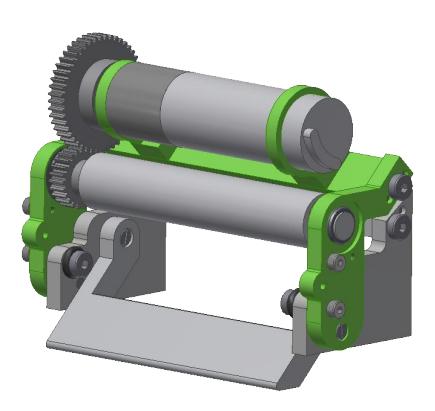
Chip Kicker Damping The first concern regards the chip kicker damping mechanism. If the ball is in front of the robot the chip kicking energy is transferred to the ball during the shot. It may happen that the chip kicker is falsely triggered with no ball in front. In this case the kick energy needs to be absorbed by the robot structure. We tried to quick-fix this problem by gluing some rubber on the shovel of the chip kicker but this was not a very enduring solution. Furthermore the chip kicker used bolts on the rotation axis and to stop the shovel. After a few shots the bolts were redounded and sometimes lost on the field. This year's version replaces the bolts by screws to mitigate this problem. The damping now consists of a O-Ring pushed over a screw, so no more gluing is required. The chip kicker and dribbler system can be seen in figure 1.
2 Mechanical System (continued)
Drive Train Another problem concerns the new drive train of our robot. Although it has proven to work quite well, it is not very maintainable. The wheel axis has been designed like a screw with a hexagon socket. This was planned to allow a rapid disassembly and assembly of the complete wheel. As the wheel axis were made of aluminum the hexagon socket was damaged easily, making it impossible to disassemble the wheel. We now replaced the hexagon socket by a recess one and changed the material to steel.
Regarding the maintainability we also changed the mounting of our drive train. Originally we mounted the bearing block and the encoder retainer separately to the bottom plate. Disassembling a complete drive train from the bottom plate required the two blocks to be unscrewed. Afterwards the encoder retainer was able to move and rotate freely at the end of the motor shaft, which leads to the encoder disc scratching on its housing. To mitigate this problem the encoder retainer is now mounted to the bearing block. The complete drive train can be disassembled by three screws and taken out as a whole. This also eases assembly and the production of spare replacement components.
Weight Reduction Further improvement this year is a weight reduction of the robot. The internal structure of our robot is mainly composed of steel struts and aluminum plates. It turns out that some of the struts are not required for stability and others can be replaced by plastic variants. The case is also very robust (1mm steel), which is not necessary because collisions should be a rare case and are treated as a foul. We are currently investigating case options which are lighter but still able to absorb a ball impact of 8m/s. We also changed the battery from a 4-cell variant to a 3-cell variant which weighs only half of the original. We need to investigate the durability of this battery, especially concerning the new field size. A larger 4-cell battery still fits in our new robot, so that it stays as an option. The main electronics board has also been redesigned to a lower total weight.
3 Electrical System
The electrical system of our robot experienced severe damage in RoboCup 2013. We had multiple motor cables burned to smoke and non-functional kicker barriers occurred frequently. The kicker boards had multiple exploded traces and burned components. Beside electrical issues we had a problem with the nRF24L01+ wireless modules [2] and the protocol we implemented for them. The main focus was thus to increase stability of the system and extend it by additional safety functionality.
3.1 Mainboard Redesign
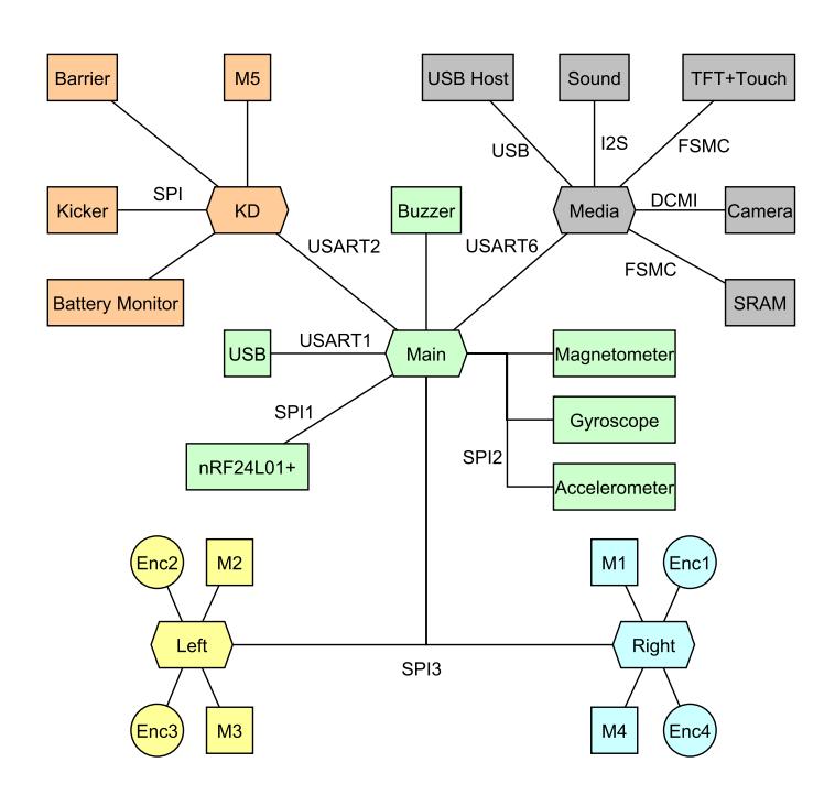
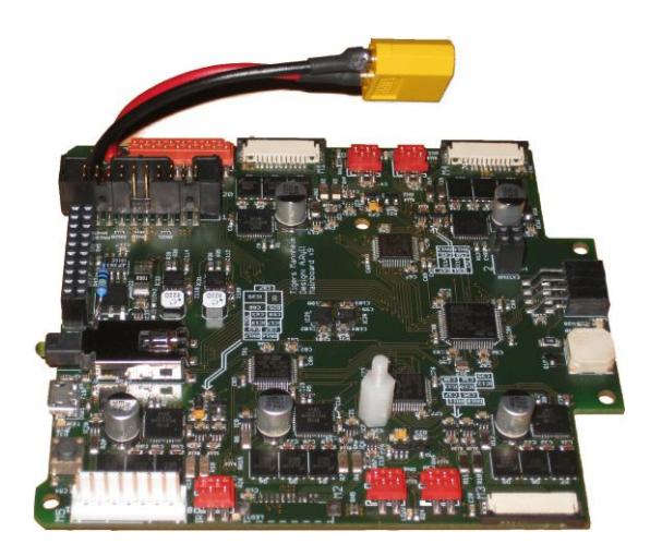
The mainboard has been completely redesigned this year. The greatest change is the use of dedicated microcontrollers for motor control. The complete system architecture can be seen in figure 2. Microcontrollers are shown as a hexagon. The assembled mainboard is shown in figure 3. The previous version only had the Main and the Media controller (both STM32F407 [3]). The main controller implemented velocity-based motor control and a software pulse-width modulation (PWM) algorithm. The old mainboard also equipped three ATmega coprocessors for voltage and current sensing.
The new mainboard removed all ATmegas and uses three additional microcontrollers (STM32F303, Cortex-M4 with FPU [4]) clocked at 72MHz, named KD (kicker/dribbler), Left and Right. Left and Right each control two motors. The PWM algorithm is now done with hardware timers, dramatically increasing their precision and reducing CPU overhead. The PWM frequency stays at 20kHz, but the resolution is increased from 50 steps in the old version to 3600 steps in the new version. Thus much finer voltage changes can be applied to the motor.
3.1 Mainboard Redesign (continued)
Furthermore each motor is equipped with two insulated current shunt monitors, allowing to measure the current in two of the three windings of the motor. Due to Kirchhoff's law the third current can be calculated from the other two. This allows to monitor the instantaneous current in each winding. The analog value is sampled with the microcontroller's internal ADC at a rate of up to four million samples per second (4MSPS). We plan to use this as a basis for fieldoriented control [5, 6] of the brushless motors with a rate of up to 40kHz. The motor controllers communicate via SPI with the Main processor at a fixed rate of 1kHz. The STM32 family supports an automatic CRC mechanism for SPI communication to ensure robust communication among the peers.
For additional motor safety a hard-wired current limitation is implemented. We use the IRS23364 3 phase gate driver IC [7] which implements safety logic to prevent shoot-through conditions in the connected MOSFETs and also has an analog current trip input. If the voltage on the trip input exceeds 0.46V the output MOSFETs are disabled. We use a shunt resistor with a low-pass filter to trip at a motor current of approximately 4A, which is already twice the maximum average current for this motor. The low-pass filter allows a larger current (e.g. starting current) for a short period. The previous version of the mainboard did not use the current trip feature, it was implemented in software. This mechanism turned out to be susceptible to programming errors or fault conditions which led to some destroyed motors.
The third STM32F303, named KD, is used for the dribbling motor, the infrared barrier, kicker control and battery voltage and current sensing.
3.2 Kickerboard
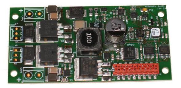
The kickerboard has also been redesigned from scratch and is shown in figure 4. The former design was based on a simple boost converter. The design uses very little board space but has three major drawbacks. Firstly, if the firing IGBTs malfunction or are falsely commanded to switch on for a longer period the main power source is short-circuited. This is also true for the controlling MOSFETs, responsible for the charge process. A short-circuited lithium-polymer battery can easily deliver more than 80A, which effectively destroys the kicker PCB traces. Lastly, the boost converter topology incorporates some severe voltage spikes during switching/charging.
3.2 Kickerboard (continued)
The new design uses the Single-Ended Primary-Inductor Converter (SEPIC) topology [8], which is depicted in figure 5. The capacitor C$^s$ already mitigates problem 1. A malfunctioning firing IGBT can only drain the charged capacitor C${out}$, the main power V${in}$ is no longer shorted. The design also reduces the problems of voltage spikes as the capacitor C$^s$ can partially absorb them. A malfunctioning charge MOSFET Q$^1$ is still a problem. Therefore the supply rail of the kicker circuit is protected by the IPS6021 Intelligent Power High Side Switch [9]. The IPS6021 functions like a resettable fuse. It has a overcurrent shutdown at 31A and a overtemperature protection. Depending on the cooling area the average current can thus be specified. We configured it to approximately 4A. The IPS6021 features an automatic restart after the fault condition has been removed.
![Fig. 5. SEPIC topology used for capacitor charging [8]](/tdps/soccer_smallsize__2014__TIGERs_Mannheim/_page_5_Picture_1.jpeg)
3.2 Kickerboard (final)
The old design had a further issue that in the event of damaged components the charged capacitor voltage (up to 250V) can reach all other components on the robot, causing severe damage to the electronics. The new design uses digital isolators (up to 1kV [10]) to separate mainboard electronics from kicker electronics. The charge and firing controlling ATmega has been removed from the kickerboard, its functionality is now part of the KD microcontroller. The new kickerboard is thus a dumb board. It has an SPI interface to the ADC for current and capacitor voltage reading and three lines for charging and discharging. An additional line serves as error feedback and is pulled high if the capacitor voltage exceeds 190V or a overcurrent situation occurs. The kicker interface thus consists in total of eight lines. The capacitors have been reduced to 2x2000µF with a maximum rated voltage of 200V. We use a nominal charge of 180V for straight and chip kicker. The charge frequency is currently 100kHz, but can be extended to 1MHz. We plan to investigate the different frequencies and duty-cycles for an optimal charging process.
4 Software
During the RoboCup 2013 in Eindhoven we figured out, that our AI has some serious drawbacks in regard to speed and reaction time. A major component of our AI last year was a learning Playfinder. It tried to first analyze the current game situation, then compared this situation with other situations stored in our knowledge-base. Based on past play strategies and their results, the Playfinder chose a set of plays that have been proven to be most likely successful in the given situation. The problem with this approach is that we assume that a play will be selected and fully executed. This behavior does not fit to the reality of a match in the SSL. We had to break with the idea of our play concept and move towards a less hard coded concept, where it is possible to quickly change the strategy.
This is why we decided to restructure our AI to a more agent like AI concept. Main goal of this redesign was to achieve a more fluent game-play, faster reactions and better stability. This means for example, a robot should do a goal kick if it is possible instead of trying to perform its current play that may be selected due to a situation that is already irrelevant.
The performance of our robot control was very poor as well. We were not able to control our robots as precisely as we planned to. With the new robot version, there were several new sensors and a new, more complex firmware. The robot got much more intelligence. It received its position directly from the vision computer and used it to drive along an absolute spline which it received from our central software. The control should have been much more precisely compared to simple velocity commands. It turned out that there were several issues with this concept that primary resulted from insufficient time for testing. For this year, we improved and extended this concept and focused on a stable and precise control.
4.1 Transformation to an agent based AI concept
The current concept of our AI is based on hard coded plays. A play consists of one or more roles and a hard coded plan of how to execute a certain tactic. Most plays will first establish an initial state. An indirect shot play, for example, would send one bot to the ball and one bot to a good position for receiving the ball and kicking it into the goal. During the time the robots need to reach their positions, the game situation could already have changed, so that the indirect shot is not useful anymore. There may be no direct view between the two robots. We even saw situations where the robot near the ball could have performed a goal kick, but tried to pass to the other bot anyway because the play told it to do so.
Detecting such situations and cancel plays would be a solution to this, but this will potentially result in many cancellations while the plays have no time to even prepare their tactic. We decided that our current plays have no future and must be replaced. In the past, we invented different kinds of static tactics. This resulted in many different hard coded implementations that were barely tested. So for the new concept, we also focus on simplicity.
Nearly all plays have been removed and merged into four main plays: the support, offense, defense and the keeper play. These plays are always running and it is not intended to restart or remove those plays during the match. Using these plays made it easier to transform the existing AI. Additionally, grouping bots and their roles into these plays makes it easier to coordinate each group.
Luckily we could reuse a lot of our old code, including ball getting, shooting and defending mechanisms. Each play has only one role type, but it can have multiple roles of the same type. With these changes we gained the possibility to play more ball orientated than in the past. Key mechanic in this design is that we now have only one role dealing with the ball, but this role is always assigned to the robot who has the best chance to do something awesome with the ball. This means we now have a fast switching offense role that is always ball orientated and ready to shoot goals.
There are only four plays now that are more or less static and there is one role for each robot. The number of roles assigned to each play can vary throughout the game. In some game situations it is better to have more defenders and in others it is better to have more supporters. The role-assignment is done by the RoleAssigner module that is also completely new in the AI. It will decide when to switch roles and assign an appropriate number of roles to each play. It is important that the RoleAssigner will always assign the OffenseRole to the robot that can best deal with the ball. Especially if two robots will perform an indirect kick, the receiver must be chosen as soon as the ball is moving towards it.
A key decision that we established during the development of the new AI was to have as many logic as possible in our analysis module Metis. The calculation of, for example, the optimal supporter positions or of possible shoot targets for the OffenseRole should not be done in the role but in Metis. This will simplify the roles and reduce implementation errors. Predictable performance is also an advantage. If Metis will calculate all decisions continuously, that will take more computation than calculating on demand but we can be sure that the time to compute will be approximately constant and this will make our software more robust against performance peaks. Last but not least, the calculated decisions can be visualized all the time, so it is easier to validate the algorithms.
There is no communication between roles except the coordination within the plays. Communication is not necessary as we calculate everything in Metis.
4.2 RoleAssigner
In the new AI concept, assigning bots to roles becomes more important. Since the game strategy can change at any moment, switching bots to different plays according to the game situation in a fast and intelligent manner is essential. Therefore a new RoleAssigner is implemented, trying to save driving distances by appropriate and fast role switching according to some constraints. The Role-Assigner is called on every frame to process the current situation. It assigns the appropriate roles, but not regarding the role as itself, but regarding the play which the role belongs to. The plays then organize the bots they get, so they will not block each other because they shall move to opposite destinations.
To evaluate the current situation and assign the bots intelligently, the Role-Assigner uses some partly simplified mechanics from the corresponding plays, to estimate the behavior of the bots if they would be assigned. Firstly, the best candidate for the offense play is computed. Therefore the RoleAssigner uses an approximation procedure to determine the best spline for each bot to the ball while considering bot's and ball's current movement. The shortest (timely and laterally) spline belongs to the best suited bot for the offense play. This also ensures the selection of the right bot when the ball is moving towards it (i.e. after a pass). Afterwards, the best defense bots are chosen from the remaining assignees. Though the RoleAssigner is able to reduce or increase the number of defenders in specific game situations, usually there will be two defenders. The role assigner then builds a possibility tree from the remaining bots distributed on the desired defense positions, which are already calculated in Metis, and computes the overall score of each limb, where the score is determined by the minimal time the bots will need to reach the positions and the current position of the bots (bots in the back will be preferred to avoid too long driving distances, i.e. if a bot far in a back has to drive on the opposite field side because it is now a supporter). The combination of bots with the best score will be the new defender combination. At least, the remaining bots will be assigned to the support play to assist the other bots or offer themselves for a pass.
Indeed the RoleAssigner calculates the best distribution of bots every frame, but it will wait a while changing the play of a bot when two bots recently already switched plays, to avoid a toggling between those two bots. Hence, the new RoleAssigner fulfills the essential requirements of the new AI concept, however future improvements based on in-game observations will obviously occur.
4.3 Offense
The offense role consists of three states, namely BallGetting, Shooting and Stop. Obviously the BallGetting state tries to achieve ball possession. The main task for this state it to calculate a movement destination for moving balls. The role calculates a destination that the ball and the robot both reach at the same time. Therefore it uses the WorldPredictor module which returns times according to current speeds and the use of the pathplanning module.
After the robot enters an area near the ball (e.g. <500mm) the ShootingState is taking over. The Metis module continuously calculates possible targets which is either a point on the goal line or a team member. The robot is positioning himself behind the ball, on an extended line from the target to the ball. After shooting (or passing) the RoleAssigner determines a new robot for the OffenseRole. In case of a pass, the new robot for the offense role is the pass receiver. Like mentioned above there is only one active OffenseRole but the pass sender and the pass receiver are both controlled by that one OffenseRole. This is possible due to the fast switching assignment performed by the RoleAssigner. The pass receiver that usually has been a SupportRole before and already prepared for a redirect will now aim to the target that was already calculated by the Metis module. It depends on some heuristics whether the target is the goal or another robot.
The OffenseRole uses very simple mechanisms but due to the fast switching assignment, more complex and individual plays can be created automatically. Without any additional coding, great plays like an indirect shot or a doublepass could happen in game and on demand!
4.4 Position estimation for SupportRoles
Since - in case of our team possessing the ball - the two SupportRoles are set to receive passes and become offensive when doing so, the ball as well as the opponents goal should always be visible from the position of the relevant bots. In order to achieve this, a list of possible locations on the field is created as follows: Two sets of rays are created, one having its offsprings distributed equally on the opponent's goal line and ending as well equally distributed on the middle line. The rays of the second set all start in the point the ball lies on and end again equally distributed on the line between the opponent's corners. This is only the case when there are no bots located in the opponents half of the field.
During a usual match situation, any bot can disconnect a ray from its endpoint by interrupting it. Now, the list of possible great SupportRole positions is created by calculating all remaining intersections between each ray of both sets. The optimal position for each SupportRole are found by linear search of the intersection with the least distance to the questionable bot.
The amount of rays n in each set can be scaled arbitrarily; a reasonable value is between 30 and 40. One could wish more rays for bigger fields or less for smaller ones (training/test, typically). Even though the whole process gets repeated around 60 times a second, it does not seem to cause performance issues; most likely because only rather simple operations are required. Last but not least, the calculated positions are always located in the opponents half of the field, creating a fast and offensive game. If the Tigers do not possess the ball, the support-role tries to cover dangerous opponent bots.
4.5 Improved movement policies and local skill system
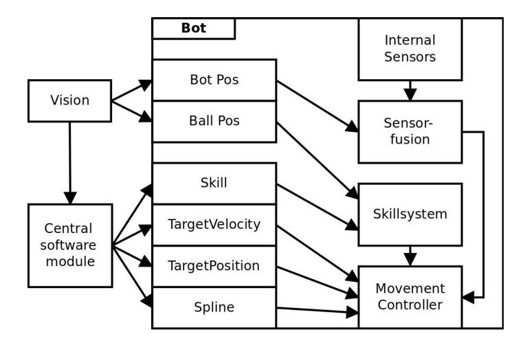
A serious drawback of our team in the year 2013 was an inaccurate and slow robot control due to issues with the wireless connection and the movement controller calibration. The new hardware included new sensors like acceleration and gyroscope in addition to the motor encoders. We also sent the robot positions received from the vision computer directly to each robot. The packages only passed the base-station and not the central software. This results in a smaller delay and the robot can use the position in the sensor fusion to fix long-term errors. The absolute position is used for trajectory control of the splines that are send to the robot by the central software.
This year, we will improve and extent this concept and focus on precise and fast movement control. Figure 6 gives an overview of the new system. There are essentially two extensions to the system from last year. One is the skill system that makes it possible to execute simple tasks directly on the robot without interaction with the central software. This is especially useful for ball interaction, so we will send the ball position to the robot as well. One example for a skill could be a simple keeper that controls the target position depending on the ball position. Another case would be a shooter that could control the speed and angle faster and more precise, before kicking the ball. For the future it is also planned to use a local camera to better detect the ball in front of the robot. This would give the shooter skill even better sensory data and a delay could be avoided compared to sending data to the central software and waiting for new actions.
The second improvement is a variety of control policies that have yet to be tested but could be used in parallel depending on the current situation.
4.5 Improved movement policies and local skill system (continued)
In the last year, we only sent splines to the robots. As the robots knew their positions, they could control their absolute position on the spline. For control, we used a PID-controller for each dimension x, y, ω as well as for position and velocity respectively. We were not satisfied with the performance of those controllers, so now we only use a chained P-Controller for position and velocity for each dimension and additionally control each of the four motors with a PIDcontroller. This has the advantage, that if the motor controllers are performing well, movement controllers other than the spline controller will also perform good.
Using only splines for movement control turned out to be imprecise in certain situations like small movements or simple positioning. That's why we added a positioning controller. As we know the absolute position of our robot, we can simply give the robot a desired target position (that may also change frequently) and the robot will just work on its positioning. First tests showed, that the robot is able to react very precisely and fast. The position controller will preferably also be used by the local skills.
A third movement controller is based on velocity, which is the classical concept that many teams use and that we implemented before using splines. This controller could be used as a fallback, if the other controllers do not perform as expected, but there are currently no plans in using it apart from manually controlling robots.
References
- US Digital. E8P OEM Miniature Optical Kit Encoder, 2012. http://www.usdigital.com/products/e8p
- Nordic Semiconductor. nRF24L01+ Product Specification v1.0, 2008. http://www.nordicsemi.com/eng/Products/2.4GHz-RF/nRF24L01P
- STmicroelectronics. STM32F405xx, STM32F407xx Datasheet, 2012. http://www.st.com/web/catalog/mmc/FM141/SC1169/SS1577/LN1035/PF252144
- STmicroelectronics. STM32F302xx, STM32F303xx Datasheet, June 2013. http://www.st.com/web/catalog/mmc/FM141/SC1169/SS1576/LN1531/PF253449
- R. Marino, P. Tomei, and C.M. Verrelli. Induction Motor Control Design. Advances in Industrial Control. Springer, 2010. 978-1-84996-284-1.
- B. Robyns, B. Francois, P. Degobert, and J.P. Hautier. Vector Control of Induction Machines. Power Systems. Springer, 2012. 978-0-85729-901-7.
- International Rectifier. IRS2336(D), IRS23354(D) High Voltage 3 Phase Gate Driver IC, April 2011. http://www.irf.com/product-info/datasheets/data/irs2336.pdf
- D. Zhang. AN-1484 Designing A SEPIC Converter, April 2013. http://www.ti.com/lit/an/snva168e/snva168e.pdf
- International Rectifier. IPS6021 Intelligent Power High Side Switch, November 2006. http://www.irf.com/product-info/datasheets/data/ips6021pbf.pdf
- Analog Devices. ADuM744x 1kV RMS Quad-Channel Digital Isolators, 2012. http://www.analog.com/static/imported-files/data_sheets/ADuM7440_7441_7442.pdf