2014 Team Description Paper: UBC Thunderbots
Jonathan Fraser, Somik Ghosh, Christopher Head, Sarah Holdjik, Natasha Jaques, Alice Lam, Brian Wang, Andrew Wong, Komancy Yu
The University of British Columbia, 2329 West Mall, Vancouver, BC Canada V6T 1Z4
Abstract This paper details the 2014 design of UBC's Small Size League team robot, to be entered at RoboCup 2014 in Joao Pessoa, Brazil. The main focus of this year was to greatly improve the thermal and computational performance of our electrical hardware and to make our artificial intelligence more comprehensive.
1 INTRODUCTION
UBC Thunderbots is an interdisciplinary team of undergraduate students at the University of British Columbia. Established in 2006, it pursued its first competitive initiative within the Small Size League at RoboCup 2009. The team also competed in RoboCup 2010 – 2013 and is currently seeking qualification for RoboCup 2014. Over the years, it has made significant developments of its team of autonomous soccer playing robots. This paper will outline the progress in implementation of the current model of robots, focusing on the mechanical, electrical and software components with particular emphasis on the digital logic design and the artificial intelligence (AI) plays.
2 MECHANICAL DESIGN
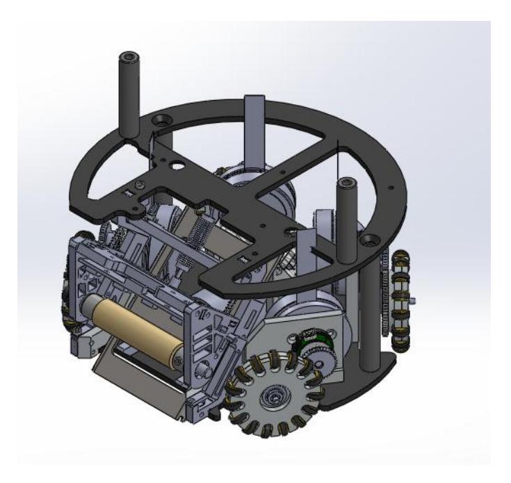
The maximum dimensions for this year's robot can be found in Table 1 below.
The mechanical design of the robot did not undergo any significant changes from the 2013 robots, in order to better facilitate software testing, as well as allow more time to plan for major changes in the following year. The robot is driven by four custom omnidirectional wheels, driven by 30W brushless DC motors. The linear kicking action is achieved using a cylindrical solenoid with a mild steel plunger and attached kicking head. Similarly, the chip-kick action is achieved using a flat solenoid, with a mild steel plunger that actuates a levering plate. The dribbler, which catches and otherwise handles the ball, consists of a rotating shaft with a silicone covering and is driven by a 30W brushless DC motor. For more details on the mechanical function and design of the robot, please refer to our 2013 team description paper [1].
Maximum Robot Dimensions
| Maximum Height | 148 mm |
|---|---|
| Maximum Diameter | 178 mm |
| Maximum Ball Coverage | 18.1% |
3 ELECTRONICS
(This section contains multiple subsections detailed below.)
3.1 Logic/Supervisory
Over a period of time, we have evaluated a large number of options for building CPU cores as part of our FPGA bitstream, thus saving board space and achieving tight integration between firmware and VHDL-implemented peripherals. Unfortunately, our results in this direction have been disappointing. Our initial target was the Navre, an implementation of a classic-core AVR to which peripherals could be attached. While the Navre is solid, the lack of a hardware multiply instruction in the classic core instruction set limited performance. We then considered the pAVR, a pipelined implementation of an enhanced-core AVR. Unfortunately, shortly before RoboCup 2013 it was discovered that the pAVR contains a number of bugs causing improper instruction execution. Our next target was the LEON3, a SPARC CPU originally designed for the European Space Agency. This was reliable, but firmware enhancements revealed performance problems; these were caused firstly by the limited bus bandwidth to SPI Flash memory where code was stored for execute-in-place usage, having grown too large to fit in the FPGA's internal memory, and secondly by the lack of a hardware floating-point unit, one being available but too large to fit in the available FPGA logic resources.
Having found in-FPGA CPUs unsatisfactory, for RoboCup 2014 we are switching to a two-chip solution, with an STM32F4-series ARMv7-M hard processor on the board connected to the FPGA via a high-speed SPI bus. The addition of this hard CPU simultaneously more than doubles CPU clock speed, adds a floating-point unit, massively increases available Flash and RAM, frees up significant logic resources in the FPGA, and provides us with two useful new communication interfaces on the board: a USB engine, whose signalling standards are likely impossible to achieve with an FPGA alone and which would take a lot of time to develop; and a proper (non-SPI) Secure Digital card interface, which is impossible to develop on an FPGA due to the necessary specifications not being published.
The addition of a microcontroller also permits the complete elimination of the external analogue-to-digital converter chip, since the built-in ADC is sufficient. It also permits the elimination of the SPI Flash memory, as the FPGA's configuration bitstream can instead be stored on the Secure Digital card, already present for data logging purposes, and delivered to the FPGA at powerup.
Division of logic between the two devices means that sensors and actuators must be allocated appropriately to the specific device that can best drive them. We elected to control our charger, kicker, and chipper from the microcontroller because they are the most safety critical components of the robot (due to the potential for overcharging) and doing so minimizes the number of components in the pathway from ADC to output. All analogue signals were allocated to the microcontroller, lacking any other choice. Accordingly, digital signals directly related to analogue signals, such as drive levels for the optical ball-sensing devices, were also allocated to the microcontroller. As already mentioned, USB and Secure Digital interfaces were also allocated to the microcontroller. Hall sensor reading and motor driving remained allocated to the FPGA, as the parallelism it offers is ideal for operating the 15 inputs and 30 outputs respectively. Our new gyroscope and accelerometer were also attached to the FPGA, allowing them to be placed on dedicated SPI buses rather than sharing bandwidth with other devices. The MRF24J40 radio was also attached to the FPGA, an unorthodox choice made because its SPI protocol involves large numbers of small bus transactions which would otherwise consume a lot of CPU time on the microcontroller; the FPGA thus acts as a protocol offload engine. Finally, the optical encoders were attached to both the microcontroller and the FPGA; this was done because the microcontroller provides hardware support for quadrature encoders, but we were at the time of writing investigating noise problems which might, conceivably, have made the peripheral unsuitable and necessitated the construction of more advanced filtering circuits, which could be implemented easily in the FPGA.
3.2 Firmware
The provision of the much more powerful STM32F4 ARMv7-M microcontroller allowed us to reconsider the architecture of our firmware. In prior years, our firmware was implemented as a main loop polling for work. This year, we decided to instead use a real-time OS. We chose FreeRTOS, due to it being large enough to provide a reasonable set of primitives, but not too large nor too intrusive into our desired architecture.
FreeRTOS has three targets, or "ports", available that would work acceptably for the STM32F4 with the GCC compiler. However, all of these ports have specific drawbacks: the CM4F port does not use the memory protection unit, which is useful for catching stray pointer dereferences and stack overflows; the CM3-MPU port does not handle saving and restoring floating-point context between tasks and its memory protection is overly strong, forcing globals to be assigned to specific tasks via ELF sections, treating tasks more like processes than threads, and requiring undesirable effort to fully specify allowed memory areas for each task; and finally, the CM3 port neither uses the memory protection unit nor context-switches the floating point registers. As such, we chose to write our own FreeRTOS port, which handles the floating point unit and also enabled the memory protection unit only in such a way as to catch the most common errors with minimal effort.
Because the STM32F4 is the same microcontroller we use on our radio base station, we also ported our radio base station code to use FreeRTOS. This served as a solid test of the FreeRTOS port and other common code before starting work on the new robot hardware.
3.3 Sensors and Control
Previous years' designs have seen incremental updates to the control algorithms on board the robot. Moving away from simple PID towards acceleration based (Bang Bang) control has yielded vast improvements in precision and speed. All methods, however, are limited by the ability of the on board firmware to identify its location and system state relative to the desired destination.
Current iterations of the system use wheel speed encoders as the only real-time feedback, with updates provided by the vision system at a much slower interval. These updates are compensated at the control computer level for vision system lag and are therefore subject to model mismatch issues at higher speeds. Additionally, the only real-time feedback (encoders) are subject to the particularly insidious issue of wheel slip.
To improve upon the this situation and overcome the aforementioned deficiencies, this iteration of electronics will include both an accelerometer and gyroscope. These two instruments, while subject to their own shortcomings, can compensate for both wheel slip and model mismatch of the AI status updates when travelling at high speed. These two devices will be integrated with the wheel encoders to produce a more accurate state predictions and by extension more precise control of the robot.
3.4 Motor Driver
As previously mentioned, we are taking the opportunity of redesigning the circuit to address the heating problem caused by the integrated motor driver chip, L6234, used in the last design. Since large on resistance proves to be a common issue in integrated motor driving solutions, after extensive research, w e are going with discrete half bridge drivers and MOSFET half bridges in this design iteration. We found three half bridge drivers and three MOSFET half bridges per motor a reasonable midpoint solution to reducing inline resistance with the motor phase and the constraint of available board space.
We have yet to test this driving scheme in the new iteration of circuit board. The inline resistance is expected to be reduced by a factor of 10 and this specification alone would allow our robot to drive for a long time and to accelerate or decelerate harder without overheating.
4 SOFTWARE
(This section contains multiple subsections detailed below.)
4.1 Skills Tactics Plays
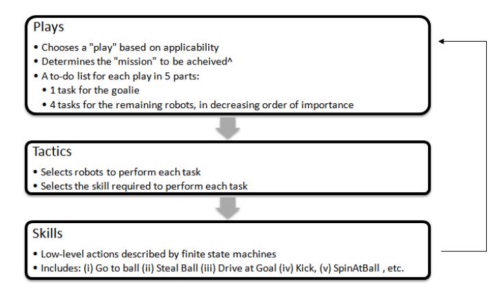
The high level decision making model used is the STP model, developed by CM-Dragons in 2003 [6]. This hierarchical model breaks the high level decision making into three main abstractions: Skills, Tactics and Plays.
Skills are composed of low level actions for an individual robot such as movement, kicking or dribbling the ball. Tactics take in various world invariants and calculations and then determine when to use such actions. Plays are dynamic role assignments for each robot to carry out tactics in cohesion based upon the current world invariants and playtype. Choosing the correct invariants ensures that an effective play gets chosen for the scenario on the field.
Loose Ball Play Type This year a new invariant has been added to the AI for off ball playtype. In previous years the ball was either in possession of a friendly team or an enemy team. This year a third invariant has been added for when neither team has the ball in its possession. This adds a new category to our plays and allows us to take advantage of a myriad of tactics in recovering the ball or hindering the enemy. Dealing with a loose ball effectively is very important to the overall strategy. It presents an opportunity to challenge the other team and press for the ball.
Play Books Play books were added to allow different plays to be selected for different matches at runtime. This allows our team to create a custom sets of plays for each opponent we face. Having play books allow us to easily and quickly customize a set of tactics to focus on so that we can capitalize on any weaknesses in our opponent's offense or defense.
Offense Further improvements to the Triangle Offense from last year were made in order to better facilitate the positions and roles of the two off-ball offenders. Off-ball robots now position themselves to be able to one-touch shoot into the goal.
Defense Our tried and tested defense has largely remained the same from previous years. Two defenders assist the goalie by blocking all possible paths for the ball to reach the goal. This is executed by drawing two vectors from the ball to both friendly goal posts and positioning the goalie and two defender robots to fill out the triangle. This year due to the addition of the off-ball invariant we can allocate the other three robots to also take on passive defensive roles. The three robots that are not defending the goals now position themselves to block passes of enemy offenders.
4.2 Navigator
Our team employs the Rapidly Exploring Random Tree for finding navigation paths to a destination. In past years, only the next intermediate point to the destination would be calculated by the navigation layer each software tick. The Navigator now correctly calculates a complete path with set timestamps to the destination, and then keeps to that path with varied hysteresis, unless field invariants force a path change. In addition, a new flag was added for indirect and direct kicks. This allows the navigator to use more precise and careful navigation with respect to the ball in order to correctly line up for kicks.
4.3 Kalman and Ball Filters
With any data received from sensors it is to be expected that there is some noise which prevents the recipient from receiving precise and accurate results. One method to eliminate noise is the Kalman filter, which attempts to smooth out any noise in a system by using measurements from a sensor, previously estimated locations, and control inputs into the system to provide an estimate for the current state of a system. Our AI has made use of a Kalman filter for many years with success. Recently, we have noticed that work could be done to improve the Kalman filter. Some improvements being considered this year are improvements to the interpretation of control inputs and adjusting how much the calculated versus measured input are trusted. In order for the filter to accurately predict changes to the system it is required that the filter knows of any inputs into the system. In this case the system is the robot and the filter must know of any accelerations applied to the robot. Ensuring that the filter has the most accurate values for the control input will ensure that the filter is able to more accurately predict the state of the system. A nice feature of the Kalman filter is there is some customizability with how the final result is created. More emphasis can be placed on the calculated versus the measured value. Fine tuning this balance will generate accurate predictions.
Our AI also has a ball filter. This filter, given a set of possible objects that are the ball and a confidence percentage based on the shape of the object, determines which is the ball. Improvements were made to this filter as previously problems were noticed with ball detection. Being able to know where the ball is at all times is very critical to success.
5 Acknowledgements
We'd like to thank the Faculty of Applied Science; the departments of Mechanical Engineering, Mining Engineering, Electrical Engineering, Engineering Physics, and Computer Science; and the University of British Columbia for their continued support. We'd also like to thank all our sponsors for their generous contributions to undergraduate student learning and research.
References
- Palmer, A., Head, C., Lai, M., Poon, H., Lin, T., Wong, A., Wang, B., Fraser, J., Yu, K., 2013 Team Description Paper: UBC Thunderbots, 2013
- Palmer, A., Balanko, J., Head, C., Fraser, J., Lum, S., Parizeau, M., Poon, H., Lin, T. 2012 Team Description Paper: UBC Thunderbots, 2012
- Palmer, A., Jiwa, A., Huynh, S., Head, C., Fraser, J., Leson, A., Knoll, B., Suyadi, S. 2011 Team Description Paper: UBC Thunderbots, 2011.
- Jiwa, A., Knoll, B., Head, C., Hu, H., Fraser, J., Serion, J., Baillie, K., Lam, LT. 2010 Team Description Paper: UBC Thunderbots, 2010.
- Browning, B., Bruce, J., Bowling, M., Veloso, M. STP: Skills, tactics and plays for multirobot control in adversarial environments, 2004.
- Browning, B., Bruce, J., Bowling, M., Veloso, M. CMDragons03 Team Description Paper, 2003.