Team ACES, Pakistan (Team Cooperative and Strategy Planning Robots)
Muhammad Mobeen Younis, Muhammad Hassan Khan Niazi, Muhammad Mohsin Khan Niazi, Aneeq ur Rehman, Humayoon Gondal, Jawad Saleem, Anza Aqeel Ahmad, Ali Afzal, Wajih Khan, Hammad Shahid Khan, Zain ul Hassan, Dr. Shoab Ahmad Khan, Ali Syed
Center for Advanced Studies in Engineering, Islamabad, Pakistan; Department of Electrical and Computer Engineering
Abstract This paper describes the mechanical, electrical and software designs of the Team ACES intending to participate in RoboCup 2015 in Hefei China. This year team focused on the improvement of communication channels, wireless modules, precise motion planning and accurate locomotion techniques. Encoders are embedded to improve the movement in terms of precision and accuracy. Control mechanisms have also been improved to remove delays in communication and fleet movement. In order to handle the runtime variations of the game state of the art AI algorithms have been introduced this year.
Introduction
Robocup is an international event intended to promote robotics and artificial intelligence. This year we, Team ACES participating in small size league, worked on following domains to improve our last year's fleet of robots. We made major changes in our electrical and software domains with minor changes in our mechanical structure. In this paper we have included simulations to help new teams understand and reproduce our work.
Robot Specifications
The table below presents the key specifications of the Team ACES robots.
Specifications of Robot
| Robot Diameter | 175 mm | | Robot Height | 150 mm | | Ball Coverage | 18 % | | Maximum Velocity | 2 m/s | | Maximum kick speed | 7.5 m/s | | Maximum chip kick distance | 4.0 m |
Electrical System
We have improved our complete electrical system which includes redesigning of communication modules by integrating nRF905 [1] instead of Xbees[2], Kick Chip circuitry and sensors.
Current Electrical Architecture
Below is the complete description of our electrical system.
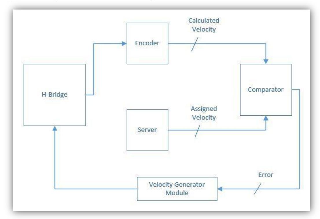
Following is a block diagram demonstration of our complete motion drive control.
Motor Drives
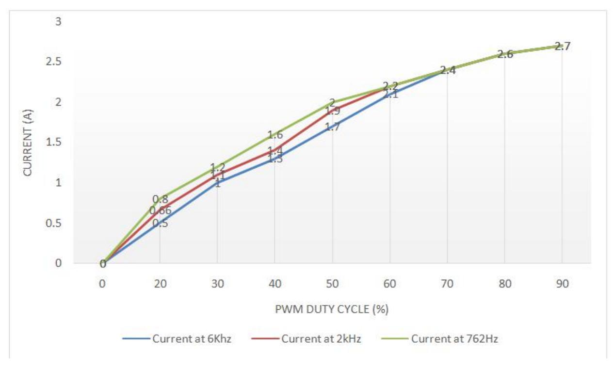
Although we are using the same Motor driver ICs i.e. L298 [3] as in previous RoboCup 2014, but this time we have changed the PWM frequency from 6Khz to 762Hz to get a more linear response between the current and PWM duty cycle. The graph shows higher current value for a given duty cycle at 762 Hz then previously adopted 6 KHz. Hence higher current gives a greater torque.
Central Processing Unit
For the central processing, we are using "Embedded Micro MOJO [4]". MOJO is also mounted on the central mother board. Mojo includes a Spartan 6 XC6SLX9 FPGA. The board has a total of 84 digital IO pins out of which 8 are analog inputs. We have 8 general purpose LEDs. There is an on board voltage regulator that can handle 4.8V - 12V of input. A microcontroller (ATmega32U4) used for configuring the FPGA, USB communications, and reading the analog pins. The Arduino compatible boot loader allows to easily program the microcontroller also it has board flash memory to store the FPGA configuration file. We write our code in Xilinx and flash the code using a tool called "Mojo Loader". In contrast to that there is also an IDE available by Mojo to code the device. This time we have also integrated our new wireless module [1] with this central unit. The main purpose of choosing this device was that it's a small size development board of Spartan 6 and we can easily install and remove the board from our robot. Unlike some other teams whose main controller is embedded on their mainboard we wanted our controller to be replaceable. That's the very same approach we opted for our motor driver.
Previous Electrical Problems & Solutions
Keeping in mind many problems faced in the Robocup 2014 in Brazil, we have improved our electrical architecture to a great extent. Major changes are described as follows.
NRF905 Wireless Transceiver Module
NRF905 is a wireless communication module. Previously we were using XBees. Due to wireless band choking and low transmission power issues faced in RoboCup 2014, we have decided to shift to this module for our wireless communication between team server and robots.
![Image of NRF905 Wireless Module [1].](/tdps/soccer_smallsize__2015__ACES/_page_3_Picture_0.jpeg)
Encoders feedback and Motion Control
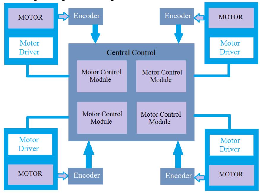
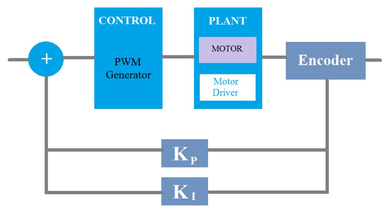
In our system, we have a central FPGA based control unit, it is responsible for controlling PWMs of all four motors. Detailed diagram is given in the figure below.
Kicker Redesign
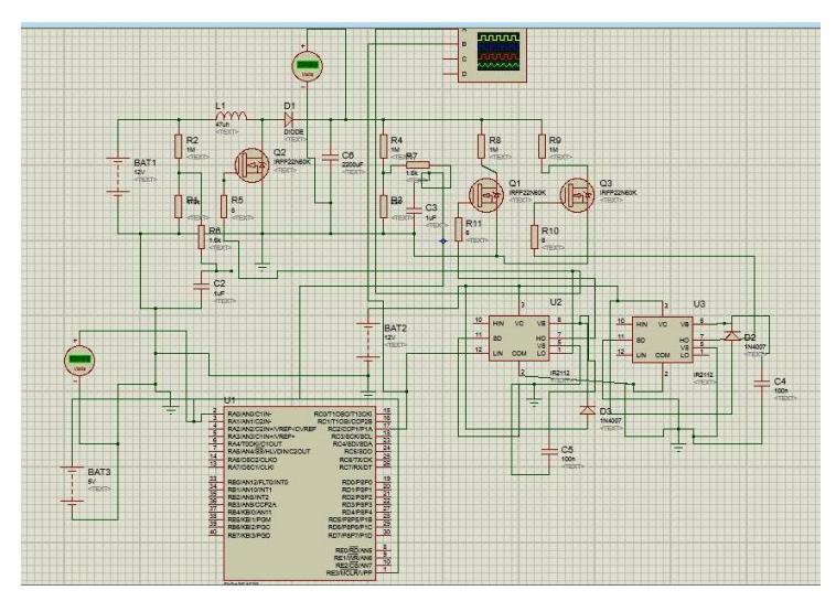
Kicker circuit was redesigned with an on board microcontroller. We used PIC16F microcontroller for the purpose. We are using this microcontroller for monitoring the capacitive boost circuit charging levels and also to monitor the battery voltages and temperatures of the Kicker circuitry which includes inductive components.
Schematic Design: We have used PIC Microcontroller PIC18F4520 [6] for simulation purposes. A snapshot of the simulation schematic diagram is shown below:
Mechanical System
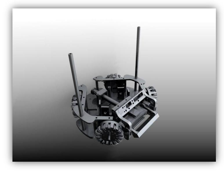
Being a new team and keeping under consideration, the issues and problems faced in the matches of Robocup 2014 in Brazil, we have made significant changes to our mechanical design and implemented different approaches to enhance our performance regarding system control, feedback, and motion control.
Following figure shows the 3D Design of Wheel assembly and chasses.
New Mechanical additions
Previously in 2014, we were varying the pwm at different motors but were unable to acquire any feedback due to the absence of encoders. The only feedback was the SSL vision. This has been a drawback and we were unable to maintain robot performances on different battery levels. In order to overcome this issue, optical encoders have been installed on every motor which let us acquire useful feedback and hence enable us to apply robust feedback control algorithms for velocity profiling and pwm error control. We are using E4P OEM Miniature Optical Kit Encoder [7].
Previous Mechanical Problems & Solutions
Robocup 2014 was the first time we participated in the oldest league of the event hence due to lack of experience our robot fleet faced severe damages to mechanical parts and electrical. This time we have improved our mechanical structure to bear the impacts casted down during accidental collisions and ball strikes. We have also focused on the jerk handling required during the missed shots of the kicker. This time we have applied techniques to absorb down the energy produced by the kicker in missed shots.
Main circuit board connector
In our design, complete electronic circuitry is mounted just above the Drive Plate. This electronic circuitry is composed of the main mother board with onboard motor drivers and central controller. Last time in Robocup 2014, one design flaw which was hindering our performance was the unstable mounting of electronic boards. This time we have properly mounted this circuitry with the jerk absorbing rubber washers.
Jerk absorbers for kicker jerks
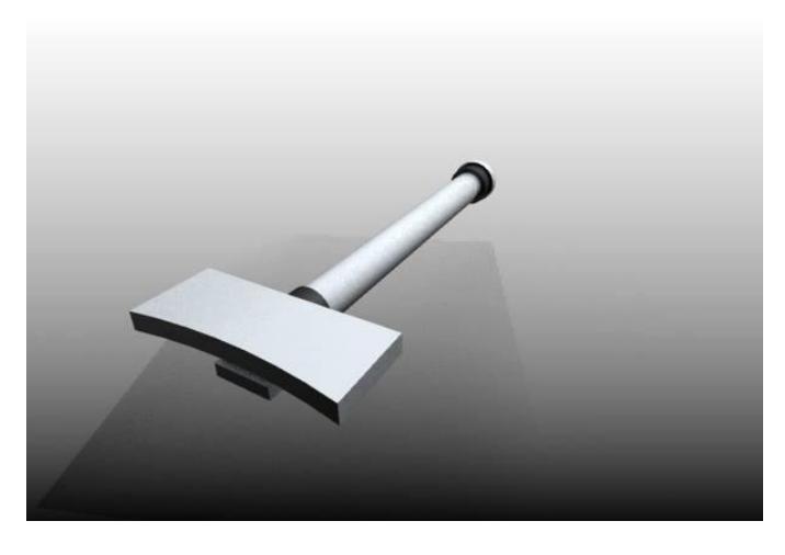
Another mechanical improvement was the implementation of Surplus Kicker energy absorber mechanism. When a kicker shot is missed, a lot is energy is to be absorbed by the chassis of the robot. We have also installed thick rubber jerk compensators for absorbing sudden jerks.
Software
Improving our software schema, we have replaced our previously used hardcoded game plays. During RoboCup 2014, we were using hard coded game play strategies. We used to analyze the game first and then start our most relevant strategy. But we realized that in this way we cannot achieve any good results because when we reach some possible attacking point, the overall game scenario is already changed.
This time we have improved our motion control techniques, Path planning techniques and Main Game Control engine. Detailed Information is as below:
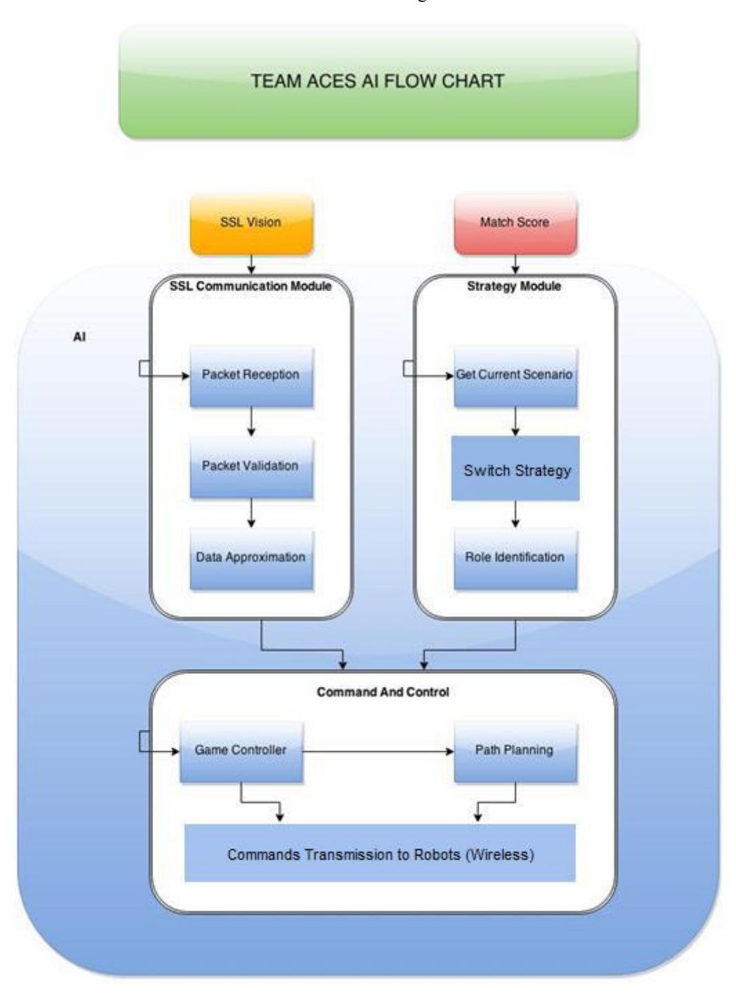
Game Control engine
The flow chart below best describes the structure of our Game Control engine.
Improved Motion Control
Previously we were using simple equations of lines to move the robots in one particular direction. This time we have implemented Omni Drive Equations.
Previously we used to send individual commands like FORWARD, BACK, LEFT, RIGHT, and ROTATIONS. This technique takes a lot of time to follow a particular path and does not provide sufficient efficiency. Now after analyzing our path from current point to the destination point, we continually send velocities to robot for every wheel. In this way we are able to move our robots precisely and smoothly and in marked less time interval.
Path Planning
Previously in Robocup 2014, we were not using any particular technique for path planning. For robust path planning, we have implemented RRT ( Rapidly exploring Random TreeAlgorithm).To reduce the planning delays we have implemented many custom path smoothing techniques. After RRT, we have also implemented RRT * (RRT Star) which has helped us a lot to reduce the processing delay.
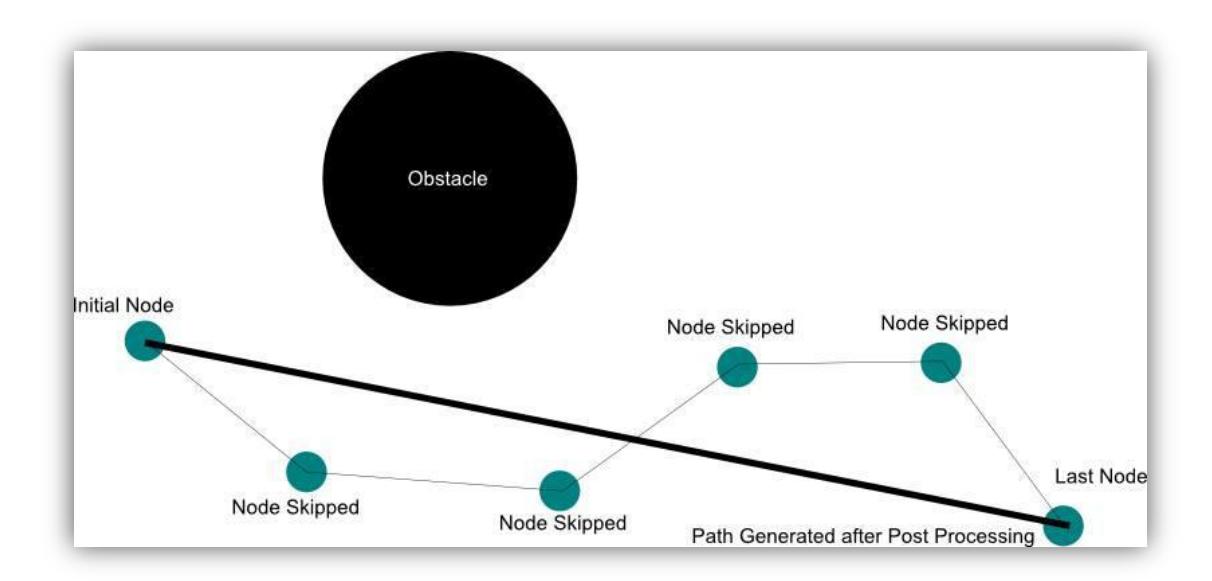
We are also preprocessing the whole field reducing and scaling our field instead of checking and processing on every valid point on the field. We have used "NODE SKIPPING" to smooth the path during obstacle avoidance; we are actually using this technique by populating a set of points from robot to its target. Then checking the direct path condition on every node, we keep on skipping the previous node if next node makes a direct link to the source robot. A small illustration of our concept is shown below.
References
[1] nRF905 Wireless Module, Link: http://www.electrodragon.com/w/index.php?title=NRF905_Transceiver_433MHz-Wireless_Module [2] XBee: (A communication module), Link: http://www.digi.com/xbee/ [3] Motor Driver Full Bridge L298 IC. Link: http://www.st.com/web/en/catalog/sense_power/FM142/CL851/SC1790/SS1555/PF63147 [4] Embedded Micro MOJO. Link: https://embeddedmicro.com/products/mojo-v3.html [5] Arduino NANO Development board. Link: http://arduino.cc/en/Main/arduinoBoardNano [6] PIC Microcontroller, PIC18F4520. Link: http://www.microchip.com/wwwproducts/Devices.aspx?dDocName=en010297 [7] E4P OEM Miniature Optical Kit Encoder. Link: http://usdigital.com/products/encoders/incremental/rotary/kit/E4P