Anorak Team Description Paper
Hamza Munir, Aamir Sheikh
Anorak Artificial Intelligence and Controls, Center for Advanced Studies in Engineering, Islamabad, Pakistan
www.athode.com/anorak · http://arduino.cc/en/Main/ArduinoBoardMega2560 · http://www.nordicsemi.com/eng/Products/2.4GHz-RF/nRF24L01 · http://www.st.com/web/en/catalog/sense_power/FM142/CL851/SC1790/SS1555/PF63147
Abstract This paper describes the hardware and software that will be employed by the Anorak team for the upcoming RoboCup 2015, F180 category. We are implementing a modular AI approach with focus on agent awareness and spontaneous real-time decision algorithms. In hardware, Anorak's efforts in low cost, high reliability machines has led us to introduce cast acrylic as an alternative structural material for robot bases and mounts. Our drastic redesign will make it possible for teams to operate on lower budgets, thus making it possible for more teams with valuable ideas in AI to participate. Keeping in mind that many regions globally do not have access to, or cannot afford, AI solutions; we are interested in developing alternative approaches to the field in order to reduce costs and overcome availability of components in such regions.
1 Introduction
Anorak was formed in 2014 with the aim of developing connected AI systems. Our team focuses on building connected teams of autonomous AI which work together on a team based task. We are working on making systems such that individual members of a team are "aware" of the circumstances the team is working under collectively. This includes acknowledging the deficiencies of underperforming members (due to technical faults and such), and taking appropriate measures to reduce the gaps in team performance caused by them. This involves modifying strategy and/or reprioritizing team objectives.
Parallel to our research objective in artificial intelligence, Anorak builds robotic machines that are low cost, reliable and easily serviceable.
Anorak comprises of electronic engineering students and hardware technicians.
2 Team Targets
The current RoboCup 2015 F180 tournament will be the first time Anorak is participating in a RoboCup event. Our targets for the tournament are successful completion of performance expectations from our AI approach and from our hardware. In this respect, the hardware serves only has a reliable vehicle for our AI algorithms. We are currently using a generic hardware design used by most teams at the RoboCup F180 matches. Without any particular design evaluations, our main target for hardware is to have it low cost and yet reliable for the duration of the tournament. We are aiming at having hardware maintenance for each robot that remains below 20% of the unit cost. Our current aim is at keeping unit costs below US $120 per robot.
To evaluate software performance, we will be logging game data of our matches on our server and evaluating success rates of each component of our software. This includes targets such as having collision rates below 15% in all instances where collisions were possible, shoot on target rate of 67% weighted against hardware shortcomings and having no more than 30% of zone allocation errors. Zone allocation is explained in the software section later on.
3 Hardware
This section describes the hardware design and electronic components used by the Anorak robots.
3.1 Mechanical Design
Our targets for the mechanical hardware are shown in Table 1.
Table 1. Mechanical Targets
| Max Mass | 2.5 kg |
|---|---|
| Dimensions | Dia: 178 cm; Height 145 cm |
| Centre of Gravity | Through central axis, less than 80mm above ground |
| Max velocity | 4 m/s |
| Max Angular velocity | 2 rps |
| Acceleration | 6 m/s² |
| Ball coverage | 16% |
Our current prototype has a mass of 2.3 kg and can be enclosed in a cylinder of diameter 176mm and height 145mm.
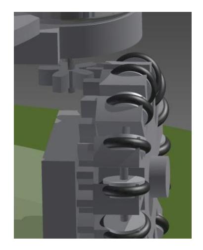
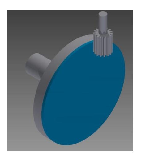
The robot registers straight line speeds of about 2.5m/s with an acceleration of 2m/s². This is mainly down to the power transfer mechanism we are currently using. This issue, and our solution, is elaborated in detail under the section "Power Transfer".
3.1.1 Low Cost Strategies
Our goal of developing low cost, high reliability robots involved detailed research in suitable materials for mechanical structures. We have found cast acrylic to be a competent alternative to 6065 aluminium, leading to significant cost and weight reductions.
Table 2. Cost Comparison for Materials
| 6065 Aluminium | Cast Acrylic Sheet | |
|---|---|---|
| Density | 2.72g/cm³ | 1.18g/cm³ |
| Price per sq ft, 0.6mm thickness | $3 | $3 |
| Fabrication cost per robot* | $250 - $300 | $14 - $25 |
*specific to the team's country of origin
The weight savings gained by using acrylic allows us to raise weight limits in components elsewhere, such as in the use of larger brushed DC motors. This reduces motor costs by over 24 times leading to massive cuts in per unit cost. However, the larger motors take more space, leaving less room for electronics and ball handling mechanisms.
Table 3. Motor Comparison
| Maxon EC45 Flat | Johnson 550 | |
|---|---|---|
| Cost per unit | $85.79 | $3.50 |
| Power | 30 W | 24 W |
| Torque (Peak Eff) | 55 mNm | 62.4 mNm |
| No load rpm | 4370 | 19300 |
| Weight | Acceleration | 218 g |
A principle strategy in reducing cost is to iterate our systems through numerous design modifications in order to make use of components that are easily available in the market. Not only does this lower expenses, but also serves has a challenging technical exercise. On the side, it also means our systems become easier to maintain because the components are easily available in sufficient quantities.
We will be able to provide a comprehensive parts list, along with performance analysis, once we have the final revisions of our systems in June.
3.1.2 Mechanical Components and Descriptions
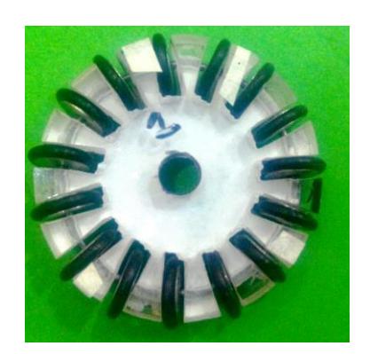
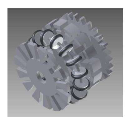
Wheels: We have opted for the traditional design for omni wheels used by most teams on the F180 category. The wheels are made from 8mm cast acrylic. Each wheel has a 45mm milled hub that houses fifteen rubber lined rollers. Each roller has a diameter of 10mm and are mounted on a thin circular steel ring that fits into a machined groove on the hub. An aluminium cover plate is then screwed on and holds the ring and rollers in place.
3.2 Electronic Components and Description
Main Processing Unit: For the main processing unit, each robot has an Arduino Mega 2560 R3 board. The board provides 54 digial I/O pins, 16 analog inputs and 4 hardware serial ports. The processor has a clock speed of 16 MHz.
Communication Module: We have opted for a 2.4GHz radio transceiver which uses the nRF24L01 IC from Nordic Semiconductors. The choice was made because of the quick switching speed between transmission and receiving modes, allowing us to set up a two-way communication system with the robots. The chip also offers better transfer rates and extremely low errors. As compared to other modules, the low cost of the nRF24L01 chip makes it easier for us to keep costs low.
Motor Drivers: Each motor is driven by a L298N dual full-bridge driver by STMicroelectronics. The four ICs are mounted together with a cooling fan. This allows us to operate the motors at higher currents for longer periods of time. Each motor driver receives PWM signals from the main CPU. The CPU manages feedback control via a PID implementation.
Wheel Encoders: Each wheel axle has a slotted spinner. A mounted slot sensor detects the slots and sends input signals to the CPU via a signal amplifier. The count signals are used to determine the rpm of the wheels and is used for PID control of the motors. We are in the process of designing more accurate encoders using a hall sensor IC.
Kicking Circuit: The kicking circuit uses a capacitor bank of 4400µF which is charged using a booster circuit. The CPU controls the discharge trigger through a transistor circuit. Charging takes around 2 to 3 seconds depending on configuration.
Dribbler: The dribbling motor is controlled by a L298N chip which is fed PWM signals from the CPU.
Power Supply: A 3 Cell 3200mAh Lithium Polymer battery bank supplies the motor circuits and the booster circuit for the kicker. A separate power source with two 9V batteries is used to power the main CPU, slot sensors, radio module and IR sensor for the ball. The main battery gives around 30 minutes of play time per charge.
4 Software
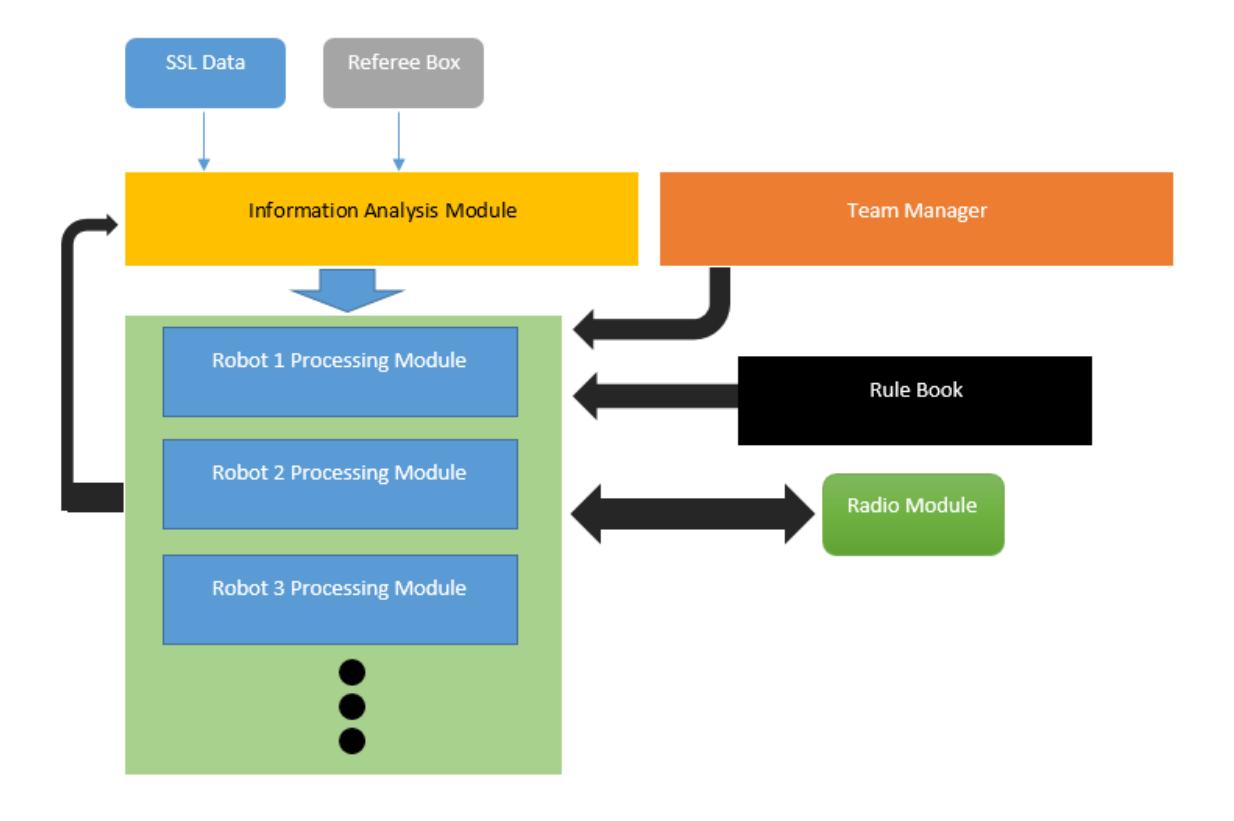
The high level architecture of our software is illustrated below.
4.1 Information Analysis Module
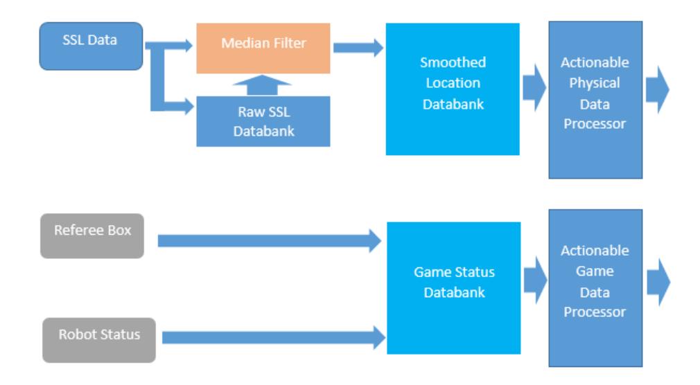
The Information Analysis Module is responsible for preparing actionable data for the Robot Processing Modules. It receives location data from the SSL Vision setup and game status from the Referee Box input. In addition, the module receives robot status information from each Robot Processing Module.
Data from the SSL Vision system is received via UDP, decoded using protobuf and then processed through a simple median filter (T. Huang, 1979, Vol 27). We have been working on implementing a better filtering technique, based on the Kalman method. As soon as our testing is successful, we will be updating the code for the filtering stage. Once filtered, the data is passed to a linked list. The Actionable Physical Data module then processes the smoothed location data to calculate primary information including position, orientation, velocity and acceleration of each game agent. This information is then accessed by the Robot Processing Modules to use as input data for their decision algorithms.
The Information Analysis Module also forwards information from the Referee Box and robot statuses so each playing robot can behave according to the game state.
4.2 Team Manager Module
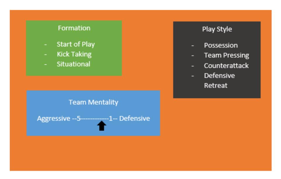
Like in any real game of football, the overall strategy and style of play is determined beforehand by the team manager. Our module mimics the real world role of the team manager. The module contains a range of match and strategy variables that can be edited prior to a match. Through the several previous team description papers that we studied, almost all teams have a predetermined playbook. The concept of a playbook is analogous to our Team Manager Module. However, they differ in that the Team Manager Module does not contain hardcoded plays. What it does is defines the team formation and responsibilities of each member prior to kick-off. It also dictates the team mentality that the players are to display during each assumed situation during the match. Team mentality dictates the aggressive or defensive behaviour a robot demonstrates during the game. An aggressive behaviour will soften decision constraints during passes and shooting. This means that in an aggressive setting, a robot will attempt a shoot even if there is greater probability of not scoring.
Additional to overall strategy, the Team Manager also sets pre-defined formation setups for free-kicks and throw-ins depending on the location where each is awarded.
In our current implementation, configuration of the Team Manager does not change during a match and is only pre-programmed before the start.
4.3 Robot Processing Module
We have approached the AI problem of autonomously playing a game of football in a modular manner. This means that the game is not controlled by one central decision module, but consists of separate autonomous modules that process decisions based on situational data. Central to our AI design is the Robot Processing Module. The Robot Processing Module contains a master algorithm that defines how a player should behave on the football field. The behaviour is governed by situational data. Each behaviour is triggered by a set of situational stimulus and is executed through its respective algorithm chain.
The Team Manager defines the overall strategy. As a blunt example, a statement in the strategy could be to switch to ultra-defensive mode after taking a lead of one goal against the opponent. The manner in which each player conducts their game is determined solely by their respective Robot Processing Module.
At the server side, a separate dedicated instance of the Robot Processing Module is run for each player on the field. The module receives actionable physical information, game state and status of other robots from the Information Analysis module. At each change in game state, the Robot Processing Module of each robot refers to the Team Manager configuration to determine any changes in formation, mentality and play style. It then updates the values of these variables accordingly.
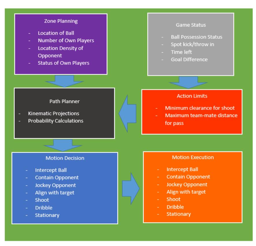
The figure below illustrates the structure and components of the Robot Processing Module.
4.3.1 Zone Planning
Each robot views the playing field as zones of responsibility. The size of each zone of responsibility varies depending on player roles. Attacking members of the team have larger zones of responsibility as there is less risk of conceding a goal at the far end of the field. Because preventing the opponent from scoring has a higher priority, the zones at the defending side are smaller and thus need more members to fill them as compared to attacking.
Additionally, zone sizes for underperforming members (as in case of low battery) will be lowered by the weightage coefficients generated by the robot status portion of the Information Analysis Module.
Each zone has a risk rating. The risk rating of the zone determines how many members of the team it needs. If the risk rating of a zone is greater than another zone, the member of the lower risk zone will leave its position and arrive at the high risk zone to assist the member there. This decision of course involves interzone distances. Members of adjacent zones to the high risk zone have higher priority to join the high risk zone.
Zone risk is a function of ball location and density of opponent members in that location. Currently risk zones are mapped as isosceles triangle patches with the ball as the far vertex and the sides of the triangle proportional to distance of the closest opponent member to the ball.
4.3.2 Game Status
The game status sub module raises direct flags to the motion decision sub module in event of spot kicks, throw-ins and game stoppage. Secondly, it sends weighting coefficient values to the Action Limits sub module. These coefficients relaxes or tightens clearance values for each motion action and essentially determines the amount of risk the robot takes while shooting, passing or following a dribble path.
4.3.3 Motion Decision
The motion decision sub module is the main decision tree used by the Robot Processing Module to determine the course of action the robot will take. The decision tree consists of dynamically ranked statements. The Path Planner sub module conducts kinematic projections and probability calculations to determine whether a decision will yield success. For example, for the shoot decision, the sub module conducts a linear sweep operation to determine the success rate of each shoot path to the target and returns the orientation and shoot speed for the path with the highest success rate.
4.3.4 Motion Execution
Once the highest ranked motion decision has been selected, the motion execution sub module resolves the corresponding vectors according to precoded algorithms and prepares time-coded dispatch packets containing PWM data for each motor (including the dribbler), and discharge trigger value for the kicker and chipper. The data is transmitted to the robot's channel as serial commands in the order of the time-code and is received and executed by the robot's Main Processing Unit.
Creating time-coded packets for future commands of a motion plan at the server side, and then transmitting them in real-time, is part of our development of an Execution Monitor Module and a parallel Contingency Planning Module. The objective of the former is to observe the planned motion against the realworld motion of the robot and provide information on success rate of the planned motion as events unfold. Meanwhile, with the primary planned motion already prepared, the Contingency Planning Module processes an alternative motion plan ready to be used should the Execution Monitor indicate the initial plan's failure. However, these modules are in very early stages and not our focus for the current tournament. We have made our code comply with the requirements of these modules in future to make integration easier.
5 Concluding Statements
The AI approach described in this paper is currently under development. The current version of the software is not a unified version as different modules and their various segments are worked on and tested as required individually and/or with temporary integration. With each week of testing, algorithms need to be reworked, resulting in frequent revisions and often changes in the way we measure the performance of our code. Because of this volatile nature of our AI modules and the tedious nature of tuning for real-world variables, we cannot provide useful performance metrics and conclusions of our modules at the moment. Over the coming weeks as the AI starts taking its final shape and we have sufficiently applied it to our robots with consistent results, we will be able to provide reliable results and outcomes, and share it with the community.
References
- T. Huang, G. Y. (1979, Vol 27). A fast two-dimensional median filtering algorithm. IEEE Trans. Acoust., Speech, Signal Processing, pp. 13-18.
- Cauchy, Augustin (1847). Méthode générale pour la résolution des systèmes d'équations simultanées. pp. 536–538.
- Mordecai Avriel (2003). Nonlinear Programming: Analysis and Methods. Dover Publishing.
- Arduino Electronics Prototyping Boards: http://arduino.cc/en/Main/ArduinoBoardMega2560
- Ross, I. M. A Primer on Pontryagin's Principle in Optimal Control, Collegiate Publishers, San Francisco, 2009.
- Ohlmeyer, E.J., Phillips, C.A., Generalized Vector Explicit Guidance Journal of Guidance, Control, and Dynamics 2006; 0731-5090 vol.29 no.2 (261-268)
- Survey of Numerical Methods for Trajectory Optimization;John T. Betts Journal of Guidance, Control, and Dynamics 1998;0731-5090 vol.21 no.2 (193-207)
- Kalman, R. E. (1960). "A New Approach to Linear Filtering and Prediction Problems". Journal of Basic Engineering 82 (1): 35–45.
- Wan, Eric A. and van der Merwe, Rudolph "The Unscented Kalman Filter for Nonlinear Estimation"
- Minsky, Marvin (1967). Computation: Finite and Infinite Machines. Englewood Cliffs, N.J.: Prentice-Hall. ISBN 0-13-165449-7.
- Aamodt, A. and Plaza, E. (1994). Case-based reasoning: foundational issues, methodological variations, and system approaches. AI Communications, 7(1): 39-59.
- Bacchus, F. and Grove, A. (1995). Graphical models for preference and utility. In Uncertainty in Artificial Intelligence (UAI-95), pp. 3-10.
- Nordic Semiconductor: http://www.nordicsemi.com/eng/Products/2.4GHz-RF/nRF24L01
- STMicroelectronics: http://www.st.com/web/en/catalog/sense_power/FM142/CL851/SC1790/SS1555/PF63147