CYRUS 2015 Team Description Paper
Pouya Payandeh, Bardia Nadimi, Navid Nouri, Amir Fardin Nafisi, Mohamad Reza Kamali, Sina Raeessi, Javad Amiryan, Eslam Nazemi
Department of Computer Science of Shahid Beheshti University Velenjak, Tehran, Iran; Department of Electrical Engineering of Shahid Beheshti University Velenjak, Tehran, Iran; Department of Mechanicla Engineering of Shahid Beheshti University East Vafadar Blvd., Tehranpars, Tehran, Iran; Department of Computer Engineering of Sharif University of Technology Azadi av. Tehran, Iran
Abstract In this paper the current state of Cyrus robotic team is described. Our mechanical designs have provided sufficient speed and accuracy for robots while electrical boards are redesigned to obtain more reliability. In the software system the main changes are done in motion planning module. The new proposed method for generating smooth, safe and short motion plans is described in section 4. Moreover a robotic team manager application has been developed for Android devices which can be run on tablets and bring some useful tools for team coach.
Introduction
We have gained many experiences by participating in national and international tournaments and each year many related technologies have been imported to the team [1]. This year as previous years, some improvements are applied in both hardware and software systems. Some mechanical parts were redesigned in order to achieve more accurate robots while some changes to electrical boards have been done to get more reliability and performance. In the following section, the changes in electrical system will be explained and the FPGA-based main board will be proposed. In section 4, new software architecture would be surveyed and also some explanations about our robotic team manager application will be presented.
Mechanical design
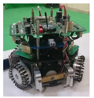
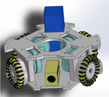
In mechanical design the main parts are driving system, kicking system and dribbling system. Currently, we are using Maxon EC45 30 watt brushless motors in our robots which enable them to have adequate acceleration and speed. Each robot is 179mm in diameter and 146mm in height. A view of mechanical CAD along with a photo of current version of our robots is shown in Fig. 1.
Electrical design
In electrical design we focused on reliability of the boards and also the capability of precise control of driving motors. So a new FPGA-based main board is designed and implemented. Furthermore the kicker board which was one of our major troubles was redesigned and a more robust board one increases system provides the controlling signals to the driving system and kicker module and consists of two separate boards called the main board and the kicker board, respectively. The main reason for separating these parts is to reduce the effect of electrical noise caused by boosting and kicking functions of the kicker board on the other parts.
Main board
The main board is responsible for receiving the data via a wireless module and then parsing these data to meaningful information to control the motors. The packets it receives contain the desired speed of robot wheels, kick speed and type and some other commands. It also sends commands to the kicker board to determine the time and power of kicking. Since 2009 whole the electrical system has been altered. Here is a summary of what we have done in these years.
In 2010 we utilized ATMEGA16 MCU from AVR family of microcontrollers. In 2011 we replaced our main microcontroller with ARM7 family - AT91SMA7X - and then in 2012 we redesigned our main boards based on ARM LPC1768 which provides more professional features. The 100MHz clock speed in comparison to the 50MHz clock speed and a cortex-M3 arm processor provides faster PI calculations for the controller firmware. In this case one of the board's advantages is the ability of easy programming which can be done by an on-board USB 2.0 port. Moreover in new design we are able to program the microcontroller via Xbee wireless modules which is more convenient. We have also changed our motor driving system from the old L298 IC's to MOSFET H-bridges which provide more efficiency and reliability. This new design has the ability to drive both brushed DC and BLDC motors.
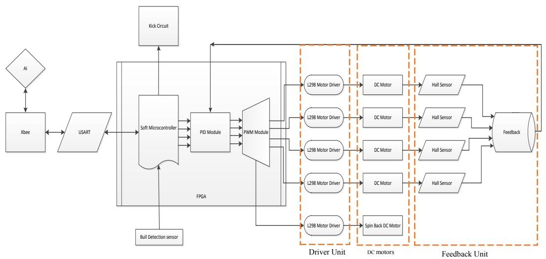
We are currently utilizing FPGA Spartan III family - Xilinx XC3S400 chip - as the only processor on the main board to generate all control signals for all parts such as wireless communication, kicking force, driving and so on. This chip is chosen because of its low power consumption, its high number of available pins and its huge logic gate numbers in comparison with other similar products. The Xilinx Spartan III, with its IP core provides significantly faster computation, when compared to the previous robot MCUs; besides Using FPGA, in addition of real-time benefits, would considerably reduce the number of components on the board and makes the debugging procedure much easier. Fig. 2 represents the relation between FPGA and other units:
Kicker board
We have used advanced boost circuit topology with a current and voltage feedback on our robot's kicker board. The booster charges three paralleled 1600 $\mu$ F-250 V capacitors up to 240 Volts using a voltage feedback to measure the capacitors' voltage and a current feedback to adjust the switching duty cycle. The change that has been made here is that we increased the PWM frequency in order to have a higher efficiency and reduce the loss of energy in the inductor. We also used opto-couplers in order to isolate the control and power parts.
Software System
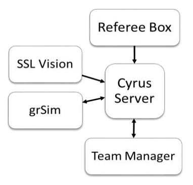
Our software system includes two distinct units. The main processes for decision making are carried out in the server program which is responsible for all levels of decision making in a small-size team. The other unit, namely Team Manager is designed to visualize and monitor the output data of each module in the server program, during decision making process. The main idea for separating these programs is to run graphical processes of this application, on another computer to avoid unnecessary CPU loads on server computer. Using network communication, we can utilize two separated computer to run the programs. The architecture of the software system is depicted in Fig. 3.
We have also developed a mini-app to help the team coach during a game or in tests. The information like robot position, robot target and the path which is planned to run are displayed by this application. Moreover, informing the coach about the fouls happened in the game such as double defender or exceeding ball speed limit is another feature of this tool.
Decision Maker
Our decision maker is designed based on STP Architecture which is proposed by CMDragons in [2]. At the top of this system there are two UDP sockets to make connection to vision and referee systems. We first try to find and eliminate outliers in vision data and then feed it to an alpha-beta-gamma filter to make a good estimation of the position and speed of the objects in the field and update the World Model. As you can see in Fig. 3 in test mode the vision data is captured from grSim (SSL simulator) [3].
For task allocation, we have built a set of strategy files, each one in a script file. A strategy determines the set of robot roles and their parameters. The role assignment is done based on these roles to join each role to a physical agent. Finally each role calls a specific skill for its own agent. The skills which need the robot to travel a free-obstacle path call the motion planner module.
Motion Planner
This year we dedicate noticeable time to design and implement a fast reliable motion planner that could be responsible for providing smooth, safe and efficient actions for robots. Among many solutions for dealing this problem Artificial Potential Fields (APF) APF is a simple and computationally low cost method which keeps the robot away from the obstacles in environment. However, this approach suffers from trapping in local minima of potential function and then fails to produce motion plans. In this approach the force sources are either repulsive or attractive [4].
$$F(s) = F^{att}(s) + \sum_{i=1}^{m} F_{ob_i}^{rep}(s)$$
where m is the number of obstacles in the environment.
However the attractive force alone in this method is not sufficient for navigating the robot toward the goal state in every complex configuration space. This is the key idea for defining a new type of force in the space that directs robot to the goal region through some sub-goals. The robot has to just tries to passes each sub-goal respectively to arrive the main target. This idea results in declaring the directive force.
We have proposed a novel approach which employs a prior path between origin and goal configuration of the robot. Therefore, the planner guarantees to lead the robot to goal area while the inherent advantages of potential fields remain. For path planning stage a well-known approach Rapidly-exploring Random Trees (RRT) is applied.
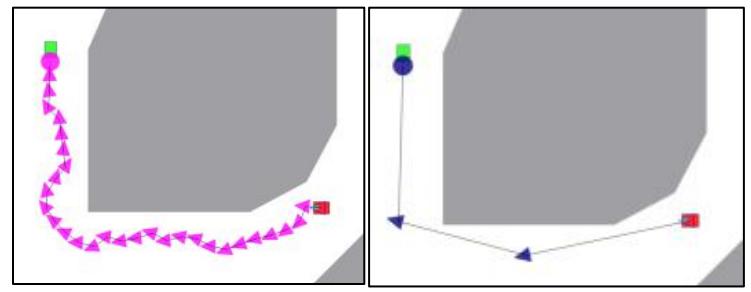
We then try to simplify this path by eliminating unnecessary sub-goals. Thus a primary path like what is depicted in the left picture in Fig. 4 will change to a very simple one, i.e. the right one. We start from the initial node and try to eliminate each node and check whether the new plan is still valid or not. This level is very important to build highly smooth plans.
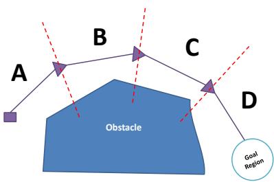
In our definition, directive force is determined based on a prior path which is previously generated by RRT planner. This simple path will divide the configuration space into multiple cells. Each cell belongs to the nearest segment of the prior path.
So within each cell the directive force is applied in the direction of that segment. This is shown in Fig. 5.
The resultant force is calculated by summation of these three force sources.
$$F^{new}(s) = F^{att}(s) + \sum\nolimits_{i=1}^{m} F^{rep}{ob_i}(s) + F^{dir}{seg_j}(s)$$
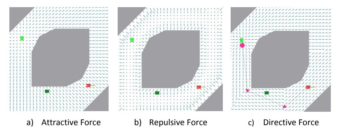
Where $F_{seg_j}^{dir}$ denotes the directive force in position s, which is directed by the j'th segment of the prior path. In Fig. 6 these forces are displayed by small vectors in the space.
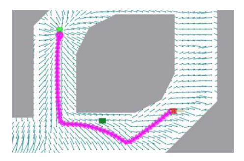
The final plan for above forces is depicted in Fig. 7.
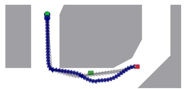
One of the most prominent properties of proposed planner is fast reaction to sudden changes in the environment. During a game most of times it is not needed to reproduce the prior path and just recalculation of the forces and the making the final plan is performed. For example in the following figure it is shown that when a robot plan collide a new object in the field it will repair its plan quickly.
The motion planner will be run every 100 milliseconds, and if the potential field succeed in producing a valid collision-free plan, then there is no need to run timeconsuming RRT algorithm to update the prior path.
Calculating Motor Velocities
Experiences show that a noticeable issue in robot navigation is that the mechanical elements are not ideal i.e. the asymmetric forces between the robot wheels and ground result in imprecise movement of robot. For this problem we have proposed a new algorithm in which the mechanical system is assumed as a deterministic but predictable system [5].
We know that the tangential velocities of 4 wheels are needed to control a robot. A simple way to calculate these values is to use a transformation matrix i.e. write the velocity of each wheel as a linear combination of desired velocities:
$$M_i = aV_{xL} + bV_{yL} + c\omega_{zL}$$
where is the tangential velocity of the i'th wheel and are desired velocities of robot in x axis and y axis and desired angular velocity respectively. On the other hand for an n-wheeled robot the coefficients can be calculated by considering the angle between i'th wheel and the robot's main axis. So we can rewrite the above equation by overriding the coefficients:
$$M_i = -\sin(\alpha_i)V_{xL} + \cos(\alpha_i)V_{vL} + R_R\omega_{zL}$$
where is the robot radius.
What we are looking for is to replace a, b and c with more accurate values to better controlling the robot. Our methodology is to replace these values with a function of desired velocities. Thus we designed a learning procedure to estimate the best coefficients.
In each cycle we build a packet which are normalized random numbers, and send it to the robot, as motor desired velocities. Then we calculate the local speed of the robot from the vision system. Thus we will have a dataset which the input attributes are motor desired velocities and the outputs are observed robot speed. We will fit these parameters by a Takagi-Sugeno modeling algorithm to estimate the best coefficients for a robot to move with any desired speed.
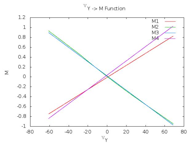
For example in forward direction the plot is like Fig. 9. The different slopes for 4 lines show that the motors have not identical influence on robot movement in this special direction.
References
- Nazemi, B., Raeessi, S., Amiryan, J., JafarzadehPour, A., Mohammadzadeh, Sh., Nikoukar, A., Aali, A., Eskandari, N. (2014) CYRUS 2014 Team Description.
- Browning, B., Bruce, J., Bowling, M., & Veloso, M. (2005). STP: Skills, tactics, and plays for multi-robot control in adversarial environments. Proceedings of the Institution of Mechanical Engineers, Part I: Journal of Systems and Control Engineering, 219(1), 33-52.
- Monajjemi, V., Koochakzadeh, A., & Ghidary, S. (2012). grSim–RoboCup Small Size Robot Soccer Simulator. RoboCup 2011: Robot Soccer World Cup XV, 450-460.
- Warren, Charles W. (1989). "Global path planning using artificial potential fields." Robotics and Automation, Proceedings., 1989 IEEE International Conference on. IEEE, 1989.
- Nazari, Mostafa, Javad Amiryan, and Eslam Nazemi. "Improvement of robot navigation using fuzzy method." AI & Robotics and 5th RoboCup Iran Open International Symposium (RIOS), 2013 3rd Joint Conference of. IEEE, 2013.