ER-Force Extended Team Description Paper RoboCup 2015
Michael Eischer, Peter Blank, Alexander Danzer, Adrian Hauck, Markus Hoffmann, Benjamin Reck, Bjoern M. Eskofier
Digital Sports, Pattern Recognition Lab, Department of Computer Science Friedrich-Alexander University Erlangen-Nürnberg (FAU), Erlangen, Germany; Robotics Erlangen e.V., Martensstr. 3, 91058 Erlangen, Germany
http://www.robotics-erlangen.de/ · https://www.robotics-erlangen.de/publications/jtag-programmer · https://www.robotics-erlangen.de/publications/autoref
Abstract This paper presents proceedings of ER-Force, the RoboCup Small Size League team from Erlangen located at Friedrich-Alexander-University Erlangen-Nürnberg, Germany. We present an innovative, robotbased method of ball detection that uses infrared light reflected from the ball. Recent publications include an updated version of our JTAG-Programmer ERPROG and our software framework. Detailed documentation is provided on our website and in this paper. Furthermore, we share our experiences with our multi-agent system and the path planning algorithm.
Introduction
With RoboCup Small-Size-League using highly standardized mechanical designs and several of them being commonly available, we decided to pass on commenting on the minor changes we made on our design and focus on electronics and software. Hence, find information on our innovative, robot-based infrared ball detection device in section 3, together with the design for the updated version of ERPROG, a JTAG-Programmer. Insights into our strategy, more precisely the multi-agent system and the path planning algorithm are given in section 4 and section 5, respectively. The final part, section 6, introduces all information needed to make use of our software publication.
We hope to advance the league with those topics where it is needed: by facilitating the entry for new teams and by supporting the referee who is unable to follow game scenes that are becoming faster and faster.
Mechanics
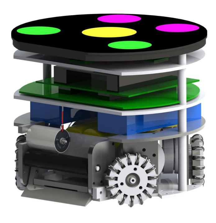
The mechanics design has not changed since last year. See the 2014 TDP [1] for details.
Electronics
In 2014 we realized a complete redesign of our electronics components. This modular design offers us the possibility to renew each component as described in [1] without interfering with the whole architecture. For RoboCup 2015 we are in the comfortable position of having a working system which can be optimized step by step. Especially the ball detection and EMC troubles offer lots of room for improvement. This chapter describes the rework of our balldetection system. Furthermore we decided to publish our optimized JTAG-Programmer as described in the second part of this chapter.
Detecting the ball
A ball detection system is required because the camera system is not able to measure exactly the distance of the ball and the robot. Our approach is to notify the robot if the ball is located in immediate proximity, but have the final ball detection done locally on the robot. The requirements of ball detection systems suitable for this application are listed below.
- No interference with the camera-system,
- insensitive to the field lights,
- fast detection (within 20µs),
- no physical interaction with the ball, and
- failsafe decision between ball detected and system malfunction.
An answer to these requirements is an optical detection system based on infrared light. Find two possible implementations subsequently.
Linear light barrier In the 2012 robot generation a linear light barrier system was used. It was placed in the very front of the bot, below the dribbling device.
An infrared LED (IR-LED) on the one dribbler-side was transmitting a continuous light-beam. The beaming angle was set approx. 6 degree. On the opposite side, a photo transistor received the signal. Figure 1 shows the arrangement.
The electrical architecture of this system is quite simple. For the transmitting side (TX) a resistor and the IR-LED is needed. On the receiving side (RX) there are a photo transistor with a reference voltage source and a comparator with adjustable threshold voltage to create a digital signal for the microcontroller.
The performance of this system proved to be insufficient. The receiver was influenced from other light sources than the transmitter, thus required readjustment of the threshold voltage manually with a potentiometer. Additionally, LED or transistor were physically damaged by other bots. Therefore we decided to implement a better way of optical ball detection.
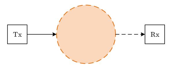
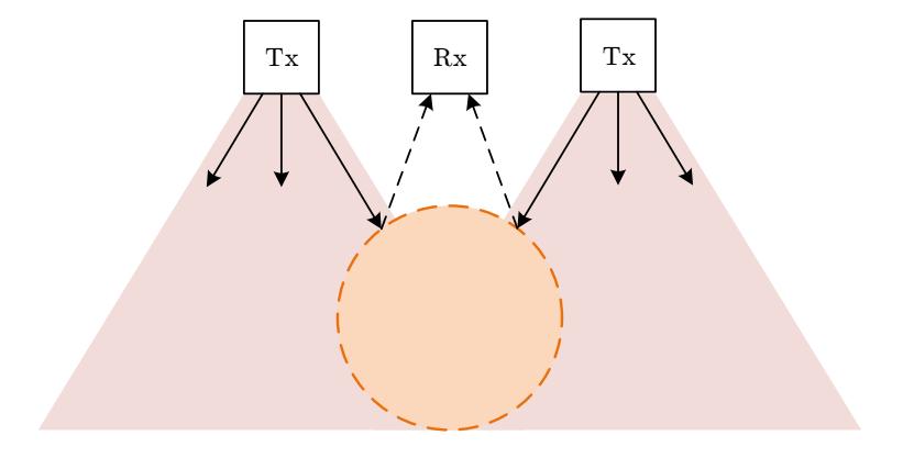
Reflective light barrier The principle of this kind of light barrier is to detect reflected light from a surface. Transmitter and Receiver are next to each other facing towards the detection area. Figure 2 shows the pictorial schematic. This design avoids sensible parts to be located in exposed positions of the bot. The sensor can be behind or above the ball. This prevents mechanical damage of the components and the related failure of the kicking system. Integrated parts are available from Vishay, like CNY70 or TCRT5000. Unfortunately, the detection distance is only specified in a very small range (0 to 15mm). For Sharp GP2Y0A21YK a detection is only possible above 100mm. As our robot-dimensions require a 50mm operating distance, the Sharp sensor is not suitable as well. For that reason, a custom solution was developed and is in use since 2014.
Our first try of a suitable system was in the 2014 robot generation for last year's RoboCup. Figure 3 shows the small PCB with one pulsed IR-LED and one photo transistor with charge amplifier. We tried to use discrete components to be able to optimize the circuit for best performance. The analog sensor output was transmitted as voltage level single-ended via the connecting cable to our microcontroller to read only the triggering level dynamically. It turned out that this design was failure-prone because of small analog current and voltage levels. Difficult calibrations were required and the system worked still quite unstable.
Concerning the problems of last year's ball detection system, two more rules for ball detection systems were defined.
- Integrated part for signal-receiving and -amplification, and
- Only digital signals on cable connection with EMC protection on both ends.
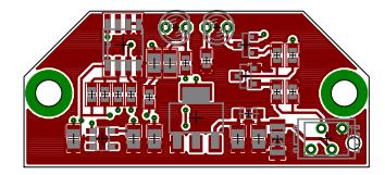
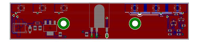
At this moment the further requests are already implemented into a new design. The first prototype is working and shows promising results. Figure 4 shows the 2015 PCB.
The following changes were made in comparison to the 2014 board. The infrared illumination of the whole width of the dribbler is ensured by two transmitting IR-LEDs (Vishay VSMB3940X01) with a beaming angle of 60° each. They are pulsed with 36kHz to fit the specific receiver. The integrated receiver Vishay TSOP1736 processes the signal. It is a standard IR communication IC for remote controls with a carrier frequency of 36kHz. On the output a digital voltage level (one bit) is measured which corresponds to the ball states (ball detected and no ball detected).
These modifications make the circuit very simple compared to the 2014 version. For this purpose and the noisy robot environment the new solution seems to be a better realization without sensible signals on wires across the board. Tests proved our development to be successful and we are highly pleased with the results so far. At the moment, we are experimenting with the position and the light intensity of the LEDs to get the best detection results.
Publication of ER-Force JTAG-Programmer ERPROG
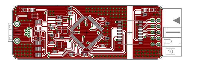
We developed our own hardware to program the ARM microcontroller flash memory on our robot. We use the JTAG standard with a 10 pin connector with the CoreSight 10 pinout, which is described in Table 1. The device is connected via a Mini-USB plug to a computer. FTDI FT4232HL allows for the use of OpenOCD. Figure 5 shows the current board layout.
The benefits of this hardware are the easy USB connection with EMC protection and over-current protection. Furthermore the standard JTAG output with a complete isolation up to 4kV. The target isolation is done by two ISO7231M from Texas Instruments. This device also does a voltage translation which adapts to the target voltage-level. Working is guaranteed from 3.2 to 5.4V. With this circuit the computer is never effected if the programming target fails in any way.
All necessary files can be download from our website with the link given below. We included the EAGLE schematic and 2-layer-board-file, the bill of materials (BOM) with manufacturer and distributor (mainly Farnell) order code and example configuration files for OpenOCD.
https://www.robotics-erlangen.de/publications/jtag-programmer
For the next release it is planned to allow for controlling the isolation voltage translator's enable-pin. Thus, the programmer can be put to high-impedance mode so it does not interfere with the target.
CoreSight 10 pinout
| pin | signal | pin | signal |
|---|---|---|---|
| 1 | VTREF | 2 | TMS |
| 3 | GND | 4 | TCK |
| 5 | GND | 6 | TDO |
| 7 | NC | 8 | TDI |
| 9 | GND | 10 | nSRST |
Strategy
(section_group)
Experience with the multi-agent system
At RoboCup 2014 the transition of our strategy design towards a multi-agent system was completed. We like to give an overview of the implementation and share our experience.
The achievement of the fourth place is the most successful RoboCup participation for team ER-Force so far. Part of the success stems from the radical redesign of the game strategy. Like team Mannheim Tigers [2], which entered the quarter finals for the first time at last RoboCup, we switched from a STP design to a multi-agent system. The key strength of the system showed up in attack situations where we maintained a reasonable defense decoupled from the current move. Also, the passing protocol as described in last year's TDP proved to work reliable without any hard coded positions or game sequences.
One of the more challenging problems with this approach is the coordination of tasks which involve multiple robots like defending the goal at a corner kick.
Organizing the defense in a multi-agent system
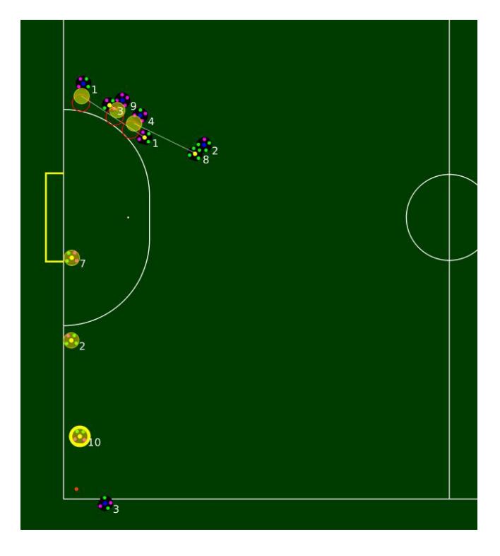
In a situation as shown in figure 6, a crucial requirement is the ability to follow long-term goals like marking opponent robots consistently and being able to react to unforeseen position changes. At the same time, not only the movement of opponents should be considered but also the coverage of the defense area. Clearly, this is a problem which is hard to solve by negotiation protocols. To tackle this issue, there is the trainer component which has an overview of the available defenders and tries to assign appropriate roles. As described in last year's TDP, there is a common communication channel which allows for application and assignment of roles. To avoid collisions and minimize movement distances, the trainer computes all destinations near the defense area and assigns the robots afterwards. It is important to be independent from the concrete number of defenders available. The trainer formulates a single goal involving several robots. This is in contrast to a play of the STP design, which would try to define goals for the whole team and prevent single robots from dissolving into counterattacks while the rest of the team still pursues the defense task.
Path planning
Like with most other teams our path planning is broken up into two steps. First a collision free path is calculated using the ERRT algorithm. Then the found path is processed by the motion control to generate the actual move commands. The following sections detail our usage and modifications of ERRT.
Modeling
Each robot is handled separately, thus providing no direct coordination between robots.
The used state space is two-dimensional representing the x and y-dimension. The orientation φ is not included. As long as the robot is moving freely on the field, this causes are no drawbacks. However the situation changes when approaching the ball, as the robot dribbler is flat. That allows the ball to get nearer to the robots center without actually colliding with the robot hull. Thus additional obstacles and modifications to the robot radius are required.
As the modeling does not include time, an optimal generated path would be the shortest path. This does not necessarily imply that it is also the fastest path.
The obstacle space consists of circles, line segments with round caps and a given width and axis aligned rectangles. As the state space does not contain time, all obstacles are assumed to be at a fixed position. A robot is modeled as a circle with a radius of $radiusrobotA + bound(0, |speedrobotA − speedrobotB| \cdot 0.05, 0.05)$. For opponent robots whose future movement is unknown a larger safety margin is added. Calculating the safety margin between robots based on the speed differences ensures that robots with different movement directions do not collide while allowing two robots moving into the same direction to get as close as possible.
The goal is modeled using line segments, whereas the keeper area is set up with two circles connected with a rectangle. While the stop command is issued by the referee, an extra circle is added around the ball enforcing the minimum distance from the ball.
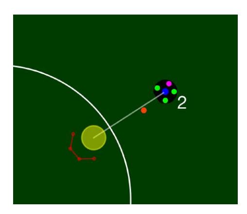
During a game the ball is usually added as an obstacle for each robot. In case the robot is chasing the ball like in figure 7, no obstacle is added. This allows planning a straight path to the ball without trying to plan a path around the current ball position.
In order to allow the robot to move next to the ball, it must be modeled using a smaller radius. That radius must be the "shoot radius" which is the distance of the dribbler mid to the robot center. This would allow the robots sides to touch the ball without detecting a collision. Thus several obstacles around the ball forming a cone are added.
ERRT
The ERRT algorithm (described in [3]) is implemented as bidirectional RRT with a way point cache and using RRT-Connect (see [4]). The bidirectional RRT grows two trees starting at the start and end point. Using RRT-Connect these are not only extended towards the random state but also towards each other.
A kD-Tree is used to speed up the calculations. The simple case that a robot can move straight towards its target is checked first to avoid unnecessary calculations. Just returning the start and end points as a path while being valid is incorrect. This would skip the way point cache what will cause unstable paths whenever an obstacle enters the free path. Thus our implementation splits the line into several small segments using the step size used by the ERRT algorithm. These way points are used to update the cache.
Obstacle handling
RRT based algorithms are designed to find a path from start to end without colliding with obstacles. Due to the dynamic environment and sensor or actuator noise a robot may enter an obstacle which requires special handling.
To allow the path planner to leave obstacles a modified collision check is used:
A position is considered free if the robot (modeled as a circle with configurable radius) can be placed there without intersecting with an obstacle. In case the position is obstructed, that is not free, a path to a new position is valid if equation 4 holds.
$$startObstacles = {o \in Obstacles | o \text{ collides with } pos_{start}}$$
$$otherObstacles = Obstacles \setminus startObstacles$$
$$distInObstacle(pos) = \sum_{o \in startObstacles} \min\left(-distance(o, pos) + robot_radius, 2 \cdot robot_radius\right)$$
$$\forall p \in [pos_{start}, pos_{end}] : distInObstacle(p) \leq distInObstacle(pos_{start})$$
$$\land \neg (pos_{end} \text{ collides with } otherObstacles)$$
[posstart, posend] denotes every point on the line segment between posstart and posend. The implementation just checks a point every 2 millimeters on the line segment. This is sufficient as even the smallest obstacles, the goal sides, are a magnitude larger.
Calculation of distance(obstacle, pos):
• For a circle: |centerobstacle − pos| − radiusobstacle
- For a line: distance to linesegment(obstacle, pos) − radiusobstacle
- For a rectangle (axis-aligned): ( smallest distance to side or corner pos outside obstacle negative distance to nearest side otherwise
The check using distInObstacle ensures that it is not possible to enter further into an obstacle. The second part of equation 4 ensures that no new obstacles are entered.
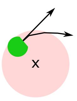
The construction of equation 4 allows sliding along an obstacle. Two possible paths are shown in figure 8. If the new added path segments were infinitesimal short, it would be possible to move along a circle inside an obstacle. As this is very unlikely to happen, each new point will be further outside the obstacle than its predecessor. Allowing small movements inside an obstacle can be beneficiary when trying to keep the required distance to the ball during stop. If the shortest path out of that obstacle is blocked by other robots, an alternative can be found.
While the robot has fully entered an obstacle, it is allowed to move freely within it. This case should only occur if a new obstacle suddenly appears, like the blocked zone near the ball during stop. By limiting the intersection distance the chances to find a path towards the preferred direction are increased. The obstacle used to represent other robots is small enough to prevent the current robot from being fully covered by it. Thus the planned path is always pointing away from the other robot in case of a collision.
If the robot gets moved outside the play field, a similar calculation is used. This allows the robot to reenter the field after leaving.
The condition is applied on both trees thus allowing a bidirectional search even with the end point being inside an obstacle. For extracting the path once both trees touch, care has to be taken to not include points of the tree grown from the target which are inside an obstacle. To allow moving as near as possible to an obstacle, a binary search is used between the last point outside and the first point inside the obstacles. By implementing obstacle handling for the start and end point RRT is also more likely to find a path within the given iterations limit, thus decreasing the average worst case latency.
Handling the leaving of obstacles directly within RRT however has a drawback. The point where the path leaves the obstacles near the start point or enters them near the end point exhibits some random movement. At the start point this is handled by the path post-processing using a simple modification. Improving the end point is more complicated: As end points inside obstacles are cutoff the new end point is noisy and cannot be smoothed that way. This could be mitigated by smoothing the whole path before cutting of the end part inside the obstacle. We have found that the simple cutoff is sufficient, if some care is taken during target generation.
Path smoothing
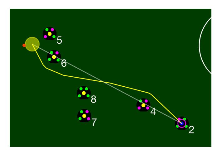
RRT generates jagged paths that require some post-processing. Our implementation uses a simplification and a corner cutting algorithm. Both algorithms are in turn executed three times followed by a final simplification run. This creates smooth paths like the one in figure 9.
Simplification is done using the following algorithm. path is the list of way points.
- for pA in path:
- for pB in reversed(path starting after pA):
- ∗ if the line segment between pA and pB does not collide with any obstacle, then remove all points in between from path
- for pB in reversed(path starting after pA):
The collision check uses the modifications described in the previous section. The simplification algorithm just tries to generate straight lines that skip as many points as possible.
In order to generate a smooth and short path around obstacles the following algorithm is used:
- for pB in path:
- $\circ$ Get predecessor pA and successor pC of point pB
- $\circ$ Calculate $dist = \min(|pB pA|, |pC pB|)$
- $\circ$ Find largest $l \in [0, dist]$ with binary search for which the line segment $pB + \frac{pA pB}{|pA pB|} \cdot l$ , $pB + \frac{pC pB}{|pC pB|} \cdot l$ does not collide with any obstacle
- $\circ$ replace pB with these two points
The algorithm cuts off corners symmetrically. This ensures that smoothing does not differ if the path direction is flipped.
Software Framework
An important change in the rules of the SSL was made 2012 with the restriction of ball velocity to a maximum speed of $8\frac{m}{s}$. From this point robots were not able anymore to score from any place on the pitch. This led to a profound change in the strategy of the teams from programmed static situations towards more dynamic game plays like passing. A problem which arose from the change of the rules was the necessity of a appropriate system to measure the ball velocity. Different systems have been used by the teams on the last years RoboCup competitions. Self designed light barriers were brought to the competitions by the teams. We found that they have great disadvantages. The main problem is, that these devices only can be used before a game for the purpose of calibration. During the game they are inappropriate for monitoring the ball velocity. Thus it was a hard job for the referee to decide by eye whether the ball speed was higher or lower than the permitted limit. So we came to the conclusion that only a system using the images delivered by the cameras to calculate the ball velocity would fit into the requirements for an adequate surveillance system.
Some teams already had implemented software to calculate and show ball velocity on RoboCup 2014 in Brazil. But none of these systems was capable to become a common system for the whole SSL, because most of them were part of the teams frameworks. The system of ER-Force became a commonly trusted and accepted system on RoboCup 2014. Thus we decided to publish our software framework, named Ra, this year, excluding of course our strategy software. We published Ra with regard to the GNU General Public License 3. The software can be downloaded through the following link:
https://www.robotics-erlangen.de/publications/autoref
Introduction into the framework
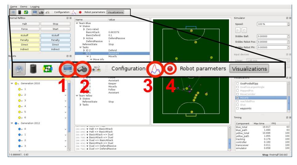
Besides the feature of measuring the ball velocity, Ra offers many other opportunities to the teams of SSL. Connected to SSL Vision, Ra will handle the Vision packages and display them appropriately. Furthermore an AI runtime, implemented in Lua, is included as well so that a team can load its own strategies. Another important feature is the simulation tool. One invaluable treasure for ER-Force team was the game logger. We could investigate our strategies decisions after a logged game simply by watching it in the Logplayer, included in the software package as well. Figure 10 shows the graphical user interface of the software with a zoom to the small strip with buttons at the top. With Button (1) one can switch on simulation. Button (2) is to turn on the internal referee. After pressing Button (3) the plot window will show up with a lot of plot functions, including the ball velocity. Note that the ball velocity is not only calculated by simply looking at the positions delivered by SSL Vision. A Kalman filter is used to reliably filter the noise of the camera. Button (4) is used to toggle the logger. The file automatically created during a game can be loaded with the logplayer.
Conclusion
Having published a first version of the automatic referee system, we would appreciate the support of other teams in order to establish a better method to obtain fast and correct decisions. The challenge opens a complete new field of research possibilities for the teams. Having said that, we are very happy to help new teams having any issues with published system parts. New teams entering the league are crucial for the survival of SSL, so we invite everyone to contact us with any requests.
In the past, the characteristics of SSL have been pointed out over and over again - entry league, many students. This applies to our team as well. The number of lessons learned by building a SSL team is by far higher than it is in traditional lectures. Unfortunately, many students are not given any credit points by their universities. This leads to the uncomfortable situation of doubled workload by traditional classes and the approach of RoboCup deadlines, reducing quality of the SSL systems. We would welcome a push of the RoboCup committee into this direction.
References
- Bayerlein, H., Danzer, A., Eischer, M., Hauck, A., Hoffmann, M., Kallwies, P., Lieret, M.: Team Description Paper for RoboCup 2014 (2014)
- Ryll, A., Ommer, N., Geiger, M., Jauer, M., Theis, J.: Tigers Mannheim TDP for RoboCup 2014 (2014)
- Bruce, J., Veloso, M.: Real-time randomized path planning for robot navigation. In: IEEE International Conference on Intelligent Robotics and Systems, IROS '02, Switzerland (2002)
- Kuffner, J., LaValle, S.: Rrt-connect: An efficient approach to single-query path planning. In: IEEE International Conference on Robotics and Automation, ICRA '00, 2000. Volume 2., USA (2000) pp. 995–1001