KIKS 2015 Team Description Paper
Tetsuya Sano, Soya Okuda, Kosuke Matsuoka, Yu Yamauchi, Hayato Yokota, Tatsuro Sakaguchi, Masato Watanabe, Toko Sugiura
National Institute of Technology, Toyota College Department of Electrical and Electronic engineering, 2-1 Eisei-cho, Toyota Aichi, 471-8525, Japan
http://www.ee.toyota-ct.ac.jp/~sugi/RoboCup.html
Abstract This paper is used to qualify as participation to the RoboCup 2015 small size league. Our team's robots and systems are designed under the RoboCup 2015 rules. The major points of improvement in this year are improvements about the performance of driving wheels, electrical circuit and AI system. The overviews of them are described.
Introduction
We have made soccer robots since 2002. We still have problems with a strategy, an electrical circuit, and their kinematic performance. One of the serious problems is that the success rate of their passing a soccer ball is low. Our robots can pass the ball worse than those of other teams, so that robots which receive the ball often can't catch it successfully. As a result, our team is late for making a smart strategy. In order to solve the problem above, we attempted to improve our robots in 2014 so that they can pass perfectly.
First, we attempted to improve the ability to pass and receive the ball precisely by making robot's driving wheel and the ball sensor outskirts better. Second, we made our robots catch the ball more precisely by enhancing the ability to predict where the ball reaches. The main improved points are as follows:
- Improvement of the driving wheels
- Improvement of the electrical circuit
- Improvement of the AI system
Hardware of the robot
Performance of our robots
Specifications of our robot made in 2015 are shown as Table 1. Its weight was lighter than 2014 model. Furthermore, its height and center of gravity are lower by using of flat type solenoid. The other mechanical elements are the same as the previous year.
Specification of the robot (comparison with 2014 model)
| 2015 version | 2014 version | |
|---|---|---|
| Weight | 1.9kg | 2.3kg |
| Material | Aluminum alloy | Aluminum alloy |
| Driving motor | maxon EC45 flat (30watt) | maxon EC45flat (30watt) |
| Driving gear ratio | 4.0 : 1 | 3.6 : 1 |
| Wheel diameter | 50mm | 56mm |
| Number of solenoids | Straight kick: 1 Chip kick: 1 |
Straight kick: 1 Chip kick: 2 |
| Straight kick power | Ball speed of 8m/s | Ball speed of 8[m/s] |
| Chip kick power | 3.0m away from robot | Max 3.0m away from robot under the condition of initial angle 40° |
| Dribbling motor | maxon EC-max22 | maxon EC-max22 |
| Dribble-roller diame ter |
15mm | 15mm |
| Dribbling gear ratio | 1.2 : 1 | 1.2 : 1 |
Travelling performance for the wheel
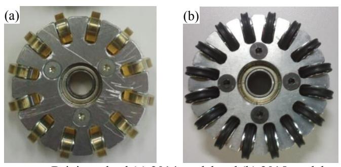
The wheel used in 2014 has a superior performance in its durability, but the width between each small ring-tire had a bad influence on its kinematic performance in that it caused the vertical vibration. It also caused a malfunction of a circuit and induced the noise of its acceleration sensor, which negatively affected the durability of the robot.
Therefore, as shown in Fig. 1, the wheel was improved by increasing the number of small ring-tire to make a shape of the wheel close to a perfect circle. Moreover, the grip power of wheel was enhanced by using of X ring as small ring-tire of wheel.
For kick device
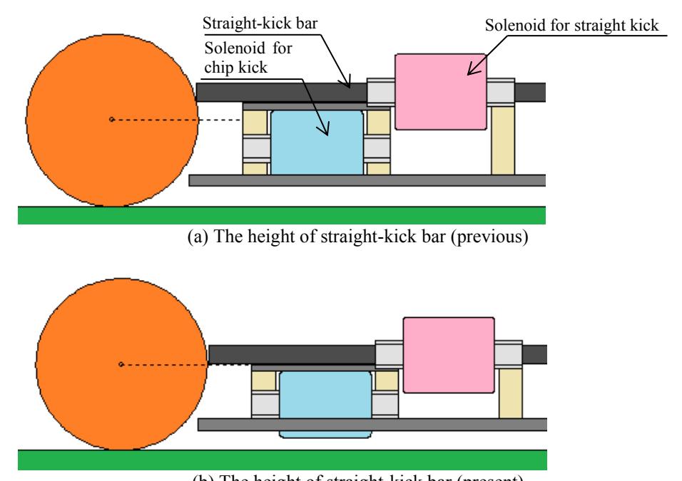
When we used straight kick last year, sometimes the ball bounced and we couldn't kick the ball at the designed speed. A close investigation of the cause reveals that it is attributed to the fact that straight bar kicked the ball at higher a center position of the ball.
The kick device we made last year is shown as Fig. 2(a). The solenoid for straight kick bar is set on the solenoid for chip kick bar in our robots. In Fig. 2(a), the straight kick bar kicks the ball, which induces a bound of the ball. In order to make this situation better, we reduced the number of turns of solenoid for chip kick and set straight kick bar at a lower position by lowering the height of the whole solenoid. The improved device is shown in Fig. 2(b). It is confirmed that the ball that is kicked out from the device doesn't bounce and moves in stable orbit. Furthermore, the experiment we made reveals that the reduction of the number of turns has little influence on the distance of the chip kick. The result for this is the chip kicks the ball at a little lower position, which can touch the bar to the ball more extensively and conduct force efficiently.
Electrical design
Development of new ball-detecting system using ranging sensor
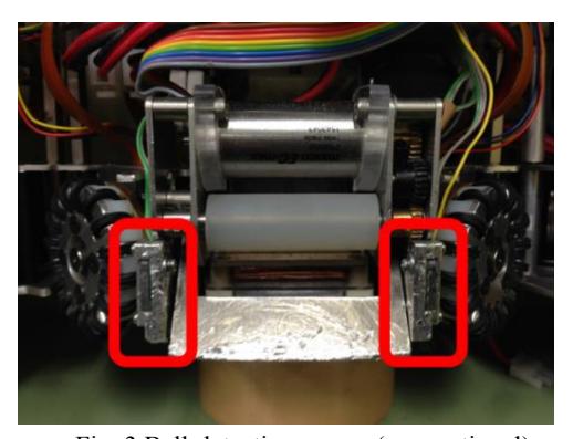
Existing ball sensor is arranged on the both sides of the catching part in front of the robot as shown in Fig. 3. When the ball enters between an infrared-emitting diode and a photodetector, the sensor reacts. But a sensor's convex portion structure may prevent reacting on ball. That is, there are cases that robot can't catch the ball when the ball coming from robot's slant, left and right hits a sensor's convex portion structure. So we used infrared distance measuring sensor unit to improve performance of catching the ball.
Shown as a situation that robot gets a sensor in Fig. 4(a), and infrared distance measuring sensor unit in Fig. 4(b). This device outputs the voltage corresponding to the detection distance and digital I2C data. We added IC2 host module to existing circuit board, and put this sensors on two points of the robot's front. As a result, we checked the robot could catch the ball with more huge area than the previous situation. Now, we put these sensors into some robots, but we can't use data of distance. In the future, we expect to get data of position and data of distance between robots and the ball from two sensors, therefore we expect to use data for single robot's attacking and defending without server's orders.
![(a) new ball-sensor mounted on a robot and (b) distance measuring sensor unit [SHARP GP2Y0E03]](/tdps/soccer_smallsize__2015__KIKS/_page_4_Figure_0.jpeg)
Introduction of bidirectional communication
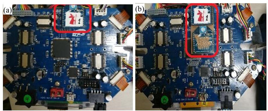
The previous communication between AI server and robots is simplex to send orders from AI server to robots. We use only Xbee module to send data as shown Fig. 5(a), but as discussed above, we have to incarnate duplex to send data from distance measuring sensor to a server. So we made the environment for the reception in AI server and add 2 Xbee to robots modules for sending and receiving to use duplex. The picture of situation that robot has 2 Xbee is shown as Fig. 5(b). So far, a Xbee receives orders from server, and another sends situation of ball sensor's reacting. We use information sent from robots to check robot kicked or didn't. We can check receiving data in server. The previous situation, there was only way to research distance between robots and balls from SSL vision if we want to know state of robot's catching the ball. So if robots don't have the ball, robot may blank shot because of sensor misrecognition. If robots send situation of catching the ball to AI server, we can reduce blank kick the ball. Therefore, if we know where the ball is existing on a catching devices, we can use the data efficiently to expect where the ball is going.
Improvement of the program for receiving a pass
In the recent SSL League, with the extension of the soccer filed, more accurate and frequent passes are required for scoring a goal. Our previous robots had a low success rate of receiving a pass owing to their mechanical accuracy and structure. The robot making a pass was unable to kick straight through to the robot receiving it. Also, the latter was unable to receive it because of the projection portion of the ball sensor or the chip kick bar as well as the insufficient prediction of the orbit estimation of the ball from the former.
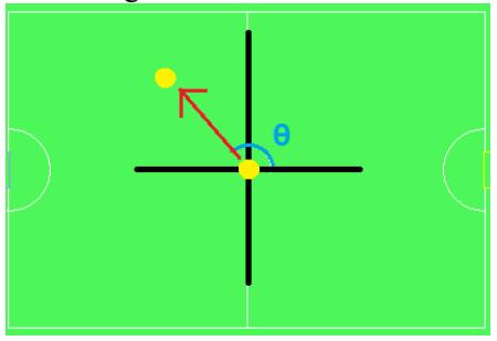
This year, we used Kalman filter in order to improve this prediction and calculated the angle for the direction of a ball from the difference of the position between before and after it moved. It is shown in Fig. 6. The angle of the blue arc shown in Fig. 6 is defined as angle θ.
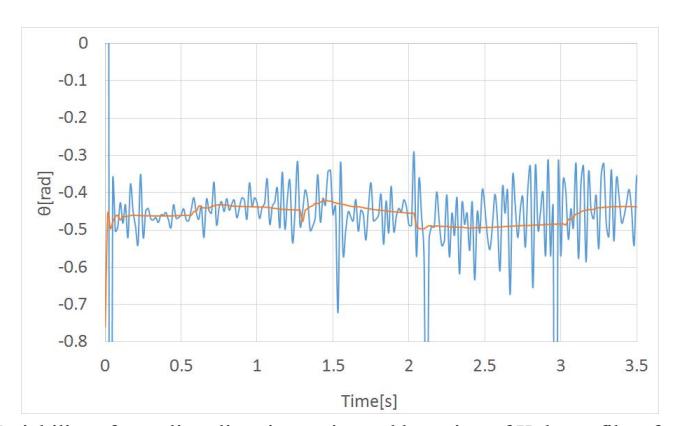
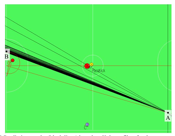
The estimated result of the direction of a ball is shown in Fig. 7. The red line in Fig. 7 shows the result after Kalman Filter was used. Before the filtering, we can detect vibrational component which hinders the calculation of the direction of the ball, while after the filtering, the vibration amplitude falls inside the range within 0.1 [rad]. Figure 8 shows the prediction result of the target position in each frame based on the result after the filtering. The black line in Fig. 8 shows the ball is kicked from the lower right point A to upper left point B near goalpost, which proves that the prediction of the orbit estimation of the ball is more accurate than before. The solid lines which deviated from the target significantly were drawn at the initiation stage of the experiment when the ball a robot started to kick bounded. Under the existing conditions, a robot can only make a pass when it is in a resting state. The development of the robot making a pass while moving remains to be solved in the future.
Conclusions
Continuous improvement has been made to our robots every year. We hope they will perform better in this coming competition.
References
[1] Ryu Goto et al.: KIKS 2013 Extended Team Description, 2013 [2] K. Fukunaga: Introduction to Statistical Pattern Recognition, Academic Press, 1972. [3] James Bruce and Manuela Veloso: Real-Time Randomized Path Planning for Robot Navigation, Intelligent Robots and Systems, 2002. IEEE/RSJ Int. Conf. Intelligent Robots and Systems, pp.2383-2388, 2002.