KN2C 2015 Team Description
Milad Abaierad, Mina Mobahi, Fatemeh Ghofrani, Vida Zolghadr, Mohsen Raoufi, Sara Biglari, Mohammad Reza Karimi Dastjerdi, Mohammad Amin Kashi
K.N.Toosi University Of Technology, Faculty of Electrical Engineering, Advanced Robotics & Automated Systems(Aras) Lab, Tehran, Iran
https://www.github.com/kn2cssl
Abstract KN2C Small Size Soccer team, with more than five years of experience, is planning to participate in 2015 world games. In this paper we present an overview of KN2C small size team.
1 Introduction
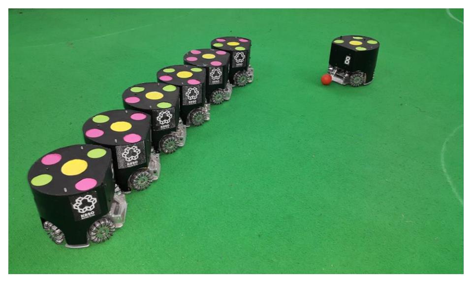
"KN2C" small size soccer team, founded in 2009, is part of Advanced Robotics and Automated Systems (Aras) Lab. The purpose of this team is to design and build small size soccer robots for participating in International Robocup competitions. This team has participated in four Iran Open Small Size League competitions. In this paper we first introduce our new electrical system. Our robots' Mechanical system will be discussed in section 3 and software and control will be covered in section 4.
2 Electronics
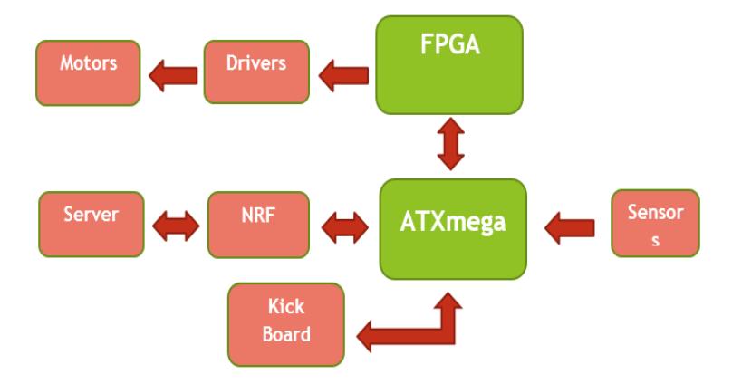
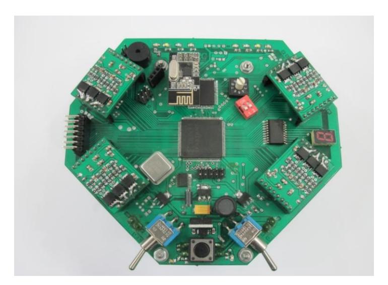
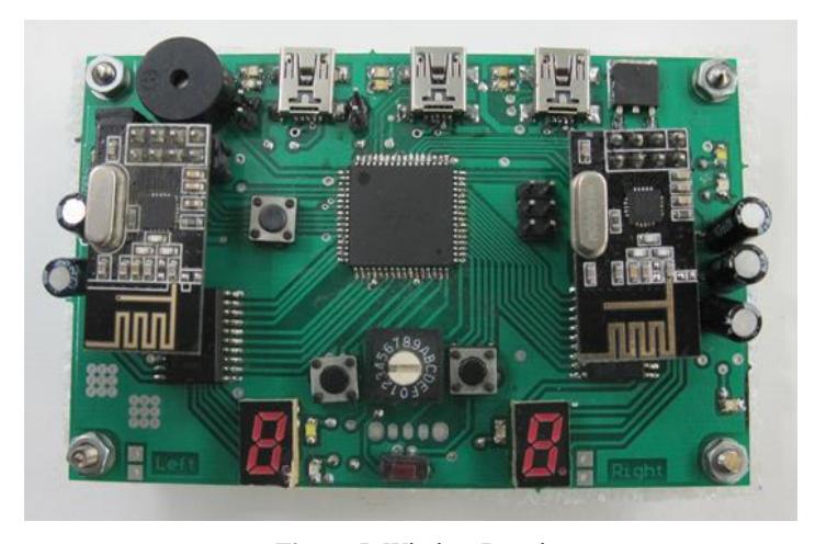
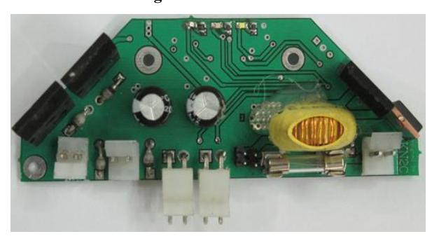
Electronic design has been completely changed since last year. Each robot consists of a main board, four driver boards and a kick board, each of them will be introduced in the following.
2.1 Main Board
In each main board an ATXMega64A3U Microcontroller (from AVR Family) is used to receive data from computer and process part of data in robots. This 8bit Microcontroller has a low-power consumption. The internal architecture of this microcontroller is RISC, with 1MIPSPer MHz processing power and 32MHz operating frequency.
Considering past version of robots problems, such as its imbalance operation because of using four ATmega88 Microcontrollers to drive motors, we decided to use a FPGA XCS400 processor from Xilinx Company instead. FPGA processor, due to its ability of parallel processing, is a good replacement for driving motors and implementing the controller loop. It receives the speed of each motor from Microcontroller.
2.2 Motor Drivers
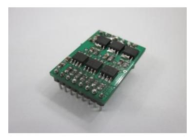
Four BLDC Motors (Maxon EC45 Flat Motor) 30W have been driven by 4 inverter boards using hall sensors.
2.3 Wireless communication
nRF24L01P modules are used for wireless communication between computer and robots. Operation frequency of this module is 2.4GHz and could be changed in range of 100MHz. This module works in SPI communication protocol. In this communication, motors speed, kick speed and robot ID are sent from computer to robots. Battery voltage and kick sensor signals are sent from robots to computer.
2.4 Kick Circuit
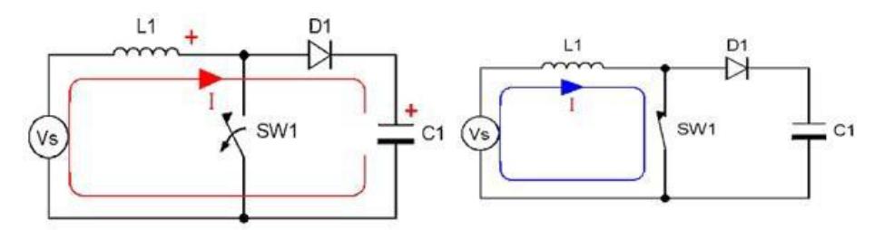
In kick circuit in order to achieve the proper speed, two parallel capacitors (200V, 2200uF) are charged to the desired voltage level using a Boost circuit. Then the microcontroller from the main board produces PWM wave to give the order of straight or chip kick.
3 Mechanics
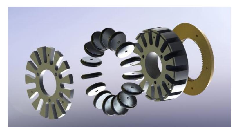
This year nearly no changes have been made to mechanics [1]. Robots have 4 Maxon EC45 Flat motors. These motors are 12V, 4200rpm and 30W. Diameter of the motors is 45mm and their length (including the length of encoders) is 4cm. With these dimensions it was simple to place four motors in each robot. Motors Gears are placed inside the wheels with 8.3:1 ratio. Considering these, our robots are capable of moving forward up to 3.5 m/s.
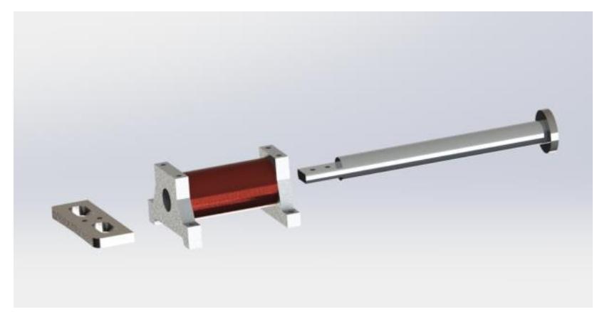
Both direct and chip kicks are designed in the robots. For direct kick we used a solenoid with 8 round of 23AWG wire and for chip kick we used 6 round of the same wire. This way robots are able to kick the ball up to 8 m/s in direct direction and 2.5m distance with chip kick.
4 Software
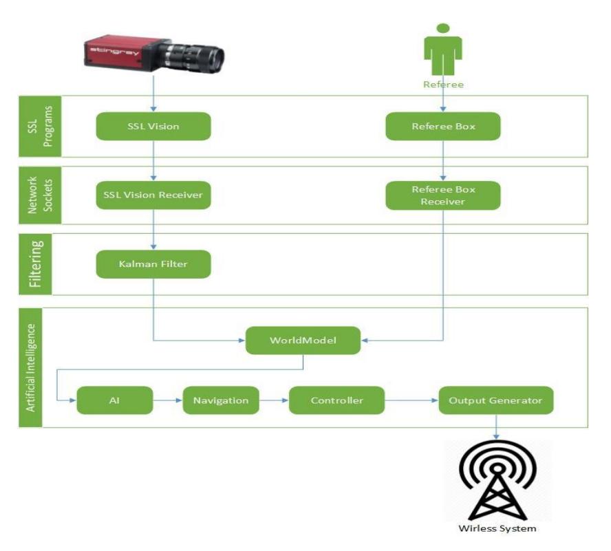
We write our codes in C++ Programming language using Qt framework. The decision making system wasn't changed this year. It's based on STP [2], presented by CMDragons. A view of software system is shown in Fig.10. We use two UDP sockets, one of them for receiving SSL vision data and another one for receiving referee commands. After data filtering, a world model is generated by filtered input data. The world model is given to AI for deciding the way of play. After AI took its decision, it uses Navigation and controller modules for generating final commands, which will be sent to each robot over wireless system.
4.1 Navigation
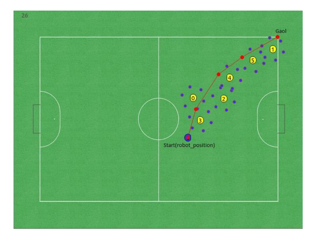
Our navigation system is based on A* search algorithm. A* uses a best-first search and finds a least-cost path from a given initial node to one goal node. For each robot we consider six points around it as neighbor nodes, See Fig. 11. Here is the pseudo code of A* search algorithm:
function A*(start,goal)
  closedset := the empty set;
      openset := {robot_position};
      came_from := the empty map ;
      g_score[start] := 0;
      f_score[start] := g_score[start] +
heuristic_cost_estimate(start, goal);
  while openset is not empty
  current := the node in openset having the lowest f_score[]
 value;
  if current = goal
  return reconstruct_path(came_from, goal);
  remove current from openset
  add current to closedset
  for each neighbor in neighbor_nodes(current)
  if neighbor in closedset
  continue;
  tentative_g_score := g_score[current] +
dist_between(current,neighbor);
  if neighbor not in openset or (tentative_g_score <
g_score[neighbor])
  came_from[neighbor] := current;
  g_score[neighbor] := tentative_g_score;
               f_score[neighbor] := g_score[neighbor] +
heuristic_cost_estimate(neighbor, goal);
  if neighbor not in openset
  add neighbor to openset;
  return failure;
 function reconstruct_path(came_from,current)
  total_path := [current];
  while current in came_from:
  current := came_from[current];
  total_path.append(current);
  return total_path;
4.2 Offensive Positioning
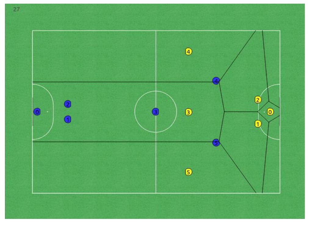
In attacking situations, the positions of attackers are so important. They should be in the positions which can receive pass easier. Also the points should be as far as possible from opponent defenders. This year we use Voronoi diagram for offensive positioning.
Voronoi diagram is a partitioning of a plane into regions based on distance to points in a specific subset of the plane. That set of points (called seeds, sites, or generators) is specified beforehand, and for each seed there is a corresponding region consisting of all points closer to that seed than to any other.
We use opponents' positions as input for Voronoi diagram and find vertices of the diagram. We choose best points from these vertices for our attackers' positions. You can see output of Voronoi diagram in real field in Fig. 12.
4.3 Control
Controlling of each robot consists of two stages. First stage controls robot's motions, direction and its speed and also increases its accuracy in positioning. Feedback of vision feeds this stage of control system.
The output of this controller is X and Y speed of the robot.
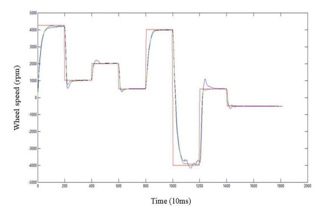
Second controller is assigned to reach the set point which is generated from output of first controller. This controller, controls the speed of the wheels.
In second controller we've used a PD core controller in addition of a coefficient tuning system (CTS). Which adjust proportional gain and derivative gain.
This figure shows differences of a fairly perfect tuned PID controller (blue) and PD core controller with CTS (green) (setpiont red).
Feedback of second stage is obtained from Hall Effect sensors.
Some important numbers in our controlling system:
- Refresh rate of vision: About 15 ms
- First controller stage loop time: About 15 ms
- Data transferring delay time: about 3ms
- Second controller stage loop time: about 1 ms
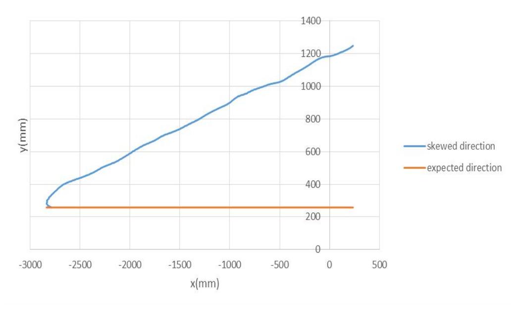
One important point about vision feedback is that if we have a long delay in receiving data from camera then in combination of rotation and displacement speeds of a robot in a certain direction, say x, then we see a diversion in direction of displacement.(more rotational speed ,more skewed direction)
4.4 User Interface
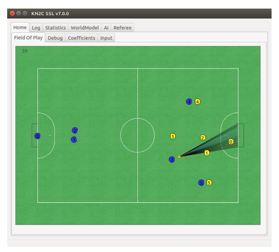
Although our last UI had the ability of show each robot's position, but we realized that it's not enough for debugging our algorithms. So we decided to add new features to Our UI for More Visualizing. We visualize these options in our new UI:
- Output of Navigation Algorithm
- Offensive positions for each robot
- Marked opposite robots
- Goal opportunity for each attacker, See Fig. 15.
4.5 Simulation
Robot software development usually requires a full functional real robot, however due to the hardware problems, which experimental robots always suffer from, it's hard to design software during hardware development process. In addition, when a full functional real robot exists, constraints like cost, maximum operation time and possible damages slow down the software development process. Robot simulators can overcome such problems. According to these problems, we use grSim to simulate the SSL games.
grSim is a multi-robot simulation environment designed especially for RoboCup small size soccer robot domain. It is able to completely simulate and visualize a robot soccer game with full details. Teams can communicate with the simulator in the same way they communicate with real world, except the commands should be sent to the simulator via network instead of radio connections to the robots [3].
5 Conclusion
In this paper, we presented the last improvements of KN2C SSL team. We tried to cover all of details as many as possible, and also decided to publish all of our projects under an open source license, GPL3. So you can find all of our software, PCB designs and everything in this address:
https://www.github.com/kn2cssl
We will be appreciate if we can help any of SSL community members, so every questions is welcomed.
References
- Milad Abaierad, Mina Mobahi, Fatemeh Ghofrani, Vida Zolghadr, Mohsen Raoufi, Sara Biglari. "KN2C 2014 Team Description." In: Proceedings of Robocup 2014.
- Browning, Brett, James Bruce, Michael Bowling, and Manuela Veloso. "STP: Skills, tactics, and plays for multi-robot control in adversarial environments." Proceedings of the Institution of Mechanical Engineers, Part I: Journal of Systems and Control Engineering 219, no. 1 (2005): 33-52.
- Monajjemi, V., Koochakzadeh, A., Ghidary, S.S. grSim RoboCup Small Size robot soccer simulator. In: Röfer, T., Mayer, N.M., Savage, J., Saranlı, U. eds. (2012) RoboCup 2011: Robot Soccer World Cup XV. Springer, Heidelberg, pp. 450-460