OMID 2015 Team Description
Javad Rahmani, Ali Damirchy, Ali Khanjani, Hamid SheikhPoudeh, Omid Mahdizadeh
ECE Department, Shahed University of Tehran, Iran
Abstract This paper is explanation of OMID 2015, Robocop small size team, technical estate and robots technical improvement which generally divided into three part: Mechanical part, Electronic part and Software part.
1 Introduction
Omid Robotics Team has started small size league activities in summer of 2007, as a branch of robotics society of ECE department of Shahed University. Omid robotics team endeavor to accept new member as substitution due to create adequate situation for enthusiastic students every year. Now 3rd generation of Omid robotics team is working hard to achieve more success.
According to last competition (Iran Open 2014) and the problems we confront, some improvements were done:
- Communication module data rate problem.
- Improving robot's inner controlling system.
- Optimizing robot's FPGA codes.
- Changing Batteries.
- Designing and setting new boards.
More details added in related part.
2 Mechanical Design
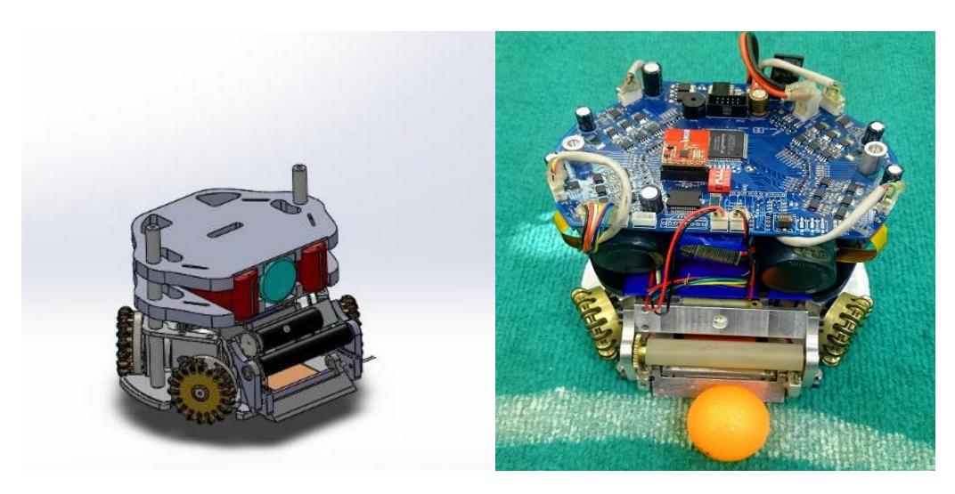
According to Small-Size League rules the robots must have specific dimension, our robots have 178mm of diameter and 148mm of height and also each robot covers less than 20% of ball. The whole robot is about 2 kilograms in weight. 3D simulation models which is shown in Fig.2 are created with SolidWorks.
2.1 Driving System
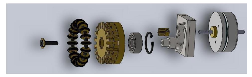
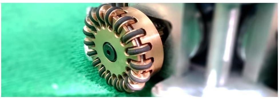
The main chassis of robot is made of Aluminum. 4 Omni-directional wheels carry the main body, each wheel is coupled to an EC-45-Flat brushless 30 watt motor via an inverse gear with a transmission ratio of 1:5. These Wheels are designed in one piece completely and no screws have been used in the structure of wheels. This feature causes more efficiency, more life time and simplicity in design.
2.2 Kicking System
There are two solenoids that help to kick the ball, one for direct and the other for chip kick. A flat plunger is made of steel and has 4mm thickness. Direct kick plunger is made of two materials. The first part material is magnet which is steel, and the second part is made of a material with no magnetic property such as Aluminum. This feature causes a powerful kicking system.
3 Electrical System
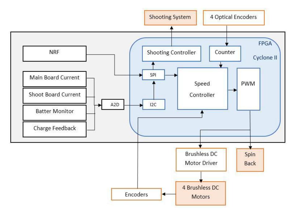
Robots consist of three general parts: Communication, main board and kick board. In the main board we have FPGA Cyclone II [1], motor drivers and etc. A 4-cell li-polymer battery (2200 mAh) is used as a power supply. Block diagram of robot's electrical hardware and software is shown in Fig.3.
3.1 Communication module
The communication between robots and computer is performed by nRF24L01+ module [2]. The nRF24L01+ is a single chip 2.4GHz transceiver with an embedded baseband protocol engine, suitable for ultra-low power wireless applications. The nRF24L01+ is designed for an operation in the world wide ISM frequency band at 2.400 - 2.4835GHz.
In the last competitions we confront with interrupting between Robots and Computer and low data rate. In order to solve the problem we use Logic analyzer to check nRF24L01+ more evidently. Finally we reached the conclusion that the human body between computer and robots cause interruption and it happens in the field alternately. So we use nRF24L01+ with an amplifier for each robot. As a conclusion our data lost reduced and we make reliable communication in double size field.
3.2 Main Board
In the main board we use FPGA (cyclone II) as central controller that controls the motors and shooting system by producing PWM. The new board doesn't have too differences from the previous one in schematic design but the appearance of the board has changed and some PCB designing points were applied.
In FPGA we do some code optimization and change velocity controller [3] with a torque controller [6] for each wheel.
![Fig. 4. Torque controller [6] block diagram](/tdps/soccer_smallsize__2015__OMID/_page_4_Figure_1.jpeg)
3.3 Shooting System
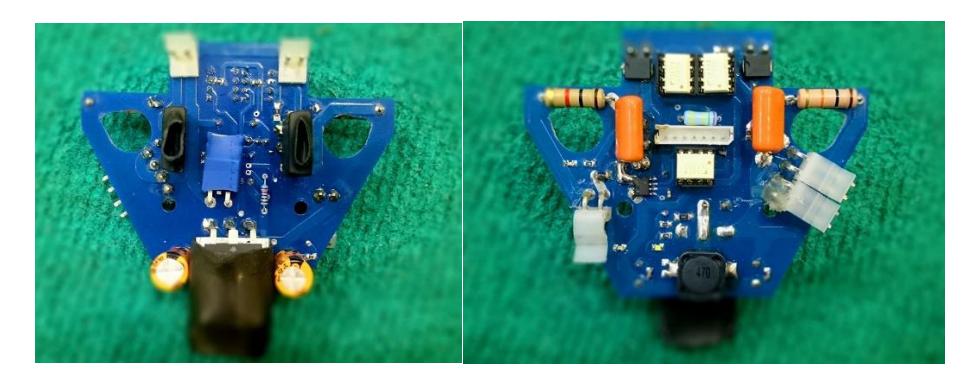
Because of the space limitation on robot we forced to design a new shooting board which is smaller and more efficient than previous one.
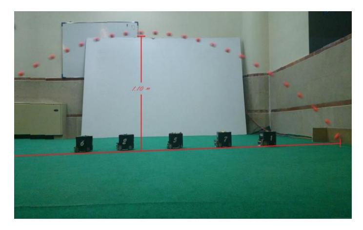
There are two kickers, a direct kicker and a chip kicker. We developed the flat kick system to kick in maximum velocity, approximately 8 m/s. The kicker board can charge two $2200\mu F$ capacitors from 0V to 250V in about 13 seconds with 1A average current. For controlling input current and shooting board current we used ACS712 current sensor. In charging moment a PWM is used, the PWM and Duty Cycle changes is depend on the capacitor voltage's percentage. In order to avoid IGBTs break down in shooting moment we use RCD-snubber [5], [9], [10] as secondary Circuit ,that damp extra current.
4 Computer Software
The computer software is separated into two main sections. Algorithms with User Interface and controlling system.
4.1 Algorithms & User Interface
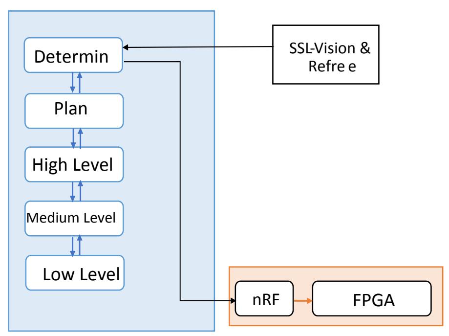
Algorithms structure contain four basic parts: 1) Plans 2) High Level 3) Medium Level 4) Low-Level
Entirely we classify functions in these four parts in order to making programming more simple and flexible.
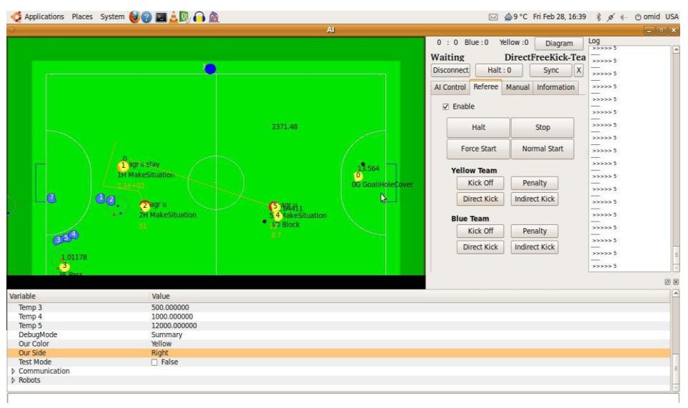
In order to monitor the status of each robot and control all robots in the game field, A monitoring Software has been programmed that will be installed on the off board controlling system. The software receives robots' location and ID on the field from the visioning software and simulates it. In other word this software manages the game play.
In Algorithms part we suffice to code optimization in order to reduce calculation loops and keep old algorithms and layer structure of software. And in the same way for user interface, we just fix some problems.
4.2 Navigation
For navigation of robots we use random rapidly tree (RRT) as a path planning with some customization that limits random trees in order to reduce calculation time.
In the time optimization part we use Bang-Bang trajectory [11] and PI coefficient in the some cases (when high accuracy is needed like direct kick or penalty).
Nevertheless, observation results wasn't eligible, so we review whole system and system's delays. We found out an important delay which was not being covered (around 0.3s). This delay was causing our AI software to observe the game 0.3s later than real-time. To cover this delay and put AI system in real-time we chose to add robot's position (ΔX) to their observed position (X) by each wheel velocity feedback from robots to AI.
4.3 Motor Controller tuner
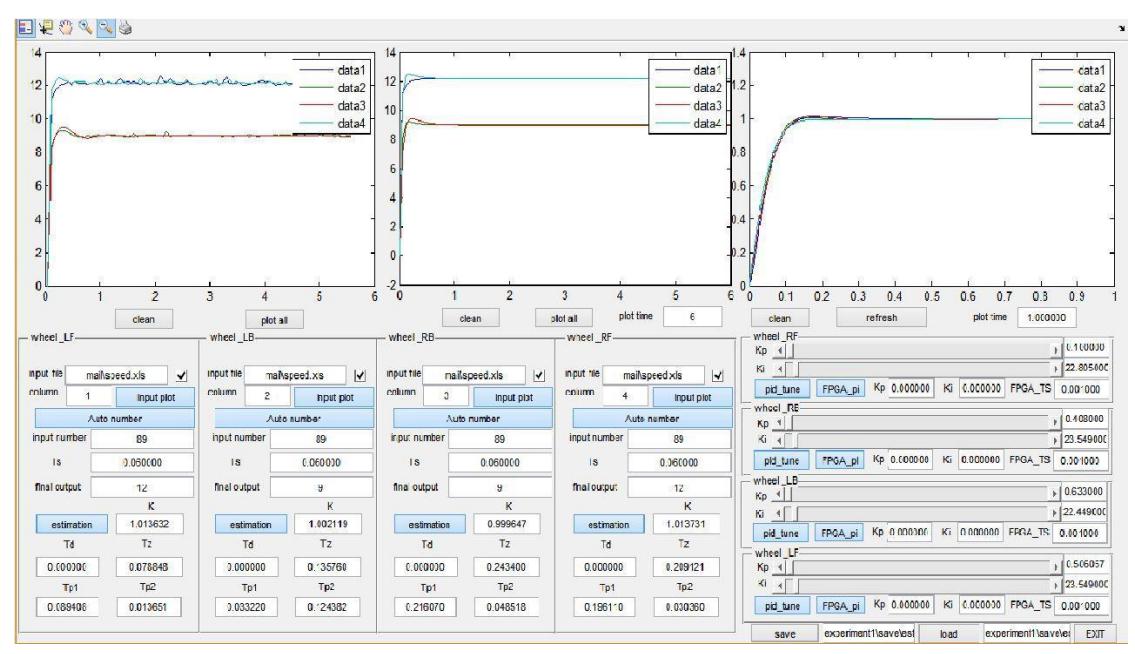
Due to important problems in controlling robots we spent more time on this issue and redesigned it. For making this part better than before we programed a software in MATLAB to receive, save and analyze motor velocity. With the velocity of motor which transfer by nRF, in first step, open-loop transfer function of each motor will be available. Then MATLAB's own pi tuner calculates coefficients.
But obviously the best transfer function (optimized for time rise) for old motors is different and causes an error in robot' global movement. So we need the motors which have the same closed loop transfer function. when motors have the same functions so they behave the same , therefore we add ability to change the coefficients manually and see the results in diagrams. Curves should be coincident two by two (because wheel's angle).
With this ability we reduce most of the global movement errors in the robot.
References
- Altera. : Cyclone II Device Handbook.
- MathWorks. : Learning MATLAB.
- Nordic Semiconductor. : nRF24L01+ Single Chip 2.4GHz Transceiver Product Specification v1.0 (2008).
- Sebastian THRUN, Wolfram BURGARD, Dieter FOX. : PROBABILISTIC ROBOTICS.
- Rudy Severns. : DESIGN OF SNUBBERS FOR POWER CIRCUITS.
- Kanjanapan Sukvichai, Piyamate Wasuntapichaikul, Yodyium Tipsuwan. : IMPLEMENTATION OF TORQUE CONTROLLER FOR BRUSHLESS MOTORS ON THE OMNI-DIRECTIONAL WHEELED MOBILE ROBOT
- Li-Chun Lai, Chia-Nan Ko, Tsong-Li Lee, Chia-Ju Wu. : Time-Optimal Control of an Omni-Directional Mobile Robot.
- Omid Robotics Team. : OMID 2014 Team Description paper. Technical report, ECE Department, Shahed University of Tehran, 2014.
- Rahul Chokhawala and Saed Sobhani International Rectifier Applications Engineering 233 Kansas St., El Segundo CA 902045. : Switching Voltage Transient Protection Schemes for High Current IGBT Modules.
- Rahul Chokhawala and Saed Sobhani International Rectifier Applications Engineering 233 Kansas St., El Segundo CA 902045. : Snubber Considerations for IGBT Applications.
- G. Vossen. : Switching Time Optimization for Bang–Bang and Singular Controls.