RoboBulls 2015: RoboCup Small Size League
Muhaimen Shamsi, James Waugh, Fallon Williams, Anthony Ross, Martin Llofriu, Alfredo Weitzenfeld
Bio-Robotics Lab, College of Engineering, University of South Florida, Tampa FL, USA
www.usfrobobulls.org · https://www.youtube.com/watch?v=cbX74rGz1xY
Abstract In this paper we present the design and implementation of our Small Sized League RoboCup Team – RoboBulls. We explain the two main components of our architecture: AI System and Robots. The explanation focuses on the design of our first generation of robots and the control architecture.
Introduction
RoboCup [1] is an international joint project to promote AI, robotics, and related fields. In the Small Size League, two teams of up to 6 robots play soccer on a carpeted field. Figure 1 shows a diagram of the playing field and computer setup.
Aerial cameras send video signals to a vision system computer that computes robots and ball positioning on the field. This information is then passed to an AI system that produces control commands sent to the robots via wireless communication. A referee box indicating the state of the game provides additional information.
The system architecture of our team in the Small Size League (SSL) consists of four main components: (a) vision system (b) artificial intelligence, (c) robots and (d) referee:
- a) The vision system digitally processes video signals from the cameras mounted on top of the field. It computes the position of the ball and robots on the field, as well as the orientation of the robots. Resulting information is transmitted back to the AI system. We use the RoboCup SSL standard vision system.
- b) The Artificial Intelligence receives the information from the vision system and makes strategic decisions. The actions of our team are based in a set of roles (goalkeeper, defense, forward) that exhibit behaviors according to the current state of the game. To avoid collision with robots of the opposite team, an exploring tree strategy is used [2]. The decisions are converted to commands that are sent back to the robots via a wireless link.
- c) The robots execute commands sent from the AI system by generating mechanical actions. This cycle is repeated 55 times per second.
- d) The referee can communicate additional decisions (penalties, goal scored, start of the game, etc.) by sending a set of predefined commands to the AI system through a serial link.
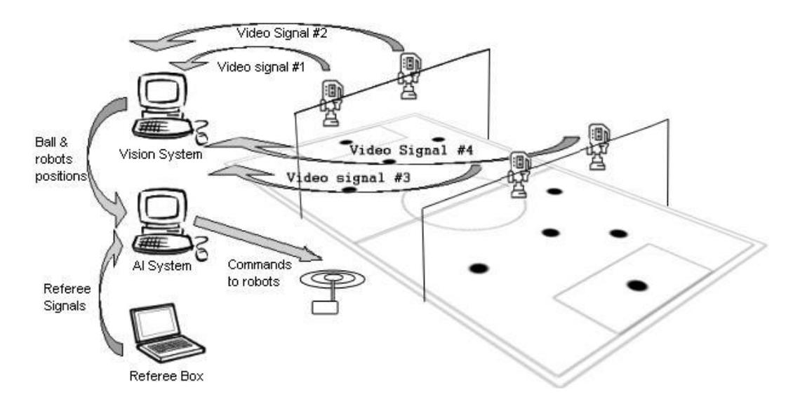
Vision
The vision system is the only source of feedback in the system architecture. If data returned by the vision system is inaccurate or incorrect, the overall performance of the team will be severely affected. Since a few years ago, SSL has a standardized and efficient vision system, which addresses this issue: the RoboCup Small Sized League Shared Vision System [3]. The official system for RoboCup SSL 2015 is implemented using four AVT Stingray F046C cameras mounted above a double-size field (8090mm x 6050mm).
To resolve the issue of false detection of robots near the edge of the field, i.e., when a robot with an ID pattern that is not actually in use is detected, we created a filter in our client that only adds robots to our game-model if they are detected for at least 25 frames out of 50 consecutive frames. This is unnecessary during a full game because the IDs of all participating robots are known and the system can be set to not include any other IDs, but allows flexibility during testing when we do not necessarily want to include all six robots in the game. False detection and addition of robots that are not on the field is significantly reduced.
Artificial Intelligence
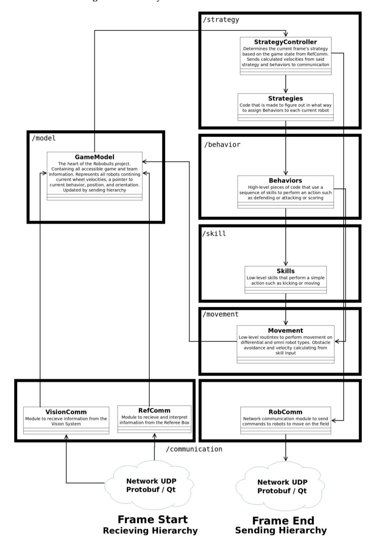
The RoboBulls 2015 software hierarchy is divided into many different independent modules. We will present an overview of our software modules and explain their connections to other parts of the project, in the order of high level to low level. The modules outlined here are Communication, GameModel, Strategy, Behavior, Skill, and Movement.
Communication
This module contains code for communication with all external sources. What we call VisionComm receives information from the vision system, RefComm from the referee box. RobComm is used to send our calculations to the robots.
First, VisionComm receives the standardized information of all objects on the field such as ID, X and Y coordinates, and orientation. At the same time, RefComm retrieves the state of the referee box. Currently, RefComm and VisionComm run on their own threads, and there is no synchronization. A single loop of the game is run when VisionComm receives and parses a new packet; all this information is read into our GameModel (See section 3.2) and a Strategy is chosen (See section 3.3).
The communication module is important because it needs to receive and report accurate information. To do so, we verify three main criteria for storing a detection frame. 1) That the reported SSL vision system tolerance is above a certain threshold. This is 0.8 for robots and 0.6 for the ball. 2) We check that the detection reported by the camera matches the correct object's position; with our current two-camera system, Camera 0 should report objects only with x < 0, and Camera 1 with objects only with x >= 0—we plan to extend our system to the full four-camera SSL vision system before the competition. 3) We only add detected robots to the system if they have been seen as a valid detection for at least 25 out of every 50 frames received.
GameModel
The GameModel is what we call the "heart of the system." It is so-called because it is a centralized location where all received information from communication is set. Then, the rest of the system operates off of the information contained in the GameModel. GameModel can be seen as a "cache" of the state of the real soccer field. Some information contained in the GameModel includes: the ball's position and velocity, individual robot's positions, IDs, and orientations (our team and the opponent team), the current game state, and others.
Strategy
We refer to Strategies as high-level pieces of code that coordinate assigning Behaviors. An analogy for a Strategy is a team coach on the side of the field shouting commands to players. The single active strategy is chosen by a StrategyController which takes the game mode input from the RefBox. Our system has one Strategy (method of assign robot-specific behaviors) for each ASCII state of the Referee Box. Strategies are implemented via polymorphism with two main functions--assignBeh() and update(). The former is run singly on receiving a new command; the latter is the continuously ran until a new Strategy is assigned.
Behavior and Skill
Once a Strategy is chosen by StrategyController, Behaviors are assigned to robots. A Behavior is an ordered set of skills that are performed to complete a high-level action—such as passing, scoring, moving, defending, or attacking. Typically implemented as a finite state machine, the Behavior is a member of the Robot class itself, and achieve functionality by using combinations of Skills. Skills are small singular actions such as kicking, turning, stopping, or dribbling. Because of their state-based construction, care must be taken to manage the robots' behaviors to keep their objects alive until they are finished—this is typically managed by StrategyController (mentioned in section 3.3). An important function of a Behavior is the perform() function, which defines action enacted on any generic robot it is assigned to. Skills and Behaviors achieve robot motion though interacting with the Movement module, as detailed below.
Movement
Movement is generally referred to the lowest level in the code hierarchy, and is mostly transparent to the user. It is a module containing omni and differential movement algorithms, obstacle avoidance, and robot collision resolution. Movement is centralized in that any movement on any robot is done through a base class called Move. Our system has been designed to run different types of robots, as it is also used to control differential and three-wheel holonomic robots, as explained in the Development section. In this way, the type of the robot is invisible to the user.
Obstacle avoidance is achieved using an obstacle avoidance algorithm designed for the SSL [2]. This approach divides a noisy path into multiple clear straightline segments, which are followed in a queue. To resolve collisions between robots, a sub-module called Movement Collisions keeps track of the distances and orientations of each robot. If robots are too close and are facing each other in a harmful manner, all movement calculation is ignored and negative velocities are sent to the wheels to move the robots backwards, and then plan a new path—this proves as an effective method for avoiding dangerous deadlock collisions.
Robots
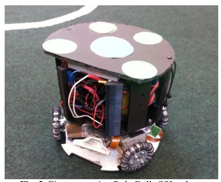
We are in the process of building a total of 6 robots with kickers and dribblers for RoboCup 2015. Prototypes of these robots have been already tested as shown in our qualification video. This section describes the current robot design and the pending changes planned for the competition. Figure 3 shows a first generation RoboBulls SSL robot. They are currently equipped with a kicker, but a dribbler implementation is in progress for the RoboCup 2015.
Hardware
The current robots are identical in their design. They have been constructed with custom aluminum plates and brackets made to firmly attach the motors. The motor system we use is a combination of brushless DC motors, spur gear-heads, and encoders encased together to minimize space. The motors are Maxon EC Flat 30 Watt brushless motors with a diameter of 42.9 mm. They have an idle speed of 4360 rpm and a maximum torque of 55mNm. The spur gear-heads, also from Maxon motors, have a 5:1 ratio and a 45mm diameter. The optical encoders, directly affixed to the back of the motor casing, generate signals at 1024 counts per turn.
The electrical components are organized in a housing compartment designed in SOLIDWORKS and printed by MakerBot 3D printers at USF facilities. This ensures our electrical components are safely positioned inside the robot. The major electrical components per robot are: 4 electronic speed controllers, 2 voltage regulators, 1 Arduino Mega 2560, 1 Wireless Arduino Shield, 1 Xbee module, 3.7V per cell lithium polymer batteries with two cells per pack totaling 7.4V per pack (5 packs per robot), and standard solder-less wires from components, motors, and solenoid. The large quantity of parts has led us to invest in a PCB board for the next generation of robots.
Motion
The motors are driven by electronic speed controllers (Sidewinder Micro) from Castle Creations. The inputs from the optical quadrature encoders are fed into an Arduino Mega 2560 microcontroller, which implements a proportional-integral (PI) control loop. The velocities from the motor encoders are mapped to the same scale as the Arduino PWM signals used to control the speed controllers, to make processing simpler.
Our initial approach to the PI (Proportional Integral) control was to set the control variable (the output PWM signal from the Arduino) equal to the PI term (Eq. 1). However, after extended calibration of the PI constants (kp and kI) using the Ziegler-Nichols methods [4], we were unable to create a controller that worked well at all speeds. For example, the controller would achieve the target motor velocity when the absolute velocity was less than 25% of maximum, but start to produce increasingly large steady state errors beyond this point. When tuned for higher speeds (higher than 30% of maximum), it produced sustained oscillations.
To achieve better control, we set the control variable equal to the set-point (our target speed) and then added the PI term (Eq. 2). To avoid large overshoots due to the increased maximum control input, the weighted PI sum was capped at 20% of the motor's maximum velocity (Eq. 3). After tuning kp and kI, this setup allowed for much better step response times with minimum over-shoot and is the currently used method of control.
Motor Velocity = $k_p \times P + k_I \times I$ (1)
Motor Velocity = Target Velocity + $k_p \times P + k_I \times I$ (2)
Max. Motor Speed $\times$ 0.2 $\leq$ $k_p \times P + k_I \times I \leq$ Max. Motor Speed $\times$ 0.2 (3)
Kicker
The kicker consists of a 24V push-pull solenoid mounted onto the base of the robot. A 5V relay controlled by the Arduino Mega acts as a switch, allowing it to send pulses (50 millisecond duration) of current to the solenoid to actuate a kick. This allows for a maximum kick range of approximately 5 meters. The software limits the kicker to 1 kick/second to prevent high currents from burning out the coil, and a spring mounted at the rear of the solenoid allows for it to be retracted once the signal sent to the relay from the microcontroller is turned off.
Serial Communication
Communication between the robots and the computer running the AI (Artificial Intelligence) is established using XBee radios at a baud rate of 57600bps. This rate is used to take advantage of the high throughput from the vision system which operates at over 50 fps, as higher update rates result in smoother motion with less over-shoot. Each packet has 6 such byte arrays for a packet size of 60 bytes. This allows 6 robots to be controlled simultaneously. Byte arrays begin and end with special marker characters as shown below to prevent the execution of corrupt commands:
Serial communication packet structure
| char(250) | ID | Wheel 1 | Wheel 2 | Wheel 3 | Wheel 4 | Kick | Unused | Dribble | char(255) |
|---|
Power
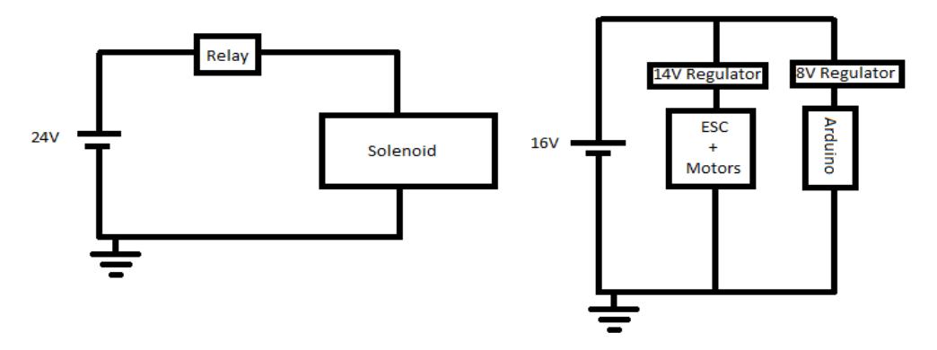
Each robot is powered by two packs of LiPo (Lithium Polymer) batteries, one 4 cell at 16V and another 6-cell at 24V. The 16V pack powers both the microcontroller and the motor-ESC (electronic speed controller) circuit. One parallel connection is regulated down to 8V for the Arduino Mega 2560 and another is regulated down to 14V for the motor-ESC circuit. The 24V battery powers only the solenoid and the circuit is switched on and off using a relay controlled by the Arduino. This is illustrated in Figure 4.
Planned improvements for RoboCup 2015
There are three major improvements planned for the competition:
Utilization of Hall-effect sensors: The Hall-effect sensors built into the motors are currently not utilized by the Castle Creations motor drivers, which leads to poor motor control at low velocities. This is due to a de-synchronization between the rotor flux and the stator flux. The Hall-effect sensors will allow us to read the position of the rotor so that the angle between the rotor flux and the stator flux can be kept as close to 90° as possible [5]. To achieve this, we plan to replace the Castle Creations Sidewinder Micro motor drivers with speed controllers from Maxon Motors (part number 336287) with Hall-sensor inputs.
Increased Kick Power: The current kicker does not kick the ball with enough force to propel it all the way down the new, larger field. The limited velocity of the ball also reduces an attacker's chance of scoring against a goalkeeper from reasonable distances. To increase the kicker power, we plan to increase the instantaneous current supplied to the solenoid when kicking by adding capacitors in parallel to the solenoid. If this should prove insufficient, we plan to use a DC converter to convert our 24V LiPo source for the kicker to a 100V source as outlined in the 2004 Electrical Team Documentation of the Cornell Big Red RoboCup team [6].
Dribbler: The current state of the SSL demands that robots be equipped with some form of ball control in order to move around with the ball and to maneuver it for passing and scoring. To this end, we plan to implement a dribbler to put a backward spin on the ball. This will be done with a rotating, rubber cylinder at the front of the robot actuated by a brushed DC motor.
Other planned changes include:
A dip-switch to change the robot's ID easily, which is currently hard-coded in the Arduino program.
Replacement of 3D printed interiors with aluminum to increase design flexibility and reduce cost and production time.
Design and fabrication of a durable outer casing to protect interior components during impact.
Development
In this section we describe our preliminary work testing our software with Lego robots prior to full SSL implementation, as well as some of the advantages and disadvantages of starting with Lego and migrating to SSL development.
One of the problems with starting software development for the SSL is that it is difficult to test until robots have been designed and assembled, and core hardware issues have been resolved. Open-source simulators such as grSim [7] mitigate this problem to an extent, but fail to simulate many aspects of the real world such as noise, false detections, poor lighting conditions, physical bias, communication errors, etc. Sources of error are also difficult to identify in a new system.
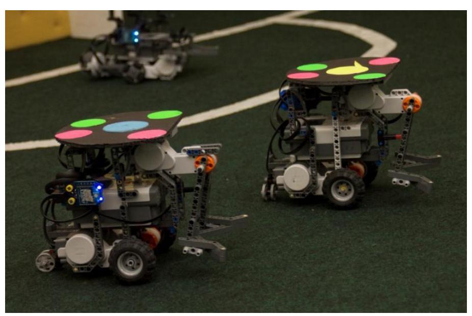
To speed up our development process, the software was initially tested with differential drive Lego NXT robots (Figure 5). This allowed us to move ahead in the software development process without being limited by the lack of functioning omni-drive robots. Our entire software architecture (strategies, behaviors, skills, and obstacle avoidance) was tested using the NXT robots and we were able to play 3 vs. 3 games moderated by Referee Box commands.
Research
Object tracking and prediction
Our current game model includes rudimentary algorithms for ball and robot position and velocity estimation. We intend to implement more sophisticated algorithms, such as the Kalman Filter [8] and particle filters [9]. Then, we plan to assess the suitability of each algorithm output to be used as an input to a stochastic planner [10]. Furthermore, we plan to review current extensions to those algorithms and evaluate them in the context of the SSL league. Finally, we plan to develop our own extension of the used algorithm to adapt it to our team needs.
Obstacle Avoidance
Our main obstacle avoidance algorithm is based on previous SSL league work [2]. We plan to develop on it, with a focus on a multi level obstacle avoidance system that is able to combine reactive behaviors with high level trajectory plans.
Point-based POMDP planners
We intend to extend our current system for strategy design using partially observable Markov decision process planers [11]. We plan to include a model of how each behavior modifies the current state of the game and perform an approximate search on the possible behavior assignment to each robot of the team.
Conclusion
We presented a software and hardware overview of the SSL RoboBulls team. The omni-directional motion control and obstacle avoidance have been described in detail.
We have developed a working prototype for our SSL 2015 team. Omnidirectional robots are controlled, showing proper motions, ball handling and interaction. The control software has been developed and tested in full games using prototype robots in addition to using the grSim [7] simulator. The control software was later adapted to the omni-directional, first generation robots successfully. All layers involved in the processing of one vision frame; namely network communications, world modeling, high-level strategies, low-level behaviors and skills, communication, kicking and motor control have been implemented, tested and shown to work.
Short-term future work consists of improving the current robots for the 2015 competition, including implementing a hall-sensor based motor control, a stronger kicker and a dribbler.
Medium and long-term future work will consist of research on stochastic estimation, planning under uncertainty, applied bio-inspired navigational models and obstacle avoidance algorithms, and the application of the outcome of this research to the robot control software.
More information can be found at: www.usfrobobulls.org
Our Qualification Video can be found at: https://www.youtube.com/watch?v=cbX74rGz1xY
Acknowledgements
This work is supported in part by the USF Student Government, the Bio-Robotics Lab at USF and the NSF grant #1117303 entitled "Investigations of the Role of Dorsal versus Ventral Place and Grid Cells during Multi-Scale Spatial Navigation in Rats and Robots,". We would like deeply thank Juan Calderon and the STOx's small size league team of Santo Tomas University for their help and advice.
References
- "Home RoboCup 2015 Hefei China." [Online]. Available: http://www.robocup2015.org/. [Accessed: 05-Mar-2015].
- S. Rodriguez, E. Rojas, K. Perez, J. L. Jimenez, C. Quintero, and J. Calderón, "Fast Path Planning Algorithm for the RoboCup Small Size League," 2014.
- Zickler, Stefan, et al. "SSL-vision: The shared vision system for the RoboCup Small Size League." RoboCup 2009: Robot Soccer World Cup XIII. Springer Berlin Heidelberg, 2010. 425-436.
- Hang, Chang C., Karl Johan Åström, and Weng Khuen Ho. "Refinements of the Ziegler–Nichols tuning formula." IEE Proceedings D (Control Theory and Applications). Vol. 138. No. 2. IET Digital Library, 1991.
- Gamazo-Real, José Carlos, Ernesto Vázquez-Sánchez, and Jaime Gómez-Gil. "Position and speed control of brushless DC motors using sensorless techniques and application trends." Sensors 10.7 (2010): 6901-6947.
- Ahlawat, Pranay, Cliff Gaw, Joseph Golden, Karan Khera, Anthony Marino, Mike McCabe, Aaron Nathan, and Nathan Pagel. "Robocup Systems Engineering Project 2004." Cornell Robocup - Documentation. Cornell University, 5 Dec. 2004. Web. 09 Mar. 2015.
- Monajjemi, Valiallah, Ali Koochakzadeh, and Saeed Shiry Ghidary. "grsim– robocup small size robot soccer simulator." RoboCup 2011: Robot Soccer World Cup XV. Springer Berlin Heidelberg, 2012. 450-460.
- G. Welch and G. Bishop, "An Introduction to the Kalman Filter," University of North Carolina at Chapel Hill, Chapel Hill, NC, USA, 1995.
- R. E. Kalman, "A New Approach to Linear Filtering and Prediction Problems," Trans. ASME–Journal Basic Eng., vol. 82, no. Series D, pp. 35–45, 1960.
- S. Thrun, W. Burgard, and D. Fox, Probabilistic Robotics. The MIT Press, 2005.
- H. Kurniawati, Y. Du, D. Hsu, and W. S. Lee, "Motion Planning under Uncertainty for Robotic Tasks with Long Time Horizons," in Robotics Research, C. Pradalier, R. Siegwart, and G. Hirzinger, Eds. Springer Berlin Heidelberg, 2011, pp. 151–168.