RoboDragons 2015 Extended Team Description
Yusuke Adachi, Hiroyuki Kusakabe, Yuya Yamanaka, Masahide Ito, Kazuhito Murakami, Tadashi Naruse
School of Information Science and Technology, Aichi Prefectural University
http://www.ist.aichi-pu.ac.jp/lab/narulab/index.html
Abstract This paper describes a system configuration of RoboDragons 2015, Aichi Prefectural University's participating team for the Small Size League of RoboCup Soccer. On the robot hardware, we basically use the robots developed in 2012. We changed the radio system from the 2.4 GHz band to the 5 GHz band, and also adjusted the chip-kick board so as to improve stability in keeping the ball. On the software system, the base part has been developed by CMRoboDragons joint team in 2004 and 2005. After the end of the joint team, we are continuously improving the software system by introducing our research results. We describe two algorithms in this paper. One is a dynamic ball kicking algorithm which is often used in offensive strategies; Another is a circle-and-pass motion algorithm which is used on throw-in. The effectiveness of these hardware and software improvements is experimentally shown.
Introduction
RoboDragons 2015 is the team of Aichi Prefectural University participating in the Small Size League (SSL) of RoboCup Soccer. The activity started in 1997 as a joint team Owaribito with Chubu University. In 2002, as each University had been able to develop their robot system independently, we started a new team, RoboDragons. Since then, RoboDragons participate in SSL every year, including the joint team CMRoboDragons (2004–2005) with Carnegie Mellon University. Our best record is the 2nd place in 2009. Other than that, two third places (2007 and 2014) and three fourth places (2004, 2005, and 2013).
This paper describes a system configuration of RoboDragons 2015. We basically use the sixth generation robots developed in 2012, but two minor changes on the robot hardware were performed in 2014 and 2015. The first change is that the 5 GHz wireless LAN module instead of the 2.4 GHz one was adopted in order to avoid frequency interference; the second change is that the mechanical design of the chip-kick board was adjusted so as to improve stability in driblling/trapping the ball. On the other hand, based on our software system which has been developed by CMRoboDragons joint team in 2004 and 2005, we are continuously improving it by introducing our research results. In this paper, a dynamic ball kicking — a robot runs after the ball as turning its face toward the target direction and kicks the ball —, and a circle-and-pass motion — the robot can quickly change its kick direction by going around the ball on throw-in for disturbing the opponents — are shown. The effectiveness of the improvements is experimentally demonstrated.
Robot Hardware
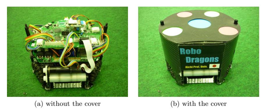
In this year, RoboDragons use the sixth generation robots, whose major part has been developed in 2012. The robot shown in Fig. 1 has features as follows:
- Cylinder with dimensions of 125 mm height and 178 mm diameter,
- Weight: 2.3 kg,
- Maximum percentage of the ball coverage: about 18%,
- Motor: 50 watt DC brushless motor for driving a wheel,
Device Description Control Unit CPU: SH2A processor (Renesas Electronics Corporation) operated with 196 MHz clock. Peripheral circuits (except analog circuits) are almost in the Xilinx's Spartan-6 FPGA. Boost Converter Convert from 18.5 V DC to 150 V - 200 V DC. Condenser has a capacity of 4400 μF. Charging time is about 2 s (when output voltage is 200 V). Motor Maxon "EC 45 flat 50W". Gear reduction ratio between motor and omni-wheel is 21:64. Wheel 4 omni-wheels, each has 20 small tires in circumference. Diameter: omni-wheel 55 mm, small tire 12.4 mm. Dribble Device Dribble roller: 16 mm in diameter and 73 mm in length, made of aluminum shaft with silicon rubber. Motor is Maxon "EC 16 30W". Ball Sensor Infra-red light emission diode and photo diode pair. Kicker Kick bar is made of 7075 aluminum alloy. Solenoid is a coil winding ϕ 0.6 mm enameled wire. Straight kicker kicks a ball with over 8 m/s velocity at maximum. Chip-kicker kicks a ball as far as 4 m distance at maximum. Communication IEEE 802.11abgn 2.4/5 GHz wireless LAN.
Summary of the robots
| Device | Description |
|---|---|
| Control Unit | CPU: SH2A processor (Renesas Electronics Corporation) operated with 196 MHz clock. Peripheral circuits (except analog circuits) are almost in the Xilinx's Spartan-6 FPGA. |
| Boost Converter | Convert from 18.5 V DC to 150 V - 200 V DC. Condenser has a capacity of 4400 μF. Charging time is about 2 s (when output voltage is 200 V). |
| Motor | Maxon "EC 45 flat 50W". Gear reduction ratio between motor and omni-wheel is 21:64. |
| Wheel | 4 omni-wheels, each has 20 small tires in circumference. Diameter: omni-wheel 55 mm, small tire 12.4 mm. |
| Dribble Device | Dribble roller: 16 mm in diameter and 73 mm in length, made of aluminum shaft with silicon rubber. Motor is Maxon "EC 16 30W". |
| Ball Sensor | Infra-red light emission diode and photo diode pair. |
| Kicker | Kick bar is made of 7075 aluminum alloy. Solenoid is a coil winding ϕ 0.6 mm enameled wire. Straight kicker kicks a ball with over 8 m/s velocity at maximum. Chip-kicker kicks a ball as far as 4 m distance at maximum. |
| Communication | IEEE 802.11abgn 2.4/5 GHz wireless LAN. |
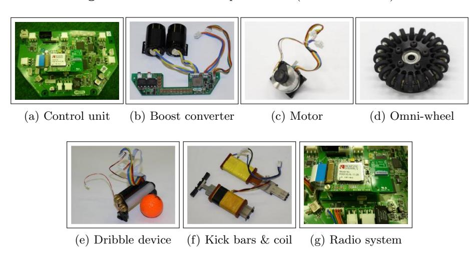
Each component of the robot is summarized in Table 1, and its photos are presented in Fig. 2. In the following subsections, we focus on two minor changes on the robot hardware.
Improvement of Radio System
In the early design of the sixth generation robot, we used 2.4 GHz wireless LAN for communication between the robots and a host computer, and it worked well in RoboCup Japan Open 2013. However, in RoboCup 2013, the interference was induced since several leagues shared a hall and a radio system in the hall also used the same wireless LAN. Therefore, we changed the radio system from the 2.4 GHz band to the 5 GHz band just before RoboCup 2014. As a new radio module on the robot, we adopted a Redpine Signals RS9110-N-11-28 shown in Fig. 2 (g). In fact, we confirmed that wireless communication worked very well in RoboCup 2014.
Improvement around Dribble Device
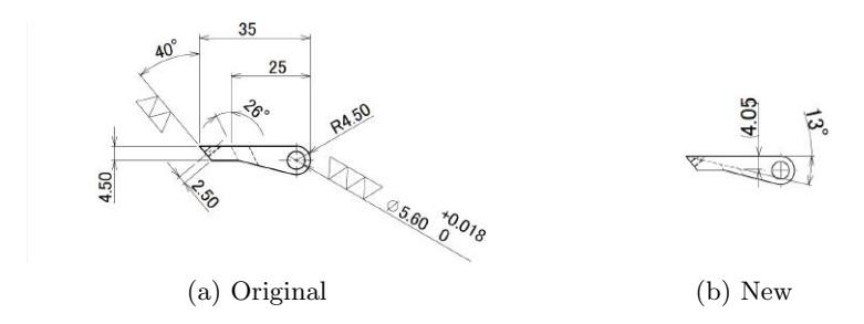
The robot had a problem in keeping a ball. That means it is unstable for the dribble device to dribble/trap the ball. After much trial and error, we found that the stability is improved by adjusting the mechanical design of the chipkick board. Finally, we made the position of the dribble roller 1 mm higher and the chip-kick board 0.45 mm thinner (the latter work is as shown in Fig. 3).
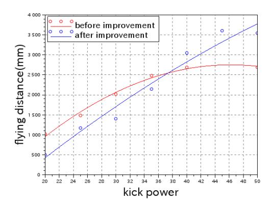
This work contributed not only stabilization of keeping the ball but also improvement of the flying distance by chip-kicking. Figure 4 shows experimental results with respect to the flying distance by chip-kicking. It is clear that the improved chip kicker can fly the ball further away.
Dynamic Ball Kicking
One of the useful attacking skills is that a running robot kicks a moving ball. It will be often used when a robot runs after the ball as turning its face toward the target direction and kicks the ball.
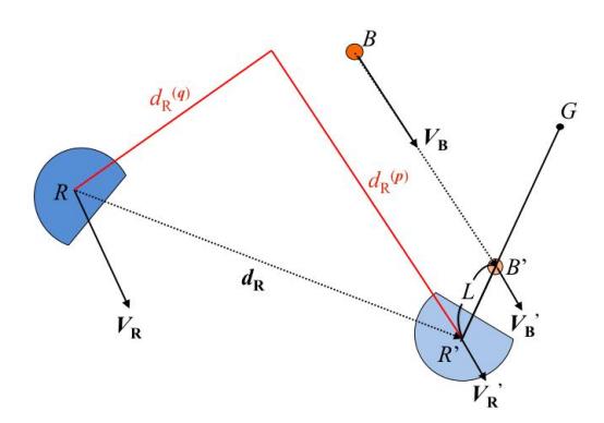
Table 2 summaries the symbols used in this section. A typical situation is represented in Fig. 5, where the symbols are listed in Table 2. A Robot R runs after the ball B and then comes to R′ as turning its face toward target position G. At the time, a ball B reaches B′.
For the sake of simplicity, the following assumptions are introduced in this section:
Symbols list
| Symbol | Definition |
|---|---|
| $\overline{B,B'}$ | coordinate of the ball |
| R, R' | coordinate of the robot |
| $\boldsymbol{V}_B, \boldsymbol{V}_B'$ | velocity vector of the ball |
| $\boldsymbol{V}_R, \boldsymbol{V}_R'$ | velocity vector of the robot |
| G | target position |
| L | offset length |
| $\boldsymbol{p}$ | the unit vector in the direction of $\boldsymbol{V}_B$ |
| $\boldsymbol{q}$ | the unit vector which is orthogonal to p, i.e., p ⊥ q |
| $\boldsymbol{d}_R$ | vector from $R$ to $R'$ |
| $\boldsymbol{d}_R^{(p)} \boldsymbol{d}_R^{(q)}$ | component of vector $\boldsymbol{d}_R$ in the direction of $\boldsymbol{p}$ |
| $\boldsymbol{d}_R^{(q)}$ | $=\boldsymbol{d}_R-\boldsymbol{d}_R^{(p)}$ |
| $D_B$ | ball deceleration due to the friction |
| $V_{\rm max}$ | maximum velocity of the robot |
| $A_R$ | maximum acceleration of the robot |
| $D_R$ | maximum deceleration of the robot |
- There does not exist any obstacles in the field.
- The ball does not get any force except for friction force.
- Any robot motion is within the field.
- The parameter $D_B$ is constant.
From the geometric relation as shown in Fig. 5, if the robot takes T seconds to move from R to R', then the velocity vector of the ball $V'_B$ and the coordinate of the ball B' can be expressed as follows:
$$V'_B = V_B - D_B T \frac{V_B}{|V_B|}$$
and
$$B' = \frac{1}{2} (|V_B| + |V'_B|) T + B.$$
(1)
Now, by using Eqs. (1), design a motion profile so as to achieve dynamic ball kicking. First, decompose the robot velocity vector, $V_R$, into two components in the direction of $\boldsymbol{p}$ and $\boldsymbol{q}$, i.e., $\boldsymbol{V}_R^{(p)} = \boldsymbol{V}_R \cos \alpha$ and $\boldsymbol{V}_R^{(q)} = \boldsymbol{V}_R \sin \alpha$, where $\alpha$ is an angle of $\boldsymbol{V}_R$ with respect to $\boldsymbol{p}$. Then, at R', if we can control the velocity $\boldsymbol{V}_R'$ to be $\boldsymbol{V}_R'^{(p)} = \boldsymbol{V}_B'$ and $\boldsymbol{V}_R'^{(q)} = 0$, the robot can easily kick the ball by approaching the ball.
If $A_R$ and $D_R$ are given, we can calculate the ball position B' by Eq. (1). Then, we can make a motion profile of the robot for $V_R^{(p)}$ and $V_R^{(q)}$, respectively, because we can calculate R', $d_R$, $d_R^{(p)}$, and $d_R^{(q)}$. On the contrary, if the motion profile of the robot for a direction p is made, we can calculate T. By iterating this process, we can make the motion profiles realizing the run-kick skill shown in Fig. 5.
Design of a motion profile for the velocity $V_{\scriptscriptstyle R}^{(p)}$
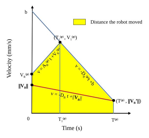
For a given T, we can design a motion profile as shown in Fig. 6. Assume $A_R^{(p)} = A_R \cos \beta$ and $D_R^{(p)} = D_R \cos \beta$, where $\beta$ is a parameter for decomposition of desired velocity and acceleration/deceleration. In Fig. 6, variables $b^{(p)}$, $(T_1^{(p)}, V_1^{(p)})$, and $d^{(p)}$ can be calculated by the following equations:
$$\begin{split} b^{(p)} &= | \boldsymbol{V}_B' | + D_R T^{(p)}, \ (T_1^{(p)}, \ V_1^{(p)}) &= \left( \frac{b^{(p)} - V_R^{(p)}}{D_R + A_R}, \ A_R T_1 + V_R^{(p)} \right), \ d^{(p)} &= \frac{1}{2} { (V_R^{(p)} + V_1^{(p)}) T_1^{(p)} + (V_1^{(p)} + | \boldsymbol{V}_B' |) (T^{(p)} - T_1^{(p)}) }. \end{split}$$
In motion profile, since the yellow area in Fig. 6 means a planned travel distance $d^{(p)}$ of the robot in the direction of p. Therefore, if $d^{(p)} \approx ||d_R^{(p)}||$, we can obtain the desired motion profile with the final $V_R^{\prime(p)}$ being equal to $||V_B^{\prime}||$ at $R^{\prime}$. Then, how can we calculate $T^{(p)}$? Bisection or Newton method [5]. The initial value of T is, for instance, the time when the ball is just stopped by the constant ball deceleration $D_B$. The parameter $\beta$ can be determined by the same way.
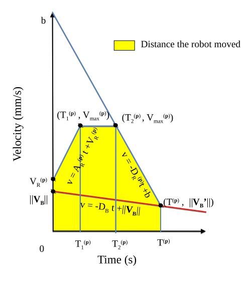
In case of $V_1^{(p)} > V_{\text{max}} \cos \beta$, we make a motion profile as shown in Fig. 7. In this figure, variables $b^{(p)}$, $T_1^{(p)}$, $T_2^{(p)}$, $T_2^{(p)}$, and $d^{(p)}$ are calculated as follows:
$$\begin{split} b^{(p)} &= |\boldsymbol{V}{B}^{(p)}| + D{R}^{(p)}T^{(p)}, \ T_{1}^{(p)} &= \frac{V_{\max}^{(p)} - V_{R}^{(p)}}{A_{R}^{(p)}}, \ T_{2}^{(p)} &= \frac{b^{(p)} - V_{\max}^{(p)}}{D_{R}^{(p)}} - T_{1}^{(p)}, \ T^{(p)} &= T^{(p)} - (T_{1}^{(p)} + T_{2}^{(p)}), \ d^{(p)} &= V_{\max}^{(p)}T^{(p)} - \frac{1}{2} { \ (V_{\max}^{(p)} - V_{R}^{(p)})T_{1}^{(p)} + (V_{\max}^{(p)} - |\boldsymbol{V'}_{B}^{(p)}|)T^{(p)} \ }. \end{split}$$
Design of a motion profile for the velocity $V_R^{(q)}$
By the method discussed in section 3.1, we can get the value of T. With this T, we can calculate the position R' and hence $d_R^{(q)}$. Therefore, we can make a motion profile for $V_R^{(q)}$. In this motion profile, the velocity at R' is equal to 0. In the calculation of the motion profile, we use $A_R$, $D_R$ and $V'_{\text{max}}$ that are defined in section 3.1.
From the two motion profiles, a velocity vector $V_R$ is produced, i.e., $V_R(t) = V_R^{(p)}(t) p + V_R^{(q)}(t) q$.
Angular velocity is also calculated so that the front of the robot face rotates to face the target position G. In our system, constant angular velocity is adopted.
Circle-and-Pass Skill on Throw-in
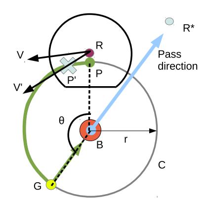
So far, we have used the Rapid Random Tree (RRT) algorithm for path planning [4]. On throw-in, however, an easy and opponents disturbing path planning is welcomed in order to improve the success rate of passing between teammate robots. We have designed a new skill named circle-and-pass as shown in Fig. 8. This skill starts when the robot gets in the circle with a radius of $r + \alpha$ and center at the ball. We assume that the front of the robot faces the ball when it gets in the circle. In this skill, the kicker first goes around the ball with its front facing the ball and then kicks the ball. As a result, the robot can easily kick the ball toward the desired direction and the opponent robots will be disturbed by the quick change of the kicking direction of the kick robot. In the next section, we give the algorithm.
Algorithm
We describe the circle-and-pass algorithm. First, we define symbols used in the algorithm.
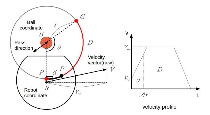
Let B, R, and R* be the positions of the ball, the kicker robot and the target robot, respectively. Consider a circular path C around B with radius r. Let P be the intersection of C and the line segment BR and let G be the intersection of C and the line segment $\overline{BR*}$. $d_m$ means the max decleration of the robot. Furthermore, let D and $\theta$ be the length and angle of the arc PG, respectively. In the following, a frame period $\Delta t$ means 1/60 seconds and "an angle is small enough" means the angle is less than an appropriate threshold (which will be determined by the experiment).
Algorithm 1 (Circle-and-Pass Skill).
- Step 1. Move the robot R along the arc PG with its front facing the ball B. If the robot is close enough to G and the angle between the pass direction vector and the forward direction vector of the robot is small enough for three consecutive frame periods, then the robot changes the moving direction and moves toward the ball and kicks the ball.
- Step 2. For present velocity vector V, calculate a tangential component vector to the circle. Let it be $V_0$ and let $v_0$ be $||V_0||$. If $v_0$ is less than $||V|| d_m \Delta t$, let $v_0$ be $||V|| d_m \Delta t$ in order to avoid uncontrolled situation.
- Step 3. Make a velocity profile on the arc PG with the initial velocity $v_0$. From the velocity profile, calculate the move distance d on the arc PG after $\Delta t$ (see Figs. 9 and 10). Let it be P'.
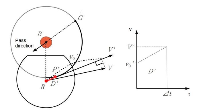
- Step 4. Let the length of the line segment $\overline{RP'}$ be D' and let the $\overline{RP'}$ direction component of the vector $\mathbf{V}$ be $\mathbf{V}'$ and its size be $v_0'$. If $v_0'$ is less than $|\mathbf{V}| d_m \Delta t$, let $v_0'$ be $|\mathbf{V}| d_m \Delta t$.
- Step 5. Calculate an acceleration a to move D' mm in $\Delta t$ second with an initial speed $v'_0$. As the right of Fig. 10, calculate V' from a trapezoid. Next, calculate a from $(V' v'_0)/\Delta t$.
$$D' = \frac{1}{2}(v'_0 + V')\Delta t$$
$$V' = \frac{2D'}{\Delta t} - v'_0$$
$$a = \frac{1}{\Delta t}(V' - v'_0)$$
$$a = 2\left(\frac{D'}{\Delta t^2} - \frac{v'_0}{\Delta t}\right)$$
If a is greater than the maximum acceleration or maximum deceleration, a is truncated.
- Step 6. Calculate the velocity $v_1$ at the time when the robot arrived at P' and let $V'_{\text{new}} = v_1 V' / ||V'||$.
- Step 7. With the velocity $V'_{\text{new}}$, the robot is moved. Then, go to step 1.
Comparisons
We compared the circle-and-pass algorithm with the conventional algorithm based on RRT.
For the initial angle values of 130 degree and 160 degree, which are occurred often on throw-in, we carried out the experiments for each algorithm. The robot start at 119 mm away from the ball at first, then 129 mm away ... up to 189 mm away (every 10 mm). In the circle-and-pass motion, the radius r is equal to the distance from the ball to the start position. The values shown in the table are the best values in the experiments, for example, for rotation angle 130 degree, robot start at 119 mm away from the ball brought the best result for the circle-and-pass algorithm.
From the table, new algorithm shows the better performance than the traditional one.
Comparison of circle-and-pass (C&P) and RRT-based algorithms
| Rotation angle: θ | 130° | 160° | ||
|---|---|---|---|---|
| Algorithm | C&P | RRT | C&P | RRT |
| Initial distance betw. R & B (mm) | 119 | 149 | 119 | 149 |
| Necessary time (s) | 1.12 | 1.19 | 1.24 | 1.63 |
| Moving distance (mm) | 432 | 485 | 498 | 797 |
| Maximum distance from ball (mm) | 126 | 194 | 129 | 277 |
| Error angle of pass direction (rad) | 0.020 | 0.023 | 0.024 | 0.029 |
Concluding Remarks
We have shown the RoboDragons system's hardware and software configuration, and useful algorithms in this paper. The robots are introduced in 2012 and improved every year. Major changes are the radio module in 2014 and the chipkick board in 2015. In soccer program, we have developed a basic skill that a running robot kicks a moving ball in 2012. Using this skill, we developed many skills such as a run-pass, a run shoot, a star passing (for demo) and so on. In this paper, we show a revised description of the basic skill, which initial version was shown in 2012 ETDP. A circle-and-pass motion algorithm has been using since 2013. However, we haven't shown it yet, we showed the detailed description of the algorithm this year.
References
- Ishikawa, A., Sakai, T., Nagai, J., Inagaki, T., Sawaguchi, H., Nunome, Y., Murakami, K., Naruse, T.: RoboDragons 2010 Team Description. RoboCup 2010 Symposium CD-ROM (2010)
- Yasui, K., Inagaki, T., Sawaguchi, H., Nunome, Y., Sasai, H., Tsunoda, Y., Matsuoka, S., Kawajiri, N., Sato, T., Murakami, K., Naruse, T.: RoboDragons 2012 Team Description. RoboCup 2012 Symposium CD-ROM (2012)
- Yasui, K., Nunome, Y., Matsuoka, S., Adachi, Y., Atomi, K., Ito, M., Kobayashi, K., Murakami, K., Naruse, T.: RoboDragons 2013 Team Description. RoboCup 2013 Symposium CD-ROM (2013)
- Bruce, J., Veloso, M.: Real-time randomized path planning for robot navigation. IEEE/RSJ Int. Conf. on Intelligent Robots and Systems, 3, 2383–2388 (2002)
- Newton's Method. http://www.math.montana.edu/frankw/ccp/calculus/numerical/newton/learn.htm