RoboJackets 2015 Team Description Paper
Matthew Barulic, Justin Buchanan, Boris Iachonkov, Emanuel Jones, Jonathan Jones, Ahmed Mansour, Ryo Osawa, Ryan Strat
Georgia Institute of Technology
Abstract The RoboJackets RoboCup SSL team was founded in 2007 and has competed every year since. The main focus this year was taking the lessons learned from our previous fleet of robots to design and build an entirely new one. Areas of focus for the new robot design include: a damped dribbler, more powerful motors, and increased robustness and modularity of electronics. This paper outlines the improvements that we have made in the new fleet's design and the as well as improvements in software.
1 Mechanical
For RoboCup 2015, the mechanical base of the RoboJackets robot fleet was completely redesigned. The major goals for the mechanical team were to design a more robust drivetrain, incorporate a damped dribbler, and develop a compact flat solenoid. The team also emphasized creating designs which stress ease of manufacturing to expedite the production of a new robot fleet.
1.1 Drivetrain
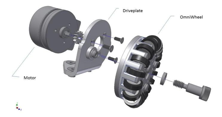
The drivetrain consists of three major components: the motor, the drivetrain mount, and the omnidirectional wheel, all of which can be seen in Figure 1.
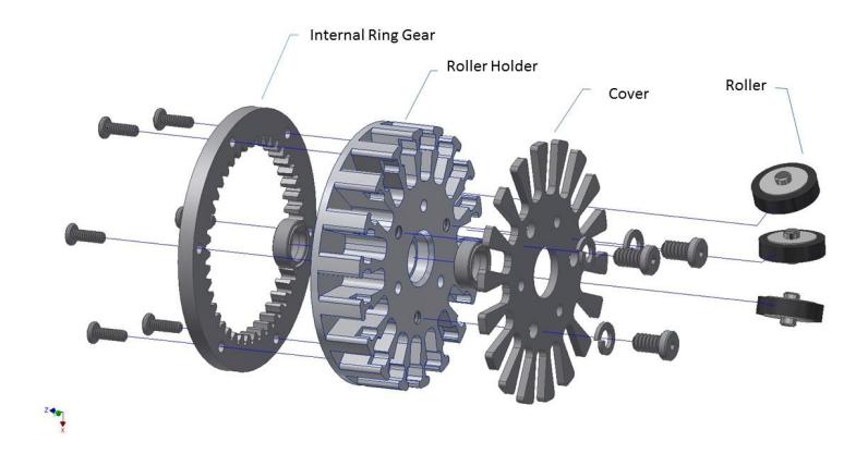
The 2015 drivetrain contains elements from the previous two generations of robots: the 2008 and 2011 fleets. The drive gears are similar to the compact, internal ring gear design from the 2011 fleet. The drivetrain mounts are also fixed to the robot chassis in a manner similar to the 2008 fleet. The motors, however, have been upgraded from 30W to 50W, which allows the robots to achieve higher acceleration and better control.
Motors and Drive Gears The motors used on the robots are brushless DC 50W Maxon Motors (PN: 3392825x), each with a MILE Encoder (PN: 462003x) integrated into the motor. Moving from the lower power 30W improved robot mobility. These motors are larger and require more effort to integrate them into the robot, however the encoders are integrated and otherwise would have been added separately. The motors are custom ordered to have shorter shafts with a flat section to constrain a small spur gear.
1.2 Chipper and Kicker
In the 2015 fleet, the chipper and kicker both utilize a custom-made flat solenoid in order to minimize space consumption. The chipper was also designed to provide a second point of contact on the ball when dribbling.
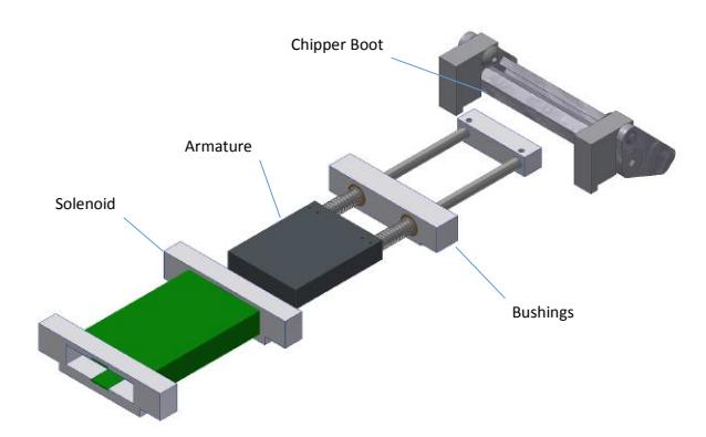
Solenoids A critical difference in the 2015 fleet as compared to the 2011 and 2008 fleets are custom-made rectangular solenoids. These solenoids were used in both the kicker and chipper assemblies. The main advantage of these solenoids is that they take less space than cylindrical solenoids. The rectangular solenoid consists of a 3D printed ABS plastic center with two aluminum faces. The new solenoids were tested against the cylindrical ones used in the older fleet. It was determined that the momentum produced by the new solenoids is on average 5% greater than the old solenoids. In an effort to improve performance, a study on casing was conducted. Silicon steel was extracted from old transformers and formed into a shell around the solenoid. It was calculated that the performance increased by 2.47% when only one sheet of 1/32" thick silicon steel was used [1, RC15-FlatSolenoid]. It should also be noted that these silicon steel sheets have anisotropic properties. This is important because the orientation of individual sheets may change the effectiveness of the flux return path. Finally, the armature of the solenoid was based on a mass-momentum study which concluded that the theoretical highest efficiency is achieved by having the mass of the armature be equal to the mass of the ball (46 g). Figure 5 shows the solenoid and the chipper assembly.
1.3 Dribbler
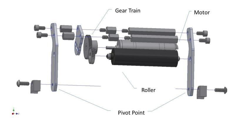
The dribbler assembly has been improved for easier manufacturing and better performance. The manufacturing was improved by designing parts that can be easily cut on the water jet cutter. Figure 6 shows the breakdown of the design. The functionality improvements of the dribbler assembly consist of a wider mouth and a damping feature. The mouth increased from 2.3" to 2.6" wide, which allows the ball to be received from a greater angle and requires less precision on the side of software. The function of the damping assembly is to reduce "bounce back," allowing ball settling to be quicker. The damping is created by a foam-spring combination mounted behind the dribbler, producing an almost critically damped system.
2 Electrical
2015 marks a complete restructuring of the electrical subsystem of the robot. The new design takes a modular approach for enhancing maintainability and extendibility. The 2015 electrical subsystem is a modular system that consists of a control board, a kicker board, a motor board, a radio board, and an mbed microcontroller. All electrical boards connect with the control board, which routes logic signals between the mbed and peripheral boards. In order to make such a system financially feasible, all boards are panelized prior to production and are laser cut to the desired dimensions in-house.
2.1 Control Circuitry
The 2015 control board is a stripped-down version of the 2011 RoboJackets control board. This year, the Atmel SAM7S series microcontroller (AT91SAM7S256) and its corresponding USB interface were replaced with ARM's mbed platform featuring an NXP LPC1768 microcontroller that uses a Cortex-M3 processor. Improvements found in the mbed over the previous Atmel chip include support for standardized thread-based multitasking and a C++ SDK. Additionally, the mbed Cookbook features a large collection of community-maintained software libraries for common components and interfaces that are used in the 2015 electrical system. The mbed plugs directly into the control board for easy removal of the device.
The control board retains Xilinx's Spartan-3E FPGA used in previous versions of the control board. The FPGA communicates with the mbed via an SPI bus and is responsible for low-level motor controls and encoder tick counting. Since the encoders used on the 2011 robots supplied a single-ended signal, the FPGA's control subsystem was updated this year to support the differential signal from the updated encoders. This is achieved using an EIA-422 receiver for the incoming differential signals from the encoders.
With the league's field size expansion and the resulting drive motor upgrade, a new battery was needed for providing a higher voltage to the motors. The previous 4-cell lithium polymer batteries were replaced with 5-cell ones to increase the system's nominal voltage from 14.8V to 18.5V. The power distribution circuitry was changed to accommodate the robot's higher input voltage.
The new control board features an improved hardware status feedback interface, which consists of LEDs placed in close proximity to each circuit subsection. Should the firmware detect a hardware error, the corresponding LED will be illuminated. The mbed interfaces with the LEDs via an I/O expander.
2.2 Motor Driver Circuitry
As was mentioned in the Drivetrain section of this document, the 2015 fleet uses new 50W 3-phase brushless motors from Maxon. This is in contrast to the 30W models used on the 2008 and 2011 fleets. As such, the motor driving circuit has been redesigned to handle the power increase. All drive motor circuits have been migrated to a separate board to allow design flexibility. This change reduces cost for any minor changes in any of the subsystems. Furthermore, this setup allows for a more intuitive debug process through the use of the board-to-board connectors.
The updated 3-phase driver circuit retains the dual n-FETs discussed in last year's RoboJackets TDP [5], but it also introduces TI's DRV8302 that replaces the three FET drivers, which were used to drive each phase individually. The DRV8302 also features over-current, over-voltage, under-voltage, thermal, and shoot through protection. This is expected to greatly reduce damage to the FETs that was common on the 2011 control boards.
2.3 Kicker Circuitry
The 2011 design used two 2700µF aluminum can electrolytic capacitors to store the electrical energy. Mounting large capacitors vertically made maintenance of the boards very difficult. In the 2013 design phase, the two large capacitors were replaced with three 820µF capacitors and mounted in the plane of the board. For the 2015 design, the kicker board was required to have a reduced size to provide room for the larger motors. Directly mounting capacitors on the kicker board requires excess board space due to mechanical constraints. Short wires were thus used to connect the capacitors to the board without significantly increasing the resistance and inductance between the source (capacitor bank) and load (solenoid).
Lastly, in order to improve kicker functionality and safety, we are adding an Atmel ATtiny microcontroller to the kicker board. In the 2011 kicker board the two ways to discharge the energy stored in the capacitors were to fire the solenoid or slowly dissipate the energy through a set of bleeder resistors. Having a microcontroller on the kicker board allows for improved safety logic when there is no active connection with the mbed. The ATtiny will communicate with the mbed via SPI. Initially, this will be used to receive control commands and report the charge level to the mbed. However, in the future, it will be possible to greatly enhance data collection via firmware upgrades.
2.4 Radio Circuitry
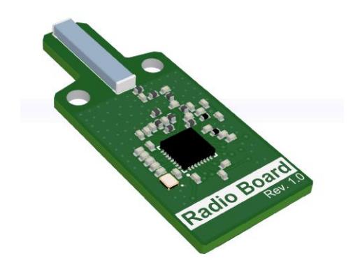
In the 2015 revision, radio hardware is sectioned out to a separate board, which is directly attached to the control board over an SPI connection. The new radio board features a chip antenna that replaces the large halo antenna used previously and is shown in Figure 7. Chip antenna technology has advanced since the halo antennas were manufactured in 2008, so an improved selection of chip antennas can be found today [4]. A similar radiation pattern is achieved using the much smaller footprint. Since few obstacles exist at the physical layer for the application of the Small-Size League, no drops in system performance are expected.
The radio's central component that is paired with the chip antenna is TI's CC1201 transceiver. It is an updated version of the CC1101 that provides support for 4-GFSK modulation to increase communication rates over currently used 2- GFSK modulation. The transceiver will be paired with a dual-antenna base station.
3 Software
The major software focus over the last year has been redesigning and rewriting the high-level code responsible for gameplay.
3.1 Previous Gameplay System
The previous gameplay implementation was written in C++ and based on the Skill Tactic Play (STP) paradigm, as described in [2]. STP is a gameplay architecture that involves splitting up behaviors into three main categories: skills, tactics, and plays. Skills are low-level behaviors that use a single robot, such as capturing the ball, kicking the ball, and marking an opponent player. Tactics are higher-level than skills and often involve coordinating behavior among two or more robots. Example tactics include passing and coordinated defense. Plays are behaviors that describe the behavior of the entire team of robots. They rely on skills and tactics to do most of their work and are mainly responsible for the coordination between the different sub-behaviors.
The STP architecture is effective because it encourages high code re-use and provides a framework for organizing high-level gameplay code.
The main downside to our previous implementation was the slowness of the development cycle of writing new plays and behaviors. Developing a new play is a very iterative process that involves getting a basic version working, then continually tweaking the code and testing it until it is complete. With the old system, each iteration required exiting the soccer program, recompiling the codebase (which could take upwards of a full minute), relaunching soccer, then selecting the play and telling it to run. This iteration cycle was incredibly inefficient and made it a painstakingly slow process to develop, debug, and test new gameplay code.
3.2 New Gameplay System
Due to the issues with the current system, the team set out to solve these problems and design a new gameplay system. The first decision made was to port the high-level parts to an interpreted language to avoid the need to recompile and relaunch the program each time changes were made to a play. Other teams have taken similar approaches and written their high-level code in a scripting language. Based on other teams' TDP's, Lua seems to have been a popular choice for many [6] due to the ease of embedding it in a C/C++ application. Another good option for scripting languages is Python. This ended up being the final decision due to its familiarity for students at Georgia Tech and the availability of language bindings to C/C++.
Python The Python gameplay system was implemented by embedding the Python interpreter in the main C++ application. The boost-python library was used to create Python wrappers for the relevant C++ classes, which formed a Python module that was loaded into the interpreter. Creating wrappers for C++ classes turned out be fairly easy and essentially required declaring which classes should be wrapped and what methods should be made available to Python code. The Python entry point is called approximately sixty times per second from the main C++ runloop.
The dynamic nature of Python greatly reduced the development time of new plays and behaviors. The previous system required a time-consuming cycle of recompiling, relaunching, and rerunning. The Python-based gameplay system allows a developer to have the soccer program open while making live changes to the running play. Changes made to a play's Python file are automatically loaded causing the play to change in real time. Reducing the testing cycle for gameplay code from minutes to seconds has made development incredibly more productive.
As part of the STP architecture, the behaviors running at any given time form a tree structure with a play at the root and skills at the leaves. One feature that has been implemented on top of this is dynamic role assignment. The role assignment system recursively traverses the behavior tree, accumulating a tree of role requirement descriptors from the skills currently running. These descriptors specify both the preferred and required factors for matching a robot to a particular role. This includes things such as location on field, ability to kick, and the robot's shell id. The gameplay system asks the play for the role requirements tree, then builds a cost matrix containing the cost for each robot-role pair. The Hungarian algorithm [3] is then used to create an optimal overall matching to assign robots to their behaviors. By incorporating robot assignment into the gameplay framework, development of individual behaviors is made much easier. A behavior simply defines the necessary qualities for a robot to execute the behavior and the assignment system takes care of the rest. For example, the goalie behavior specifies a required shell id, therefore any robot without that shell id receives an infinite cost, ensuring that it is never chosen. Another example of this system in use is our implementation of the double-touch rule, which states that a robot can not touch the ball consecutively. A tracker is set up to detect ball touches and send the shell id of the robot (if any) that last touched the ball to the role assignment subsystem. This prevents the robot from being assigned to any behavior that requires touching the ball.
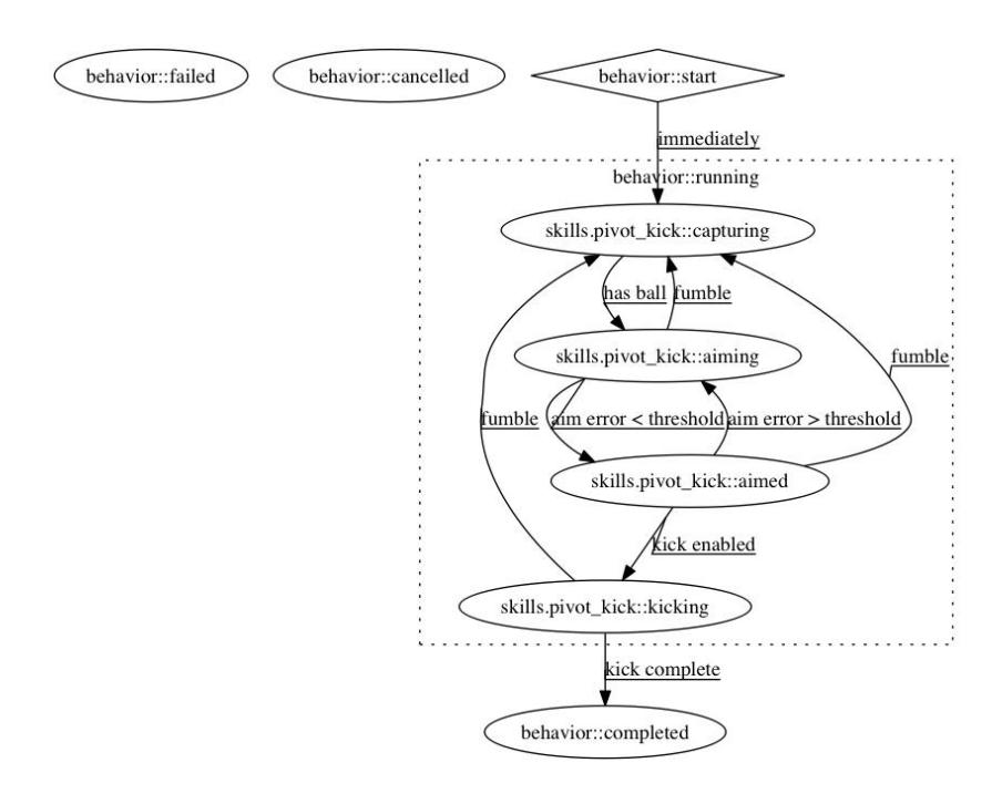
Hierarchical State Machines One design idea that is found throughout the new Python-based gameplay system is that every behavior class is a Hierarchical State Machine (HSM). The previous gameplay implementation had state machines in several places, but they did not share a common interface. This meant that sharing state information between behaviors was difficult. In the new implementation, every behavior has a few states that they inherit from the root superclass: start, running, completed, failed, and canceled. Subclasses can freely create their own states, but they are required to be substates of these. This creates a form of polymorphism that provides a common interface to every behavior throughout the system. One way that we have made use of this common interface is to create several generic "container" behaviors such as: TimedBehavior, and SequenceBehavior. TimedBehavior accepts a behavior as a parameter and allows it to run for a specified time limit. If it exceeds this limit, TimedBehavior cancels its subbehavior and enters the failed state. SequenceBehavior accepts a list of subbehaviors and runs them one after another, entering the completed state if successful. It is due to the rigid state-machine structure of the system, that generic behaviors like these are able to be implemented to encapsulate common patterns.
Another benefit of state machine-based design is that it is much simpler and clearer to analyze the logic of each behavior. A new textual output has been added to the soccer GUI showing the hierarchy of behaviors, including current role assignments and behavior states. In addition, we have written a script that is able to load every behavior and, using graphviz, export a state machine diagram of each one. Figure 8 shows an example of the diagrams this script produces.
3.3 Robot Firmware
Changing to the new mbed control platform required significant changes to the robot firmware. The primary advancement over the previous iteration is the inclusion of the Cortex Microcontroller Software Interface Standard (CMSIS). More specifically, the CMSIS-RTOS component of the standard was used to provide multitask operations between the robot's control loop and radio communications. Radio receptions are implemented using an interrupt service routine that is built upon a generic Communication Module firmware component. This component provides an abstraction layer between the low-level radio driver code and the higher-level packet handling logic. In other words, it enables the controls subsystem of the robot to view a packet and the packet's physical communication link as independent entities. Additionally, the Communications Module is able to handle multiple radios on a single robot, should the extra throughput be necessary in the future.
With the addition of an Atmel 8-bit AVR microcontroller (ATtiny441) to the kicker board, there are now three different programs that must be configured to the robot: mbed, ATtiny, and FPGA. The mbed and ATtiny components must have a binary file written to their internal flash memory while the FPGA must be configured at every startup from the mbed's on-board flash storage. In order to expedite this process, the mbed's firmware checks the ATtiny's firmware version against up-to-date files stored on the mbed's flash storage. If necessary, the mbed will re-flash the ATtiny at startup.
References
- RoboJackets Wiki. http://wiki.robojackets.org/. Accessed: 2015-02-23.
- Brett Browning, James Bruce, Michael Bowling, and Manuela Veloso. Stp: Skills, tactics, and plays for multi-robot control in adversarial environments. Proceedings of the Institution of Mechanical Engineers, Part I: Journal of Systems and Control Engineering, 219(1):33–52, 2005.
- Harold W Kuhn. The hungarian method for the assignment problem. Naval research logistics quarterly, 2(1-2):83–97, 1955.
- Qiang Liu, Changying Wu, Wenjing Zhu, and Jian Du. An ltcc bluetooth antenna with symmetric structure. In Signal Processing, Communications and Computing (ICSPCC), 2011 IEEE International Conference on, pages 1–4, Sept 2011.
- Robojackets RoboCup SSL Team. Robojackets robocup 2014 team description paper. Technical report, Georgia Institute of Technology, 2014.
- ZJUNlict RoboCup SSL Team. Extended tdp for robocup 2014. Technical report, Zhejiang University, 2014.