SSH Team Description Paper for RoboCup 2015
Thijs Emmerink, Rob van den Berg, Joost Overeem, Thomas Hakkers, Jeroen de Jong, Jasper van Ommeren, Ryan Meulenkamp
Saxion University of Applied Sciences
http://www.SmallSizeHolland.com/
Abstract This paper describes the RoboCup Small Size League team SSH from Saxion University of Applied Sciences. The hard- and software design of the robots, the software architecture and strategy are described. Furthermore, upcoming changes and improvements will be described.
1 Introduction
This paper describes the RoboCup Small Size team SSH from Saxion University of Applied Sciences. The team was founded in 2013 as a research project by five Applied Computer Science students. A new team has been working on the project each semester ever since the first team started, with varying results. In the second semester of 2014 a multidisciplinary team was created consisting of Electrical Engineering, Mechatronics and Applied Computer Science students. During this period our robots received a complete redesign in both hardware and software. Since this redesign, the robots have everything needed to compete in the RoboCup competition. In the upcoming semester a team of seven Applied Computer Science students will be working on improvement of the strategy and gameplay.
The following sections provide a description of the redesigned robots, the software architecture and strategy. The mechanical design will be described in section 2, the electrical design in section 3, the software architecture in section 4 and a conclusion in section 5.
2 Mechanical
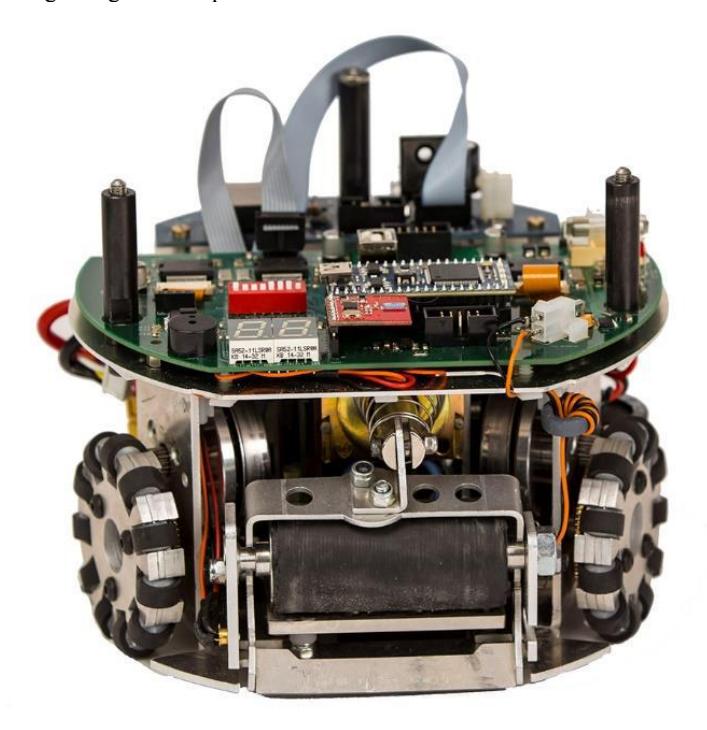
This year we started with a complete redesign of the robot, because the previous robot could be improved on: the kicker, the chipper, the dribbler and the drive module. These functions could not be implemented within the previous robot due to poor and impractical design. Also, the accessibility and maintainability of the previous robot could be improved significantly.
This new version of the robot has a lot of improvements regarding the problems stated above. Also, the robot is built from aluminium sheet metal instead of ABS.
2.1 Kicker
Within the testing phase of the previous robot we identified the following problems:
- The bottom section of the robot was too small to add a chipper mechanism.
- The previous robot was incapable of shooting the ball with a speed of 5 m/s.
- The mechanism was not stable enough and needed a lot of maintenance.
We created two new concepts. After testing both concepts we discovered that the concept 'impulse energy' shoots faster with the same solenoid and energy input.
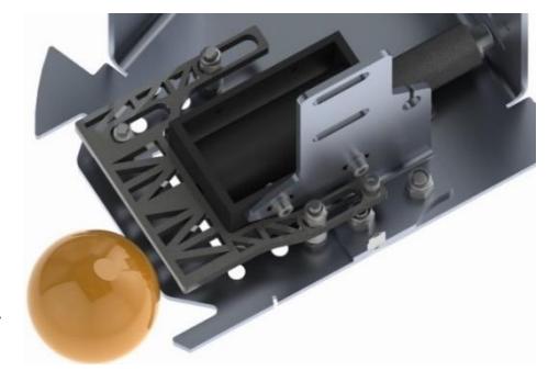
Concept impulse energy
The mechanism is based on the idea of a Newton cradle. In order to fire the ball, the plunger of the solenoid is fired first. It is important that the mass of the plunger is exactly the same as the mass of the ball. With the use of impulse physics we pass on the energy from the plunger (shown in Figure 1) to an intermediate mass (which has also the same mass as the ball) on to the ball. Theoretically, after one shot all the energy is stored within the ball. This makes the system very efficient. The intermediate mass and the plunger are then pulled back in start position with the use of springs.
To make sure the initial energy is enough to accelerate the ball to a speed of 8 m/s we have done some research on solenoids. We have tried to develop our own solenoids and have compared them to store-bought solenoids. After some experiments it turned out that store-bought solenoids perform better.
We apply a voltage of 360 V on these store-bought solenoids. With this high voltage we are capable of kicking the ball in excess of 8 m/s. With the use of PWM it is possible to control the shooting force and thus the ball speed, like described by G. Tao et al (2011). In order to ensure that the ball is in front of the kicker we use a photodiode in combination with an IR light source.
2.2 Chipper
The previous robot did not have a chipping mechanism. For the new robot, we have developed a completely new mechanism. The principle is based on a lever: on one side the solenoid pulls on the lever and on the other side the lever presses against the ball. The dimensions of the lever were calculated and tested afterwards with a test setup. By doing this we know the required dimensions for ideal shooting. This includes:
- Contact time with the ball
- Shooting angle
- Start and final angle of the lever
- Dimensions of the lever
- Solenoid specifications
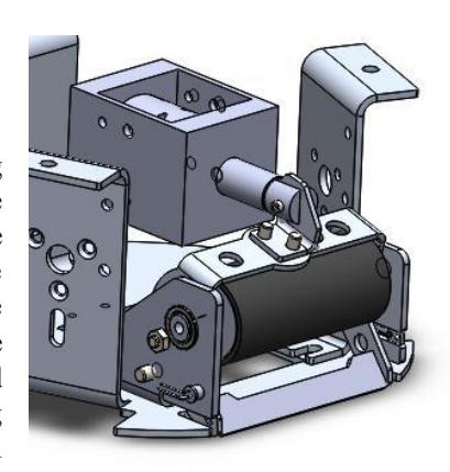
In the current chipper (shown in Figure 2), the mass and the shape of the lever is very important, because the moment of inertia has a big impact on the shooting distance. Just like the kicker we used a stock solenoid, which we will use with 360 volts. With the use of PWM it is possible to control the shooting distance. The chipper is capable of shooting over a distance of four meters.
2.3 Dribbler
During the testing phase of the previous robot we identified the following problems:
- The rubber surface of the old dribbler did not have enough grip
- The construction used a lot of space
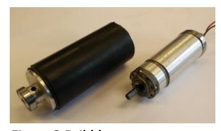
We have chosen to integrate the motor into the dribbler roller, so we could save space for the other ball control systems. These two components are shown in Figure 3. We tried to keep the dribbler simple: a drum is placed over the motor, this drum has a bearing on one end and the motor sticks out of the other. The 'motor side' fits into the roller. The position of the drum is fixed with a socket set screw. At the other side the roller has a bearing. The assembly can be mounted in the side frame of the chipper. The roller is covered in two soft rubber tubes, which are glued to the roller. Without the ball touching the dribbler rotates with approximately 1500 rpm. The rotations per minute will drop to a third of its original speed when it is in contact with the ball.
The dribbler performs really well when the robot drives back and forward, also it is possible to make a slow turn while dribbling.
2.4 Drive module
The previous robot had a 3D printed gearbox and store-bought Vex Omni wheel. Both gearbox and Omni wheels did not perform well and were too bulky.
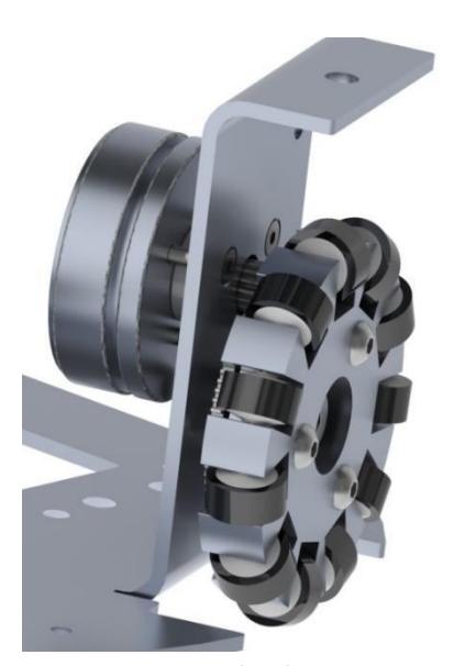
We have designed new Omni wheels made from layers of aluminum sheet metal, like shown in Figure 4. The wheels have a diameter of 60 mm and there are pinch rollers with 13 mm diameter. A lot of time was spent to find the best rollers for the Omni wheels. Pinch rollers from a tape recorder proved to have more than twice the grip of the Vex rollers, due to the rubber quality and the shape of the rollers (sharp corners).
A 15:80 ratio gearbox was implemented in the form of a direct drive on the wheel. Three Maxon EC45 Flat brushless DC motors are used to drive the three Omni wheels. We are planning to investigate a four wheel design in the future.
2.5 Frame
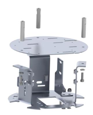
The frame is made of aluminum sheet metal. In order to save both weight and space, and keep enough strength, an optimized design is used. As seen in Figure 5, the frame consists of three flaps pointing upwards. The middle plate (where the motherboard is mounted) is bolted onto these flaps. This way the frame is strengthened in all DoF's, making the frame very sturdy. The flaps also have a second function, namely to support the driving motors and the Omni wheel axes.
2.6 Mechanical specs
Mechanical specifications of the SSH robot.
Mechanical specifications
| Property | Value |
|---|---|
| Mass | 2907.5 gram |
| Dimensions | 180x147 mm |
| Max. Ball coverage | 14.00% |
| Driving motors | Maxon EC-45 Flat 30 W |
| Gear type | External Spur |
| Gear | 15:80 |
| Wheel diameter | 67 mm |
| Dribbling motor | Como drills 6-12 V DC motor |
| Dribbling gear ratio | 4:1 |
| Dribbling construction type | Compact (internal motor) |
| Kicker principle | Impulse physics |
| Kicker speed | Max. 8 m/s |
| Chip distance | Approx. 4 m |
3 Electrical
The electrical systems of the SSH robot are designed to support all mechanical functions and provide control capabilities.
3.1 Motherboard
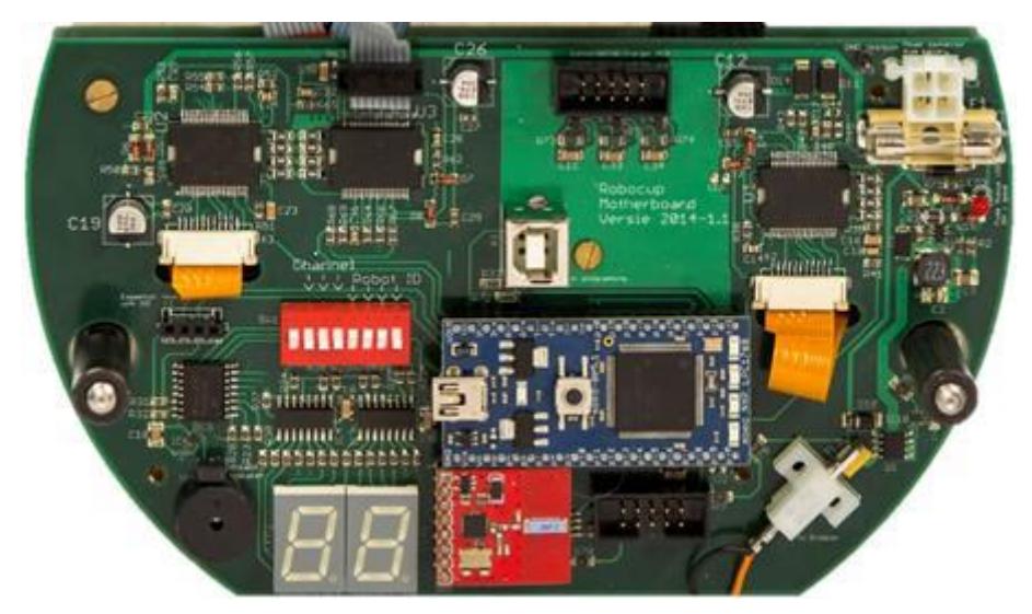
The motherboard, shown in Figure 6, is the main control unit of the robot. It controls everything and receives the information from the server via a 2.4 GHz transceiver. The controller of the motherboard is a NXP mbed LPC1768 module. This Dip-40 module is programmable via USB and has a lot of dedicated functions, such as PWM, TWI, analog inputs and an Ethernet port. Communication with the server is done with a nrf24l01 transceiver. This small module interfaces with the mbed via an ASPI bus. The received data is processed and used to calculate the actions that need to be done.
Each of the wheels is driven by an EC45 motor from Maxon. The motor itself is controlled by a P6235PD motor controller. Apart from some bias resistors and small RC-Filters not much is needed to use the P6235. The controller gets control signals from the GPIO pins on the mbed. Some signals are also fed back to the mbed. Those feedback signals are produced by hall position sensors in the motor. With the information of those two hall sensors, the speed and direction can be determined and used in the calculations (PID for example).
To power all electronics a LiPo battery is used. Our battery contains four cells in series, which results in a voltage of 16.8 V. Because this voltage is too high for the digital electronics, it needs to be converted to a more suitable level of 5 V. This is done with a Buck-converter, based on the MCP16301 from Microchip. Although it is fairly small it can deliver a current of up to 600 mA. Its efficiency peaks at 92%.
To be able to dribble there is a break beam sensor that indicates the presence or absence of the ball. This principle was chosen because it is a simple and reliable solution. The break beam consists of a NE555 timer that generates a 4.5 kHz rectangle signal and drives the infrared led. On the other side an infrared receiver is used with a fixed threshold. The receiver has a digital output that indicates if the threshold is exceeded or not. The fixed and high frequency helps detecting if the ambient light is interfering with the sensor. If the sensor outputs a constant high signal the ambient light is too bright and the sensor output unreliable. Tests indicate that the ambient light must be incredibly bright or very close to the sensor to interfere.
3.2 Charge discharge
To be able to kick or chip, two solenoids are built into the robot. They are used with 360 V. To generate this voltage, a fly-back converter based on the LT3757 is used. The energy converted by the fly-back converter is stored in two big capacitors of 470 µF each. The charging process is entirely controlled by the LT3757. A feedback line measures the voltage on the capacitors and stops the charging if the desired voltage is reached. After using a solenoid, the charging continues automatically. Because 360 V is quite dangerous, the fly-back converter is capable of discharging the capacitors to a safe voltage of 4 V in around ten seconds. The automatic action ensures that it cannot be forgotten to discharge. To indicate a dangerous voltage level, a led is installed.
The stored energy in the capacitors is transferred to the solenoids by big MOSFETs. Those MOSFETs are driven by MOSFET drivers. This is to guarantee fast switching and to protect the outputs of the mbed on the motherboard. In order to keep the connection between the capacitors, the switching part and the solenoids short, the MOSFETs and their drivers are on a separate PCB, which is placed on the side of the solenoids.
4 Software Architecture
The main focus of the software team has been to get the software ready to qualify for the 2015 competitions.
4.1 High level behavior
When new data from SSL-Vision is received the AI decides whether attack or defense mode is chosen and the corresponding high level behavior is called. The high level behavior decides what task (low-level behavior) gets assigned to each robot and where the robot needs to go.
4.2 Low level behavior
For each of the roles on the field we have a different low level behavior. These robot types consist of a keeper, defenders and attackers. The selected low level behavior calculates all data and sends this to the robot.
4.3 Path planning
Most SSL RoboCup teams use an implementation of the RRT or RRT* path planning algorithms. These algorithms work on the principle of randomly picking points to calculate the shortest route. We want a direct path so we went for a different approach.
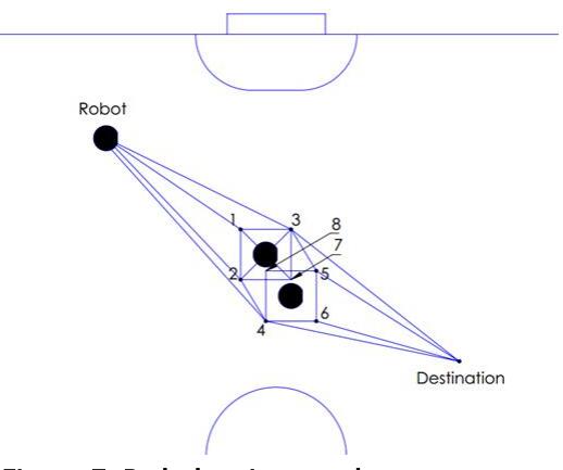
We construct a graph from the position data of the robots, where we draw four points around every robot. After these points are generated, we calculate the neighbors of each point and construct a route through this graph using Dijkstra's algorithm. This method ensures we find the shortest path in a graph, like described by Reddy (2013). In Figure 7 a situation is shown where two robots are blocking the way towards the destination.
4.4 Strategy
At the moment, we have eight different defense and attack tactics in the high-level AI. An algorithm decides which tactic is used based on various inputs. The inputs consist of information about the ball possession, the stand and the occupation of different zones on the field, by each of the teams. A part that is responsible for the self-learning in decisions is used as an input. The self-learning part keeps track of how successful previous decisions were.
Within each tactic, roles, such as keeper or blocker, are distributed to each robot. The tactic describes the distribution of roles. The roles describe the low-level behavior of the robots.
5 Conclusion
The current robot design described in this paper is a huge improvement over the previous design. All mechanical parts are functioning properly and are ready for a game. The motherboard is working completely, but we are not receiving the proper voltage from the charge circuit. We can still make a lot of improvements on the software. At this moment we have a working version which we can use for a game.
In the next few weeks we are introducing new students from Applied Computer Science to the project and will be working on improving our strategy and team play. We are looking forward to test our robots in matches at RoboCup 2015 in Hefei.
References
- H. Reddy (2013). PATH FINDING Dijkstra's and A* Algorithm's. [ONLINE] Available at: http://cs.indstate.edu/hgopireddy/algor.pdf. [Last Accessed 11-03-15].
- G. Tao, M. Chen, T. Zhang, (2011). Control characteristic of PWM solenoid valve in the electro-hydraulic shift system. Consumer Electronics, Communications and Networks (CECNet). (e.g. 2), pp.158-161