STOx's 2015 Extended Team Description Paper
Saith Rodr´ıguez, Eyberth Rojas, Kather´ın P´erez, Jorge L´opez, Carlos Quintero, Juan Manuel Calder´on, Oswaldo Pe˜na
Faculty of Electronics Engineering Universidad Santo Tom´as Bogot´a, Colombia
Abstract The 3rd generation of the STOx's team was designed and built in 2014 and tested in competition in the RoboCup world championship in Joao Pessoa, Brasil. After a thorough evaluation, we have performed important changes in its initial design in order to improve the team's general behavior. In this paper we describe the most significant changes made to the platforms as result of the experience in RoboCup. Also, we have created a framework that increases the robustness of the system's perception to the vanishing of the objects within the field. We present experiments where we vary the level of vanishing and evaluate the average system's performance. These tests show improved performance of the framework, even in presence of high levels of noise and vanishing.
1 Introduction
The STOx's team has been participating in the RoboCup world initiative since 2011 (Istambul, Turkey), for 4 years in a row achieving the world's top 8 teams for the last two years (2013, 2014) for our participation in Eindhoven and Joao Pessoa respectively. The experiences gained during those years in the competitions, the interaction with other team members, the competitive environment in the games and the information found in the team description papers have produced a variety of changes and improvements in the robots and the team.
In 2014, a new set of robots, the 3rd generation of the STOx's team was assembled from scratch by taking all the gained experiences during the last four years and changing certain design parameters that aimed at improving the accuracy, reliability and robustness of each robot and that of the whole team. The most significant changes included in the 3rd generation of the STOx's team were related to the robot mechanics and electronic design parameters and strive to obtain robots that behave as close to the simulation performance as possible.
In the following section we briefly mention some of the most basic features of the new STOx's 3rd generation of robots, next we describe minor changes performed on the 3rd generation design after the 2014 RoboCup competition in Joao Pessoa. Then, we show the process chain followed by the data after it is acquired by the vision system. Finally, we show a framework developed by us that dramatically reduces the problems caused by noise in the vision system and show its performance in the ball tracking procedure when exposed to different values of noise.
2 STOx's 3rd Generation
The 3rd generation of the STOx's team was designed, assembled and tested in competition in 2014 for the RoboCup world championship in Joao Pessoa, Brasil. Its main features included updates in the design of wheels, dribbler system, kickers, motors and main board, among others. The target in mind when designing and building the 3rd generation was to ended up with robots that behave as close as possible to those in simulation, specifically, in terms of accuracy, reliability and robustness. For this reason, the most significant changes were focused on mechanics and electronics and few changes in the Artificial Vision system and the software controller.
A thorough evaluation of the platform's performance after the competition in 2014 was performed in order to tune certain design parameters and also for improving the robot's kinematics, aiming for smoother movements and more accurate control. These changes are shown in detail in Section 3 and strive for improve the general robot's behavior for the RoboCup in 2015. Detailed description of the STOx's 3rd generation design can be found in the STOx's TDP [9] and ETDP [10] of 2014.
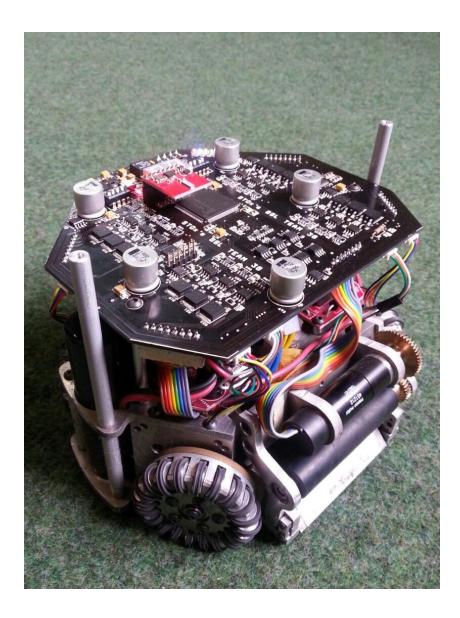
Fig. 1 shows a picture of one robot of the 3rd generation of the STOx's team with the new modifications made after the RoboCup competition in 2014. In Table 1 we show the main characteristics of the STOx's 3rd generation team.
Table 1. Main features of the 3rd generation of the STOx's team
| Diameter | 178mm |
|---|---|
| Height | 125mm |
| Weight (Approx) | 1.5Kg |
| Nrollers | 20 |
| Wheel diameter | 55mm |
| Calculated Max Speed 4m/s | |
| Calculated Kick Speed 10m/s | |
| Max chip distance | 5m |
| Chassis | Aluminium 7075 |
| Wheel Motors | EC45 Flat 50W |
| Dribbler Motor | EC16 Maxon |
The following section illustrates the upgrade made to this new generation after the RoboCup world competition, specifically in the electronic design.
3 Electronics upgrade
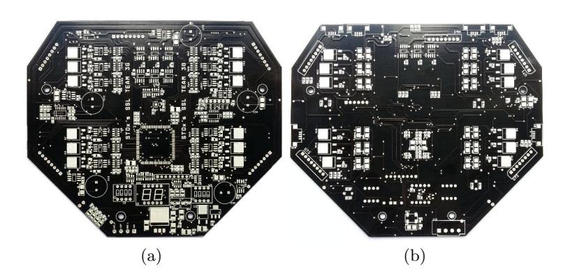
The main changes in the robot's electronics are related to the control of the 50W motors. In order to improve the commutation we decided to change the channel P MOSFETs for channel N MOSFETs, to guarantee near identical switching time (time between ON OFF and vice versa almost equal to 60ns). Also we have changed the drivers by ones with floating channel design for bootstrap operation (IRS2011). These new considerations implied significant changes in the mainboard that required the design and construction of a new mainboard, as shown in Fig. 2.
The major benefit of the new electronics is that it allows an increase in the motors speed, that is reflected in an increase in the robot speed. However, the price includes a decrease of the robots autonomy due to the increase of consumed energy (about 10%).
4 Preprocessing
In this section we present a framework developed by us and used in the SSL STOx's team in order to acquire the information captured by the vision system, pre-process such data, perform especial tracking algorithms and finally create one unique virtual representation of the physic world. This virtual world shall then feed the artificial intelligence module that is finally the responsible for making all the decisions in the game.
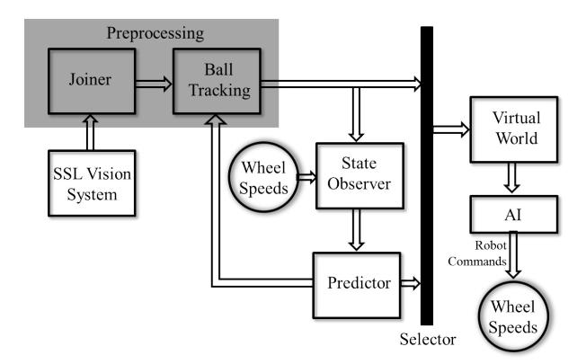
Fig. 3 shows a block diagram of the processing chain followed by the data acquired through the cameras and delivered by the SSL vision system. It describes the processes implemented in the STOx's software in order to create one coherent virtual world as a faithful representation of what is happening in the game field. Specifically, such virtual world is composed of a set of features that contain certain physical values and measurements of the elements and actions within the field, i.e., the robots and the ball.
4.1 Joiner
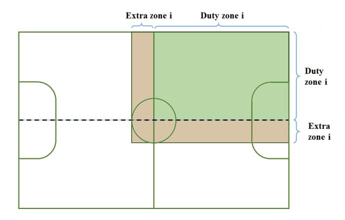
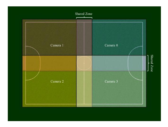
The first step within the processing chain consists of receiving the data that come from the SSL vision system and transform them accordingly. These data consist of a set of recognized items within the field with its corresponding position at a rate of 60 fps (i.e., approx each 16ms) for each one of the 4 cameras. The first module named Joiner is the one in charge of transforming the data coming from the set of cameras that provide global vision into one single set of observations within the field. In our framework, any object in quadrant i of the field should be detected by camera i (for i = 1, 2, 3, 4). However, in practice, each camera covers a wider area within the field than just the one corresponding to quadrant i. In our algorithm we define two vision zones for each camera as shown in Fig. 4.
4.2 Ball Tracking
The Ball Tracking module shown in Fig. 3 takes as input the data output by the Joiner module which consists on one single representation of each object detected by the SSL vision system, instead of one representation per camera. Under this scenario, it is common to find that the vision system detects several false balls inside the field during short sets of frames in a random fashion. The objective of this module is to keep a close tracking of the real ball to ensure that the artificial balls created by noise in the vision system do not jeopardize the team's behavior by assigning the location of the ball in any of these false ball locations.
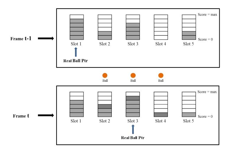
Our algorithm maintains a finite set of slots used to store the information of each detected ball inside the field. Each ball slot contains at least the coordinates inside the field that correspond to the detected ball as well as a score. The score of a ball slot is a normalized measure of the number of frames that the vision system has detected such ball: the greater the score of a ball slot, the larger the chance that such ball corresponds to a real ball.
In steady state, the algorithm maintains a pointer to the slot that corresponds to the real ball inside the field, with its respective coordinates and score. All other slots are assumed to be false balls in the field. From time frame t − 1 to time frame t, several situations may occur as follows:
- One or more new balls are detected in frame t: In this case, if there are empty slots, new slots should be occupied by the new balls.
- One or more of the balls detected correspond to an existing slot: In this case, the score of those slots shall be incremented.
- One or more of the ball slots are not detected in time frame t: In this scenario, the score of a ball that has been detected before but not in the current frame is reduced. If the score of a ball reaches zero, such ball slot is eliminated from the set.
The last situation contains a special consideration: if the ball that is currently considered to be the real ball is not detected in the current frame, then, its score is reduced and its coordinates features are predicted using the information of previous frames through the Predictor module (described later in Section 5). This means that if the ball that is considered to be real is not seen in the current frame, we use as coordinates the values provided by the predictor only if the real ball pointer still pointing at such ball slot (i.e., if after the reduction in score, such ball remains the real ball). Under this scenario, the system is resilient against possible noise in the data acquire through the SSL vision for the detection of the real ball. If the real ball is missing during a short set of time frames, the system will decrease its score and predict its coordinates based on the information available in previous frames until other ball slot obtains higher score. In the latter situation, the real ball pointer will point to the new slot, and hence the real ball will be considered to be that.
Fig. 6 shows the situation of 5 ball slots in time frame t − 1 and time frame t.
5 Virtual World reconstruction
The output of the preprocessing module is a list of objects inside the game field detected by the vision system, each with a unique joined representation (i.e., a single ball and one representation for each robot) expressed as a set of features composed mainly by spatial coordinates. At this point, the entire processing chain becomes highly dependent of the quality in the vision system. The preprocessing modules can not do better than what is provided by the SSL vision module. For this reason, the final step of our framework strives for reducing this dependency in such a way that the representation of the virtual world is not jeopardized when certain levels of noise appear in the vision system.
In order to achieve such target, we have included three additional modules in the processing chain, namely the State Observer, the Predictor and the Selector as shown in Fig. 3. The functionality of such modules is described next:
- State Observer: The State Observer is a module that is in charge of monitoring the data coming from the vision system after it has been preprocessed by the Joiner and the Ball Tracking module. Also, this module computes additional features based on the vision's system observations. Specifically, this module computes the velocities of the objects within the field based on each object's position among the time frames.
- Predictor: This module receives the values observed by the State Observer in each frame and use it to feed a computational model of the physical world. The model consists of a mathematical library capable of simulating the system's next state by using the information from previous time frames (past and current states). We have used the Open Dynamics Engine (ODE) library through its C/C++ API [11] in order to simulate the movement of the robots and that of the ball in the field. This simulation is based on a computational model of the robots, the ball and their interaction with the carpet, requiring the tuning and assignment of certain parameters that define these objects. A special consideration is posed in the parameter that models the friction between the robot wheels and the carpet, since it may significantly vary for different fields. We have performed an experiment that allows us to estimate the friction coefficient between the robot wheels and our lab's carpet, as follows:
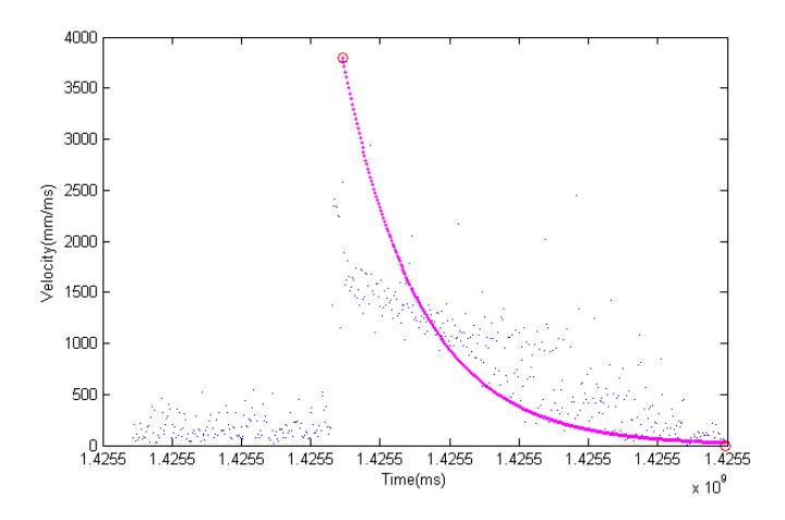
We recorded the trajectory of one ball that started with maximum speed and measure the speed at each frame and the time until the ball finally comes to a stop. The Eq. 2 relates the Friction with the velocity of the ball during its trajectory:
$$Friction = \beta V_{in} \exp\left(-\frac{5}{\tau}t\right)$$
where β is the coefficient friction and Vi is the initial velocity of the ball. Fig. 2 shows the experimental values of the trajectory.
We have linearized the observations around an operation point using a first-order Taylor series. This approximation provided us with an approximated value of the friction coefficient.
– Selector: The Selector is managed by the State Observer and is the one in charge of deciding which information will be used to ultimately create the Virtual World: the data coming from the Vision System or the data output by the Predictor. The thumb rule is that the data coming from the Vision System will always have higher priority and will be the one that should be used to create the Virtual World. However, when the State Observer identifies an object (ball or robot) in the field that the vision system is not detecting in the current frame, but that it was correctly detected in previous frames, then, the position, velocities and other physical attributes related to such object will be taken from the Predictor and will be used to create the Virtual World.
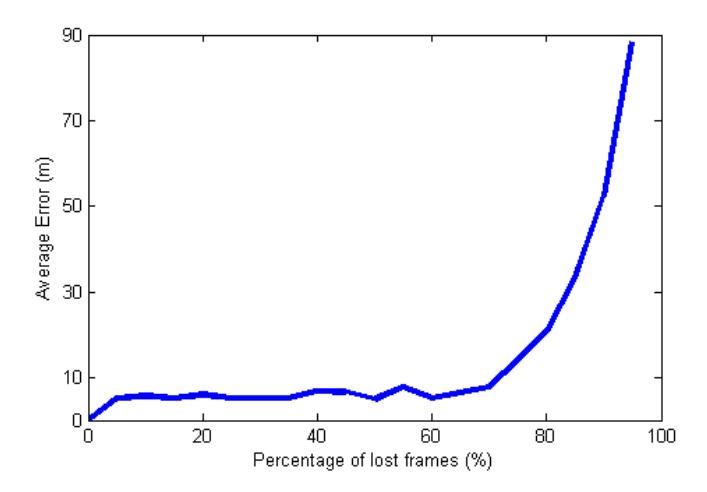
We have created a set of experiments to characterize the performance of our framework in presence of different percentage of lost frames. For this, we have recorded a trajectory of the ball inside the game field, making sure that no frames are lost during the process. Then, we have randomly chosen a percentage of the total recorded frames and deleted such data to simulate frame lost. We have used these new masked data with our framework and evaluated the error produced when one frame is missing and our framework predicts the position and velocity of the ball in such frame. The error of the total trajectory is the sum of the Euclidean distance between the predicted position and the real position. We have ran this experiment 100 times for each percentage of lost frames and calculated the average error for values of percentage between 0% and 95%. These results are shown in Fig. 8.
It is noteworthy that the average error increases as the percentage of lost frames also increase. This is a expected result since the more lost frames, the less accuracy should be expected from the Predictor Module. Notice, however, that using our framework, it seems feasible to obtain a fair virtual world representation even in the presence of roughly 70% of lost frames.
6 Conclusions and results
Our 3rd generation of robots has gone through a variety of changes after our participation in RoboCup 2014, especially in the electronic design. We have also proposed the implementation of a new framework that strives to reduce the risk of jeopardizing the virtual world representation acquired by the SSL vision system that is based on a mathematical model of the field and the robots. Experiments on real recorded data has shown that such framework makes the system behavior more robust to noise in the vision system.
References
- Skuba 2012 Extended Team Description. http://robocupssl.cpe.ku.ac.th/tdp/etdp2011/SKUBA ETDP 2011.pdf
- Skuba 2011Extended Team Description. http://robocupssl.cpe.ku.ac.th/tdp/etdp2011/SKUBA ETDP 2011.pdf
- ZJUNlict Extended Team Description 2012. http://robocupssl.cpe.ku.ac.th/ media/robocup2012:2012 zjunlict etdp.pdf
- FOSLER, R.: Generating High Voltage Using the PIC16C781/782. Application note, Microchip Technology Inc. (2005)
- BRUCE, J., VELOSO, M.: Real-time randomized path planning for robot navigation. In: Proceedings of the IEEE Conference on Intelligent Robots and Systems. (2002)
- RODR´IGUEZ, Saith and ROJAS, Eyberth.Diseo e implementacin de un equipo Small Size robot League para la RoboCup, Universidad Santo Tomas, 2010
- PAVON, Juan. PÉREZ, Jos. Agentes software y sistemas multi-agente. Prentice Hall. 2004.
- RUSSELL, N. Inteligencia Artificial: Un Enfoque Moderno. Prentice Hall, 2004.
- Rodr´ıguez, Saith, et.al. STOx's 2014 Extended Team Description Paper. http://robocupssl.cpe.ku.ac.th/ media/robocup2014:etdp:stoxs 2014 etdp.pdf
- Rodr´ıguez, Saith, et.al. STOx's 2014 Team Description Paper. http://robocupssl.cpe.ku.ac.th/ media/robocup2014:tdp:stoxs-2014.pdf
- Smith, Rusell. Open Dynamics Engine. Available at http://www.ode.org/ode.html