2015 Team Description Paper: UBC Thunderbots
Scott Churchley, Ryan De Iaco, Jonathan Fraser, Somik Ghosh, Christopher Head, Sarah Holdjik, Nicolas Ivanov, Stephen Johnson, Fakherdin Kalla, Alice Lam, Bruce Long, Kevin Lu, Sarah Ng, Koushik Peri, James Petrie, Emmalee Roach, Wei Yi Su, Brian Wang, Cheng Xi, Komancy Yu, Kevin Zhang
Mechanical Engineering, The University of British Columbia; Computer Science, The University of British Columbia; Electrical and Computer Engineering, The University of British Columbia; Engineering Physics, The University of British Columbia; Applied Science, The University of British Columbia
Abstract This paper details the design changes UBC Thunderbots have made over the past year in order to improve our robots for RoboCup 2015. The most significant changes include improvements to the control systems, navigational and ball filtering algorithms, and the dribbler.
1 Introduction
UBC Thunderbots is an undergraduate SSL team at the University of British Columbia that has been competing at RoboCup since 2009. After analysis of our robots' performance at RoboCup 2014, we have planned and begun to implement several design changes that we believe will provide significant advances to our robots. Many of the proposed changes are still under development, so final implementation details and testing results will be included in future TDPs. The proposed changes, which include improvements to our control systems, navigational and ball filtering algorithms, and dribbling mechanism, are outlined in the following pages.
2 Mechanical Design
2.1 Dribber
A continuing concern with the current robot dribbler design is that the dribbler does not trap a moving ball on first touch. Slow motion video shows that when the ball contacts the dribbler apparatus at speed, the roller — which is always running — imparts a downward spin to the ball, and in reaction, pushes the dribbler apparatus upward. The ball bounces off, though its top spin brings it back to the dribbler. The double-touching penalty renders this occurrence undesirable. The Dribbler Re-design team sought to create a damping mechanism that would allow a greater chance of initial entrapment of a fast moving ball.
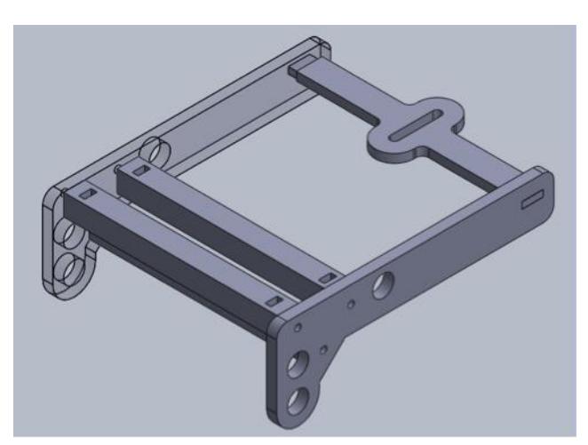
After examining several options, the team has opted for designing a jawbone dribbler apparatus levered with an internal magnetic damper. The advantages of such a design include fewer moving parts and fasteners, easier manufacture and assembly, and more balanced mass distribution. There are several challenges in implementing such a design, however, including difficulties in designing the dampers, integrating the breakbeam into the new dribbler apparatus, and constraining the necessary components of the dribbler assembly. The team has designed a prototype for the jawbone apparatus, shown in Figure 1, for sizing and simple testing. The team has also designed and fabricated a damper mount device, with which damper optimization tests can be performed.
The next steps for the team will be to iterate the jawbone apparatus, to optimize sizing and fastening. Once data from the damper mount tests are available, the team can proceed with integrating the damper components to the jawbone and to the robot itself.
2.2 Shell
We are currently designing new shells for our robots that will facilitate easier switching of identification dots and improve durability. The outer casing of the robots will be made of polycarbonate to reduce weight while providing protection of mechanical and electrical components during impact. The top part of the case will contain cutouts of the standard dot pattern, so that team members can quickly mount the colored paper given at the competition without having to cut precise circles.
2.3 Drivetrain
The goal of the drivetrain design this year is to solve two problems: the wearing that occurs on the motor mount screw hole and the potential of carpet fuzz getting stuck in the gears.
The main source of the wearing on the motor mount screw holes is the vibration produced by the running motor and axial force on the screw when the bot is changing direction. In order to fix this problem, we will be changing the motor mounts material to a stronger and harder one (steel). This change will not only increase the life span of the drivetrain mount, but also bring down the centre of gravity of the entire bot.
The carpet fuzz issue is primarily caused by the mechanical structure of the omniwheel used in current bot, which pulls up the carpet fuzz. A simple solution will be to add a layer of isolation between omniwheel gears; in this way, we will stop the fuzz to some degree while maintaining the current design.
2.4 Chipper
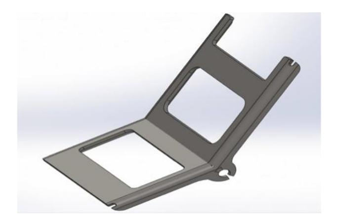
A concern with the current chipper design is the amount of vertical structural space consumed. By allowing for a bent/angled chipper plate, shown in Figure 2, the solenoid would be able to act horizontally. We originally thought of a single piece chipper plate with a bent angle; however, manufacturing would be highly difficult and mechanical durability would be an issue. By allowing for a two piece plate fixed by a conjoining slot piece for fixed angle, the chipper allows a solenoid to be act horizontally, thus saving occupied space for the component.
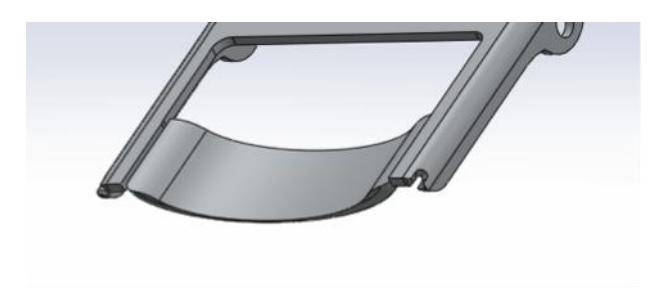
Another issue lies in the lateral movement of the ball while dribbling. In order to counteract this problem, a curve or groove, shown in Figure 3, may be placed in the front of the chipper where the ball is held to allow for more accurate chipping/kicking action.
3 Electrical Design
3.1 Electronics
The electronics have mostly remained unchanged this year. The electronics components, as of last year, consist of the main board, chicker board and the breakout board. The main board hosts the computation elements, communication links and motor driver. It went through a major revision last year, in which we added a 32-bit ARM controller alongside the FPGA. The motor drivers were also upgraded to discrete-MOSFET drive configuration to improve driving efficiency and PWM resolution. Details of the redesign are noted in our 2014 TDP [1]. The chicker board hosts the boost converter and high voltage circuitry for kicking and chipping. The core of the design, i.e. the charging and switching circuit, hasn't changed since 2010, though we have been making an effort to make the high-voltage elements safer. The breakout board is designed to bridge the main board with the fragile motor connector, encoder connector and other components through a high density, high durability connector. The detail of the breakboard is not elaborated here due to its simplicity, but the design of main board and chicker board is outlined below.
Main Board Architecture
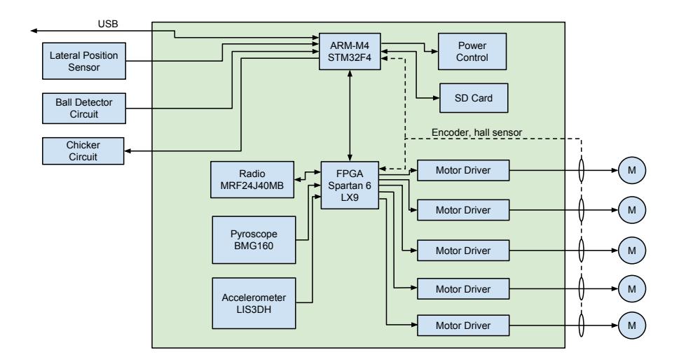
The main challenge the electrical team faced before the 2014 redesign was the limited processing power that can be fitted onto a Spartan 6 FPGA with 9,152 logic elements. Constraints in our manufacturing ability limit the FPGA package to TQFP. The problem is compounded by the lack of open-source microcontroller softcores that are both small in footprint and error-free. In 2014, we chose to increase processing power at the expense of some loss in programming flexibility and introduced a STM32F405 along side of the existing FPGA.
STM32F4 introduces a number of peripherals so we were able to move most electrical interfaces from the FPGA to the microcontroller. The addition of the microcontroller allowed us to have access to high speed SD card storage, powerful floating point unit, breakpoints for debugging, etc. As a companion to the microcontroller, the FPGA takes on the role as an offload engine for tasks that require too much CPU attention, e.g. radio communication. Communication between the microcontroller and the FPGA is established through an SPI bus and is thoroughly described in our 2014 TDP [1]. Figure 4 shows the main board architecture.
Chicker Board and Recent Improvement
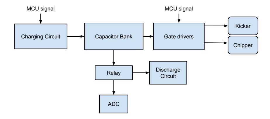
The Kicking and Chipping actions are operated through discharging a 4mF Capacitor Bank operating at 240V DC, as shown in Figure 5. Safety is a very important concern at such high voltages, and so care must be taken to avoid a risk of shock to team members or confusion about the charge state of the capacitors after an unexpected robot shutdown. In normal operation, the capacitors are discharged through the kicker and chipper solenoids in a few seconds. However, in the case that the robot is shut down unexpectedly with the capacitors charged, an on board relay switches the capacitors to series resistors to dissipate the energy stored.
In the previous year, two small series resistors were used to discharge the capacitors. Unfortunately, the power dissipated was too large and these resistors were failing. We have replaced the small resistors with a single high power resistor resistor, which discharges the capacitors to a safe voltage in a few seconds without overheating. In addition, there are plans to add a series indicator circuit with an LED to express the capacitor voltage level.
3.2 Controller Upgrade
This year, we shifted the focus of the electrical team to upgrade the control aspects of the robots. With an abundance of computation power and addition of motion sensors, our existing robot hardware has plenty of potential for better controllability. This section outlines a number of control project that are taking place this year.
Movement Primitives
The control system loop used by Thunderbots in previous years is fairly typical of SSL RoboCup. There are immediate feedback sources located on the robot, including accelerometers and gyros, with the most accurate feedback coming from the wheel encoders. The overall positional loop is regulated by the camera feedback. Like most systems, this positional feedback is located within the command and control computer with each robot only maintaining a local velocity control.
This design poses some significant challenges when trying to achieve maximal performance from the robots. Because the camera loop is delayed by approximately a quarter of a second, a significant amount of play can occur between the current time and when a camera frame was last valid. The solution to this is forward simulation, wherein the current gamestate is deduced by simulating the game forward in time from the previous camera frame. This method has serious problems when it occurs in the control computer, as it is not omniscient. First and foremost, if the one of the robots under its direction experiences a disturbance, such as a collision or wheel slippage, the disturbance will not be appropriately taken into account. There is a solution to this problem, however, as each robot via its sensors has access to a greater amount of information with little to no significant time lag. Other teams [2] have solved this problem by moving the entirety of their positional control onboard the robots, directly sending the camera frame out over the radio channel and performing the sensor fusion onboard.
This year, we have decided to solve this problem in a subtly different way. Thunderbots utilizes the STP methodology [3] within its higher level AI. Skills, the bottom layer of the AI, handle the simple movement capabilities of the robot: moving in a straight line, rotating in place, pivoting around a point, etc. Typically these are computed in the command and control computer, broken down into a series of trajectories and fed into the higher level positional control loop. However, due to the previously mentioned delay this can introduce oscillations and aberrant behaviour. Our solution is to merge this bottom level of our AI with the robots directly, transmitting these actions wholesale as a form of trajectory programming in the robot. This allows the robot to rely on internal dead reckoning for most of the action, only loosely relying on the vision frames for fine tuning the positioning near the end of the movement when the robots velocity has slowed and delay does not pose as significant a problem.
Dead Reckoning
This project aims to combine data given by all motion sensors on the robot and allow the redundancy of motion sensors to improve the accuracy of position or velocity estimated by the the robot. The position and velocity information should feedback on to the control algorithm on the robot and improve motion control. The sensors that we need to fuse together are the 1440 count/revolution wheel encoders, accelerometer and gyroscope. The camera data acts like a high latency feedback that adjust for any drift in position. This project is ongoing and we may report on its progress in our next technical design paper.
Improvement on Chipping and Kicking
One issue we had with our robots previously was the inability to precisely control the velocity of kicking or distance achieved through chipping. At first, we tried to mathematically model our chipper/kicker (chicker) discharge circuit as an RLC circuit, scaled by a constant to account for losses. Unfortunately, this was too simple of a model, and was not able to accurately fit our observed data. We attempted to test many variables such as coil temperature, peak voltage, and discharge voltage in order to isolate issues. This, however, did not lead us toward an improved model. Through this further testing, we discovered that part of the problem was inconsistency across our robot's chicker solenoids in terms of DC resistances; many coils had resistances that were twice as high as others. From here, we opted for a calibration approach to improve the precision of our chicker system. We found that kick velocity varied approximately linearly with capacitor discharge pulse width and that chip distance varied approximately parabolically. We logged data from many kicks and chips, and fitted first and second order polynomial functions to the data, respectively. In the future, we are looking to create a lookup table with specific formulae for each robot, as well as implement software that can allow users to quickly change the formulae based on new input data.
Once we had functions that worked well with the desired range of inputs, we began improving our user interface for testing the chicker system. Originally, we had to specify the capacitor chicker pulse width when testing with the robots. Our new formulae allowed us to easily alter the user interface to specify a velocity (in m/s) for kicking and a distance (in m) for chipping. These improvements allowed for all of our members to better understand and use our testing user interface.
Lateral Position Sensor
Motivated by the limitation of the SSL vision system in latency and resolution, we decided to experiment with the idea of adding ball detection mechanism to our robot. The intention is to close the control loop with faster feedback.
The lateral position sensor is an array of 4 infrared emitters and receivers mounted on top of the dribbler. The sensors are driven in multiplex fashion and then processed to produce a plot, with very low spatial resolution, of the amount of obstruction in front of the dribbler as a function of the distance from the centre of the dribbler. Since all of the signal processing is performed by a microcontroller, the computation is simplified as much as possible. The mean and variance are computed from the relationship between amount of obstruction versus position. In the algorithm implemented, the mean produces the position of the ball and the variance determines whether a ball is present at all. A number of mechanisms are included to bridge the model with reality, including accounting for constant reflection of the IR light caused by the robot itself.
3.3 Long Term Research
The team is currently researching the possibility of installing mini cameras on robots to perform ball detection. The camera setup is expected to replace the lateral position sensor and will allow robots to see the ball not only when it is in close vicinity but also when it is not within the robot's immediate reach. Currently, the camera setup is still in the development phase and will appear on our 2016 robots. The purpose for adding ball detection capabilities on individual robot is to reduce delay and noise from the SSL vision system and return more reliable coordinates of the ball relative to the front of the robot. The data will be used by the controller to help determine a course of action and fine-tune movements when approaching or kicking/chipping ball.
The new camera setup will include a CCTV camera with QCIF resolution and a microcontroller (STM32F4) dedicated to image processing. Due to limitations in processing power, the algorithm needs to be inexpensive. The algorithm will process the YCbCr data from the camera, ignore the illuminance component to reduce noise from shadows, and find all the orange pixels in the field of view. Using the locations of the orange pixels, the algorithm will compute the location of the ball.
Currently, the algorithm in development calculates the mean and variance of the location of orange pixels in the image data and can successfully find the centre of the ball with good accuracy given that there is no other orange items apart from the ball in the field of view. The algorithm can run at approximately 200 Hz, which greatly exceeds the refresh rate of the camera (15-30 Hz). The next development stage involves increasing the robustness of the algorithm to reduce noise when there are other orange elements within the field of view. A potential solution is to calculate the skewness to give a measure of confidence for the coordinates. Increasing the resolution will also be investigated, as it will decrease the margin of error.
4 Software
4.1 Kalman and Ball Filtering
One of the challenges faced by the AI is to take in the multiple possible ball locations provided by vision and determine where the real ball location is. As with any real world sensor data, there is noise in the readings. This noise needs to be accounted for and, ideally, isolated and removed from the input. One method used by many systems to smooth out noise in a system is a Kalman filter, which makes use of the sensor's measurements, previously estimated locations, and control inputs into the system to provide both an estimate of the value and standard deviation of the current state of the system. We have used a Kalman filter for many years with success but in the past few years work has been performed in attempt to improve the ball filtering within the AI.
Last year to filter the input into the Kalman filter the following algorithm, based off of a particle filter, was used to determine the approximate location of the ball from the given vision input:
- Divide up the field space into bin of a given size.
- For each ball found in vision add a certain number of particles randomly distributed in a gaussian distribution around the ball location with a standard deviation set by a parameter in the AI.
- Given all the particles find the most likely location of the ball.
Some improvements being considered this year are to improve the ball filtering implemented last year and described above to become a fully functional particle filter or to consider alternate methods for filtering inputs from vision into the Kalman filter. Improving the ball filtering to become a fully functional particle filter will involve making use of history in order to help better predict the location of the ball. With a fully implemented particle filter, the Kalman filter will be redundant and could be removed if it was shown to have poorer performance.
The essential goal of these changes is to improve the accuracy on the AI's perceived location and velocity of the ball. Having an accurate read on the position and velocity of the ball is crucial to overall success and to the ability of the robots to perform tasks such as interceptions and passing.
4.2 Navigation
Our currently implemented navigator is a rapidly-exploring random tree (RRT) that branches out in random directions at set interval. Due to the random nature of this algorithm, it is not guaranteed to find an optimal solution, and also produces a noisy path: one that generates tremulous segments instead of long lines. This causes the robots to quiver during all movement and greatly reduces the speed of travel.
This year's proposed solution is to rewrite this algorithm, taking into account that SSL fields are sparsely populated. The simplest navigation algorithm is to draw a straight line from the starting position to the destination, ignoring all obstacles — and indeed, this works well when there are no obstacles. This is often the optimal solution in SSL, and even more so after the recent shift towards double-sized fields. However, we must consider situations where a collision does occur. In these cases, we take the convex hull of all objects that intersect the line. Next, the convex hull is spliced into the existing line, producing two different possible paths: one following the hull counterclockwise, and the other following the hull clockwise. The previous procedure is recursed on these two output lines until no more collisions occur. Now, we have two paths to the destination which are equally valid.
To implement the convex hull algorithm, we approximate all field elements with a finite set of points. The robot and ball are circles, which we approximate with 16 points along the circumference. The defense areas are a combination of lines and arcs, which we also approximate with points. The algorithm used is Monotone Chain, which runs in $O(n \log n)$ [4].
There are a number of further cases that we need to consider. First, robots have a radius, which means that the paths need to leave a certain gap between the actual hull and the path. This can be easily solved by pushing out the points that are used to approximate the shape. Second, choosing the side of the hull to follow is important. If this is recalculated each tick, the algorithm may switch sides rapidly due to noise, causing no movement to occur. In order to stop this from happening, once the robot gets close to the branching point of the hull, the robot needs to choose one side and keep that state. Finally, the path may exceed the boundaries of the field. In this situation, the robot should follow the path until it would exceed the boundaries.
While the convex hull approach may not provide optimal paths, the requisite calculations can be carried out quickly and with a much lower overhead than our existing navigation algorithm due to the sparse nature of SSL fields. With this approach, we are explicitly trading off optimality for speed, which we believe will prove to be worthwhile.
4.3 Machine Learning
In order to make our AI more competitive, we decided to implement a Machine Learning component that would run parallel to our AI and gather information on the game to aid future decision related to executing different plays in our playbook. Our goal with the general design of the system is to develop a system that can contain different machine learning algorithms for the different plays that we have. Since we also want to provide an easy API for our high level plays to access this information, we wanted to come up with a design that separates the interface of this API from the actual implementation so that both could work independently and could progress through our software work pipeline at different stages. By separating the implementation from the interface, we could dynamically change which machine learning algorithm we want to use to predict a future event for one of our plays during game time if we notice that one algorithm doesn't work as expected. Another constraint for our new system is that we wanted to put our machine learning system on a separate thread as we didnt want the computations in our machine learning system to affect the timing of our AI thread.
One of the main machine learning features that we are trying to implement for this year is a way to predict opponent robot formations a couple software ticks in the future using the work on Markov models of one of our members [5]. The rest of this section describes the minor changes we had to make to the model.
In our system, the Markov model runs parallel to our main AI and receives vision packets which it uses to collect data on robot positions and velocities for our transition table. Furthermore, we wanted to increase the granularity associated with the number of possible grid values for our states as we wanted a finer level of precision in our predicted result than the six used originally in the paper
During testing, we checked the accuracy of this system by comparing predicted formations with actual formations. Preliminary results in testing this system show a low success rate, for which there are several reasons. One of the things we noticed was that our system does not filter the incoming vision packets to discard packets from when the gameplay is paused, which ends up clobbering our transition tables with inaccurate information. One way to fix this is to read and process referee packets as well so that we only use data from vision packets sent during certain aspects of the game only.
Another area that we need to improve is handing out penalties for inaccurate predictions. Whenever a prediction is incorrect, we continue without decreasing the probability so there is nothing stopping the system from returning that same formation again next time. The simplest way of penalizing the system is to multiply the probability by a random number below 1 but discovering the multiplier would require extensive testing.
Overall, there is still a lot of work to do before the machine learning system starts to accurately predict future events but the game advantage that we would have with a successful machine learning system is too big to discontinue our work in this field.
4.4 Passing
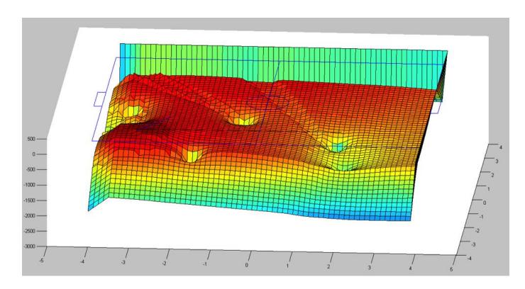
The current method of selecting the destination for a pass is evaluating the quality of the pass at all points on a grid, then choosing the position with the highest value. The function used for evaluating the pass quality relies on a few weighted predetermined features. Graphing these functions, as shown in Figure 6, reveals that they are for the most part continuous and smooth with few maxima; therefore, gradient ascent methods could prove to be very useful in finding optimal pass destinations by both decreasing the number of points to be evaluated while increasing the precision of evaluations.
In attempting to improve these functions and make them even more compatible with gradient approach methods, the pass quality calculations were revised to reflect the probabilities of both rewards and risks rather than arbitrary features. For an offensive pass. for example, the pass quality would reflect the chance of scoring and be determined through the probability of scoring if the pass is successful and the probability of an enemy interception. This could also enable the use of machine learning to adapt these functions during a game.
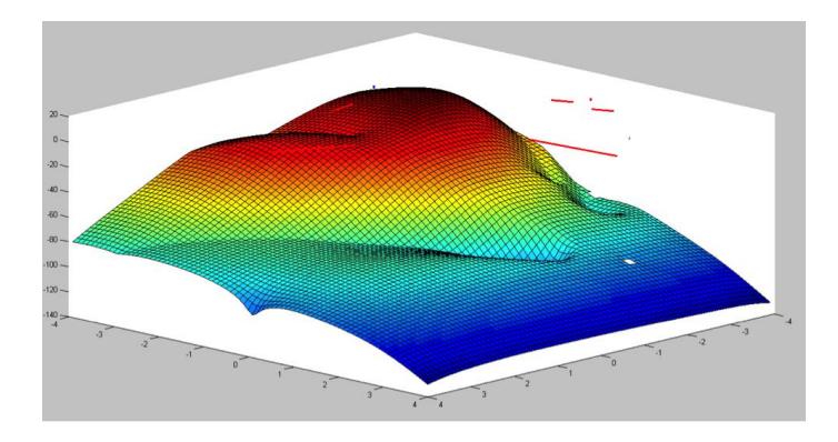
One of the issues encountered by this method is the occurrence of local maxima due to the blocking shadow cast by enemy robots. The function for determining the probability of enemy interceptions, as shown in Figure 7, will return near-zero values if the pass is directly blocked by an enemy, creating maxima on either side of the trail behind it. To resolve this issue, if an initial local maxima was found in close proximity to such a valley, a second evaluation would be run with the starting point being set on the other side of the valley. Prototypes of the gradient ascent algorithm reveal that it is able to find optimal values within seven iterations.
5 Conclusion
We believe that the design changes detailed above will lead to significant improvements in performance. We look forward to putting the changes into action at RoboCup 2015.
6 Acknowledgements
We would like to thank our sponsors, as well as the University of British Columbia, and specifically the Faculty of Applied Science and departments of Mechanical Engineering, Engineering Physics, and Electrical and Computer Engineering. Without their continued support, developing our robots and competing at RoboCup would not be possible.
References
- J. Fraser, S. Ghosh, C. Head, S. Holdjik, N. Jaques, A. Lam, B. Wang, A. Wong, and K. Yu, "2014 team description paper: Ubc thunderbots," 2014.
- A. Ryll, N. Ommer, D. Andres, D. Klostermann, S. Nickel, and F. Pistorius, "Mannheim team description for robocup 2013," 2013.
- B. Browning, J. Bruce, M. Bowling, and M. Veloso, "STP: skills, tactics, and plays for multirobot control in adversarial environments," Proceedings of the Institution of Mechanical Engineers, Part I: Journal of Systems and Control Engineering, vol. 219, no. 1, pp. 33–52, 2006.
- A. Andrew, "Another efficient algorithm for convex hulls in two dimensions," Information Processing Letters, vol. 9, no. 5, pp. 216 – 219, 1979.
- S. Baez, "Predicting opponent team activity in a RoboCup environment," ArXiv e-prints, Mar. 2015.