Description of the Warthog Robotics SSL 2015 Project
Rafael G. Lang, Alexandre M. Bernardo, Guilherme C. de Oliveira, Henrique B. B. Menezes, Leonardo C. Ramos, Leonardo G. S. Roque, Ivan N. da Silva, Roseli A. F. Romero
Warthog Robotics University of São Paulo at São Carlos
Abstract This paper presents the RoboCup SSL team WR Magic, developed since 2011 by the Warthog Robotics group from the University of S˜ao Paulo at S˜ao Carlos. This project merges the best features from older projects developed by the groups GEAR and USPDroids. The mechanical structure was upgraded to a new mixed design using aluminum and composite materials and contains four DC motors for locomotion. The system architecture is based on the GEARSystem library and presents a new fuzzy strategy decision module. The team presents full game capability with accurate and fast responses to strategy and referee commands.
1 Introduction
At the beginning of 2011 the groups GEAR and USPDroids merged creating the Warthog Robotics, a group of the departments of Electrical Engineering of the S˜ao Carlos School of Engineering and the Computer Sciences of the Institute of Mathematics and Computer Science of the University of S˜ao Paulo at S˜ao Carlos. The group counts with about 50 members students of Computer, Electrical and Mechatronic Engineering and Computer Science and develops robotics technologies, applying most of them at the robot soccer.
The mechanical structure and the electronic boards are the same from the last year and further description can be found in [1]. The next sections present some WR Magic features details, including the mechanical structure, electronic devices and computer systems.
2 Mechanical Structure
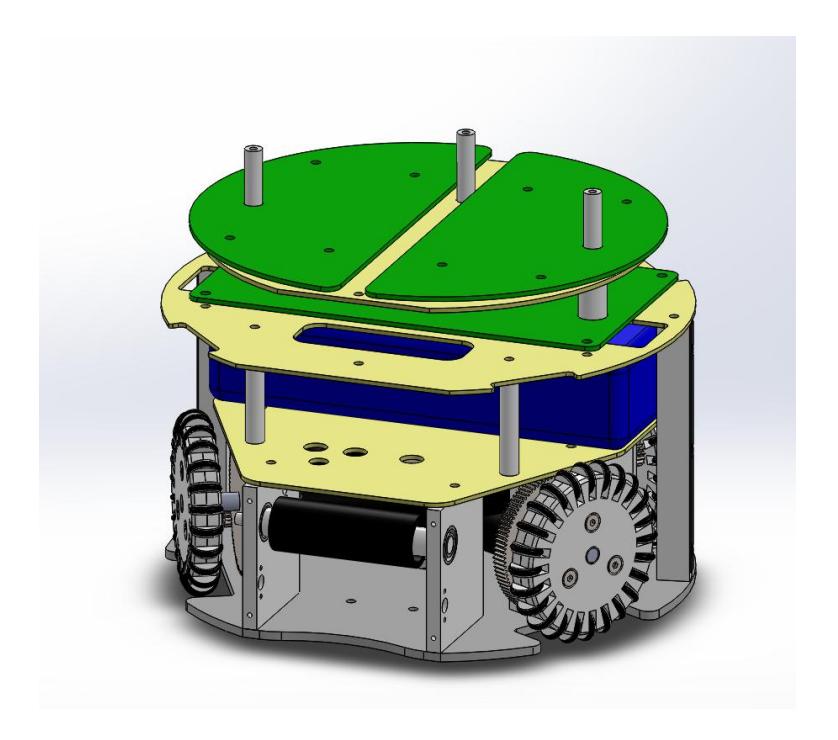
The mechanical structure of the robot was designed to accommodate the locomotion system, with its four Faulhaber 2342 DC motors, gearboxes of 6:1 ratio and 60 mm omnidirectional wheels, capable of providing a maximum speed of 4.5 m/s; the kicking device, consisting of two 2200 uF and 200 V capacitors and a custom solenoid with a concave plate attached to its axis, that can kick up to 8 m/s fast; and the dribble device that counts with a specific shape-roller coated with an viscoelastic material, mounted on a suspension with shock absorber system and linked to another Faulhaber 2342 DC motor by a 1:1 gearbox. The maximum ball coverage when dribbling is 18%.
The upper part houses the three electronic boards, the battery and the kick capacitor using glass fiber plates. The cover is a front cutted cylinder with protected wheels and oppenings for the kicking and dribble devices, resulting in a robot with 150 mm height and 179 mm diameter. All mechanical structure is made of aluminum and composite materials and was machined by the group members, offering a robust, yet light, robot that is shown in figure 1.
3 Electronic Devices
In order to fulfill the essential requirements of locomotion, kicking and dribbling, three electronic devices were developed: MainBoard, MotorBoard and KickBoard. The architecture of the embedded electronics is shown in figure 2.

3.1 MainBoard
The MainBoard is responsible for receiving commands from the artificial intelligence, decoding them and sending commands with SPI to the requested actuators (motors, dribble device and kick board). Moreover, it measures information as battery voltage and ball sensor status and sends them back to the telemetry system.
A dsPIC 33F running at 40 MIPS is used as the main controller: capturing the sensors, controlling the motors speeds, choosing the radio frequencies and controlling the other boards. The communication with the strategy is done by the transceiver nRF24L01+, a highly reliable module that runs at 2.4 GHz and implements features as address attribution, ShockBurst transmition mode and error detection via CRC [2].
3.2 MotorBoard
The MotorBoard receives commands from the MainBoard and controls the motor speeds. The control system must assure the proper functioning of the Faulhaber 2342 DC motors, therefore it counts with 512 lines per revolution Faulhaber IE-2 encoders to measure their real speeds, that act as the feedback of a classic PID controller.
The driving is done by two L298 ICs, activated by Pulse Width Modulation (PWM), for that is an easy to implement solution and, according to [3], ensures that "the global efficiency of the system, even when taking the losses due to harmonics into account, is much larger than the one provided by linear amplifiers". The control loop uses a PID control law with limits given by an analytical voltage and current estimator.
3.3 KickBoard
The KickBoard controls the kicking device, charging two 2200 uF capacitors to 200 V and discharging them in a custom solenoid when requested. The charging module follows the boost topology with a digital control system. A principle of the boost converter is the switching, in other words, there must be voltage/current pulses at the transistor gate, as described in [4], [5], and [6], hence a PWM signal is generated by another dsPIC33 circuit. Furthermore, an automatic stop system ceases the charging when the capacitors reach the wanted voltage and re-activates it when they fall under a certain value.
The shooting module consists of capacitor discharge and control module protection circuits. When shooting, the controller stops the charging and isolates both modules to avoid components damages, and the discharge circuit triggers a power transistor that lets the capacitors charge pass almost instantaneously to the solenoid. All boards are powered by a four cells LiPo battery of 2.6 Ah, that provides an autonomy of about 30 minutes to robot in a game-like ambient: with dashes, stops, kicks and dribbles.
4 Computer Systems
The WR Magic Project software is based on two sub-projects developed by the group: the GEARSystem library and the WRCoach strategy application.
4.1 GEARSystem
The GEARSystem is a distributed system library that provides communication among all system modules [7]. It is built over CORBA, a classic standard for this kind of application, and allows the execution of the AI application in one machine and the telemetry system in another one, for example.
The library architecture is minimalist, with four basic elements: Server, Sensor, Controller and Actuator. The sensors can create teams, players and balls and set their information (position, orientation, velocity, ...). Controllers may read these information and send commands to the actuators (move, kick, dribble, ...). Actuators read, decode these commands and execute them.
4.2 WRCoach
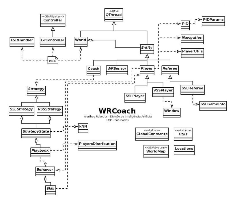
The coach is responsible for setting the strategy to the team. A small snipet of the software architecture is presented in figure 3.
The Strategy modules verifiy the state of the game and configure the a strategy state machine according to it. Each state of the machine is responsible for setting Playbooks and checking how are the robots positioned on the field.
The Playbooks take care of a number smaller or equal to the total of our robots in game. Each Playbook sets a Behavior for each robot and verify how the opponent team is performing on a smaller section of the field. Then, each Behavior is responsible for the actions of the robot, activating Skills according to how is the game near him.
The Behaviors act like a Skill state machine, changing states to activate specific Skills according to events of the game. Each Skill is a very specific set of instructions which are sent to the robot itself. The attribution is flexible: during the game, the strategy can choose the best set of playbooks, which, in turn, can choose the best set of behaviors for the game situation using a fuzzy control logic.
The path planning uses the orientated potential fields technique. This technique uses solutions of the elliptic partial differential equations contour value problem to create the potential fields. The Dirichlet contour condition was used [9], where the goals have potential 0 and obstacles, 1. This technique represents an evolution to the old USPDroids strategy system [10], because it allows the definition of behaviors at the generated trajectories. This is possible due to the definition of a influence vector to the potential field [8]. The utilization of this kind of equations also solves another conventional potential fields problem, the existence of local minimums.
5 Improvements for 2015
The mechanical and electronic projects are basically the same from 2014.
A new three-tier control model for the robot is under development with promissing preliminary results, with one controller for the robot's velocity, one for each motor and high-level one for the AI modules. In order to design a robust controller, complete models were created, considering several aspects of the robot's kinematic and dynamic. By the time of the writting of this TDP, the work is still in progress and shall have more details published as soon as the models are validated.
The presented WRCoach structure is completely new and allows more control over the AI componetns, facilitating the coding execution. Some legacy code was incorporated to the new one and went through an optimization stage for performance compliance.
6 Conclusion and Future Work
The presented project brings a whole set of improvements, taking the group to a highly competitive level. The developed hardware is robust, reliable and provides an excellent platform to the strategy systems. The implemented navigation algorithms allow the robot to move fast and softly in the field, permitting the execution of all desired strategies. Until mid-2015 the computer systems shall be tested harder and some new features may be available either on navigation and strategies or on integration systems, improving the ability of the team.
7 Acknowledgments
The authors would like to thank all Warthog Robotics team for the help and friendship; the University of S˜ao Paulo for the facilities and financial support; the Griffus, Embraer, Jacto, HOMIS, Arbor, Bauru Ferramentas and ALLTEC companies for the technical sponsorship; and all others that helped us during the project.
References
- Lang, R., Far¸coni, L., Santos, C., Oliveira, G., Barbosa, H., Pinto, A., Ito, F.: Description of the Warthog Robotics 2014 project. In: 2014 RoboCup (2014)
- Nordic Semiconductor: High Frequency 2.4 GHZ Wireless Transnciever. Data Sheet (2007)
- Olivera, V.A., Aguiar, M.L., Vargas, J.B.: Sistemas de Controle Aulas de Laborat´orio. EESC-USP, Brasil. (2005)
- Pressman, A.I.: Switching Power Supply Design. McGraw-Hill. (2003)
- Mohan, N., Undeland, T.M., Robbins, W.P.: Power Electronics Convertes Application and Design. Wiley (2002)
- Tse, C.K.: Complex Behavior of Switching Power Converter. CRC Press. (2003)
- Lang, R.G., Romero, R.A.F., Silva, I.N.:Olivera: Development of a Distributed Control System Architecture. In: 2014 Latin American Robotics Symposium. (2014)
- Prestes, E.: Navegação Exploratória Baseada em Problemas de Valores Contínuos. UFRGS. (2003)
- Smith, G.F.: Numerical Solutions of Partial Differential Equations Finite Differences Methods. Oxford University. (1992)
- Silva, M.O., Riveiro, M.V.F., Gaspar, L.S., Silva, W.C., Montanari, R., Romero, R.A.: Sistema do Time de Futebol de Robˆos USPDroids. In: CBR 2009. (2009)