Anorak Team Description Paper
Hamza Munir, Aamir Sheikh, Rana Shahid Ali, Amras Masood, Aaqib Mushtaq, Usman Malik, Faisal Muhammad Amin, Rafay Ishfaq, Danish Falak, Farman Ali
Anorak Artificial Intelligence and Controls, Center for Advanced Studies in Engineering, Islamabad, Pakistan
Abstract This year's paper describes the hardware improvements in gearing, addition of metal bases to the fleet and redesign of the acrylic omni-wheel. For ball actuation, a kicking device, dribbling unit and chipping device are also added. The software section describes our modular approach to multi-agent control and the use of a single radio channel for transmitting motion vector data to the entire team of robots. While keeping focus on developing low-cost platforms, the use of metal bases helps reduce hardware hurdles for software development. Hardware issues with gearing on acrylic bases are described in detail.
1 Introduction
Anorak's research is on multi-agent systems where individual members are aware of the circumstances the team is collectively working under. This includes acknowledging the deficiencies of underperforming members (due to technical faults and such), and taking appropriate measures to reduce the gaps in team performance caused by them. This involves modifying strategy and/or reprioritizing team objectives autonomously during run time.
Parallel to our research objective in artificial intelligence, Anorak builds robotic machines that are low cost, reliable and easily serviceable.
The 2016 RoboCup will feature our new robot design named "Athlete".
2 Team Targets
In terms of preparedness, our robots are in a much better position to perform in RoboCup matches. The team made important structural changes to overcome issues in the robot design intended for RoboCup 2015. Robots are now equipped with a working ball actuation system with kick and dribble capabilities. Adjustments to the dribbling unit are being made to improve performance. A chipping unit is in working order and installed, however it needs modifications in solenoid design to improve chipping force.
The targets this year in software are to have each robot processing unit at the server side run independently, and effectively coordinate strategy with its team members. However, the basic data filtering of SSL Vision packets and transmission of motion vectors to the robots is done by common modules to save computation resources and reduce redundant operations.
To evaluate software performance, data from the matches will be logged to our server and used for analysis. Software performance targets include having collision rates below 15% in all instances where collisions were possible, shoot on target rates of up to 67%, weighted against hardware shortcomings, and no more than 30% of zone allocation errors. The percentages are probabilistic estimates based on the software simulations of the zone allocation, shoot marking and collision avoidance algorithms.
3 Hardware
[Content in subsections]
3.1 Mechanical Design
The current summary of mechanical performance is given in the table below:
Table 1. Mechanical Information
| Max Mass | 1.8 kg |
|---|---|
| Dimensions | Dia: 178 cm; Height 145 cm |
| Centre of Gravity | Through central axis, 75 mm above ground |
| Max velocity | 3.5 m/s |
| Max Angular velocity | 8 rps |
| Acceleration | 4 m/s² |
| Ball coverage | 18% |
Robot weight has been reduced from 2.3kg to 1.8kg. The weight reduction is due to the revised design and also a switch from Nickel based batteries to LiPo packs. The kicker solenoid has also been reduced in size and the capacitor bank now consists of more compact capacitor elements than before.
3.1.1 Low Cost Strategies
Continuing with our experimentation with acrylic design, we have managed to improve performance while using the same materials and fabrication processes. Compared with metals and injection moulded plastics, the laser cut fabrication methods for acrylic take less time and keep costs low. This has allowed us to quickly test design iterations and is helpful in getting a larger number of design ideas experimentally evaluated.
The table below from our previous TDP outlines the cost comparison.
Table 2. Cost Comparison for Materials
| 6065 Aluminium | Cast Acrylic Sheet | |
|---|---|---|
| Density | 2.72 g/cm³ | 1.18 g/cm³ |
| Price per sq ft, 0.6 mm thickness | $3 | $3 |
| Fabrication cost per robot* | $250 - $300 | $14 - $25 |
*specific to the team's country of origin
The weight savings gained by using acrylic allows us to raise weight limits in components elsewhere, such as in the use of larger brushed DC motors. This reduces motor costs by over 24 times leading to massive cuts in per unit cost.
Table 3. Motor Comparison
| Maxon EC45 Flat | Johnson 550 | LDO 25 mm (geared) | |
|---|---|---|---|
| Cost per unit | $85.79 | $3.50 | $3.00 |
| Power | 30 W | 24 W | 20 W |
| Torque (Peak Eff) | 55 mNm | 62.4 mNm | 176 mNm (at wheel) |
| No load rpm | 4370 | 14500 | 400 (at wheel) |
| Weight | 75 g | 218 g | 180 g |
We have had a positive experience with using the Johnson 550 Motors. The use of brushed motors is by no means even comparable to Maxon's precision design and reliability, but provides an adequate cost effective alternative. The motors do use more battery resources and generate noise. However, the major drawback of these motors is the precious volume they take up in the already compact design.
The new metal bases are equipped with 25 mm brushed dc motors by LDO. Specifications of these motors are on the right hand column in Table 3. The motors provide better torque, but at the cost of maximum rpm. Given the availability constraints, these motors were the best option available. The motors do provide better efficiency because of a metallic bevel gearbox.
3.1.2 Mechanical Components and Descriptions
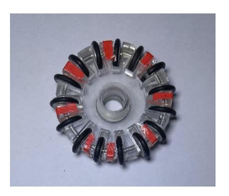
Wheels: The wheels underwent a thorough redesign because of a number of issues with the previous version. The O-rings on the rollers, in Image 1, were susceptible to premature wear and developed cracks. This was observed on reserve wheels as well. Secondly, the rims of the rollers would easily distort under acceleration causing the O-rings to slip out. At speed, this would cause severe imbalance to the robot and cause damage to the gears and motor shaft due to vibrations.
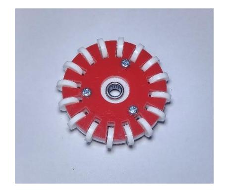
The new wheels feature acrylic rollers and a sturdier design. With a larger diameter of 60 mm and 16 rollers, the wheel provides higher top speed, better traction and allows us to put through more torque because a larger driven gear can be accommodated.
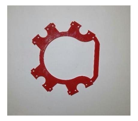
Images of the previous design and the new design are show below.

3.1.3 Performance results of acrylic gear design
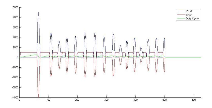
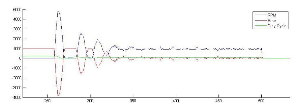
During the test runs for this year's qualification, we experienced issues with our acrylic gearing system at low rpms. While the gears perform well at higher speeds, the control at low speed is not smooth. This is because of the starting torque the purely perpendicular gears need in our assembly. The high starting torque required by the mechanism makes it difficult to maintain motor rpm at low speeds. The behaviour is visible in the telemetry results in figure 1.
3.1.4 Addition of Metal Bases
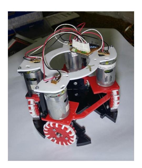
To avoid delays to our software development, the team procured metal bases as well. We have added 7 metal bases to our fleet based on the design shared by Skuba on their webpage. The specifications for these robots is given in the table below:
Table 4: Specifications of Metal Bases
| Robot Dia | 175 mm |
|---|---|
| Robot Height | 150 mm |
| Ball Coverage | 18% |
| Max. Velocity | 4.0 m/s |
| Weight | 2.3 kg |
| Kick Speed | 5 m/s |
Addition of the metal robots allowed practical testing of basic gameplay software which also improved the quality of our re-qualification video as the team was no longer limited because of hardware issues.
While we are continuing development of our low-cost platform, the metal bases provide a reliable backup where we can compete using traditional hardware.
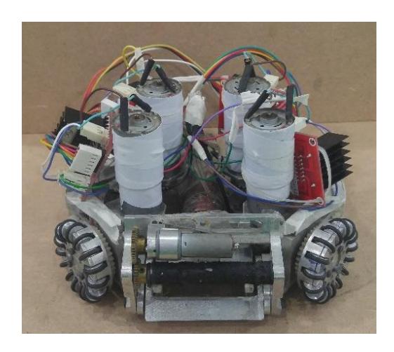
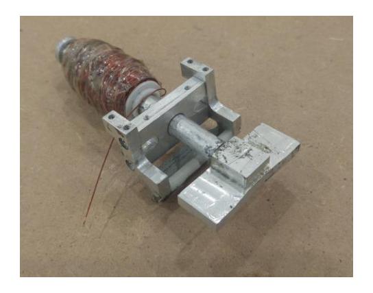
Both the metal and low-cost acrylic bases share the same embedded system, and boost and power circuitry. The robot base with the control circuit removed is shown in Image 5. An unmounted kicking device is shown in Image 6.
3.2 Electronic Components and Description
Most of the electronic components are same as last year. The summary of the electronic components from the last year's TDP is repeated below.
Main Processing Unit: For the main processing unit, each robot has an Arduino Mega 2560 R3 board. The board provides 54 digial I/O pins, 16 analog inputs and 4 hardware serial ports. The processor has a clock speed of 16 MHz.
Communication Module: We have opted for a 2.4 GHz radio transceiver which uses the nRF24L01 IC from Nordic Semiconductors. The choice was made because of the quick switching speed between transmission and receiving modes, allowing us to set up a two-way communication system with the robots. The chip also offers better transfer rates and extremely low errors. As compared to other modules, the low cost of the nRF24L01 chip makes it easier for us to keep costs low.
Motor Drivers: Each motor is driven by a L298N dual full-bridge driver by STMicroelectronics. The four ICs are mounted together with a cooling fan. This allows us to operate the motors at higher currents for longer periods of time. Each motor driver receives PWM signals from the main CPU. The CPU manages feedback control via a PID implementation.
Wheel Encoders: Each wheel axle has a slotted spinner. A mounted slot sensor detects the slots and sends input signals to the CPU via a signal amplifier. The count signals are used to determine the rpm of the wheels and is used for PID control of the motors. On our metal bases, we are using US Digital's E4P optical encoders.
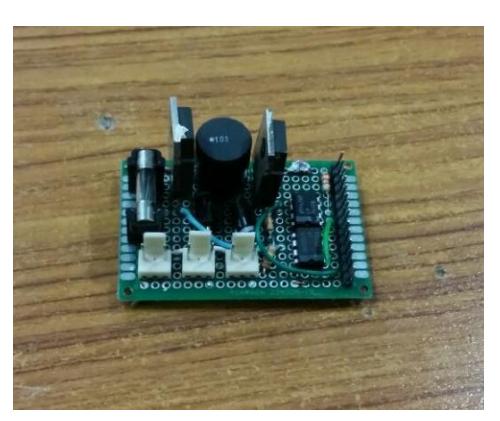
Kicking Circuit: The kicking circuit uses a capacitor bank of 4400 µF which is charged using a booster circuit. The CPU controls the discharge trigger through a transistor circuit. Charging takes around 2 to 3 seconds depending on configuration.
4 Software
Our software approach is covered in detail in our previous TDP. In this paper we provide a description of the software used in our qualification video.
4.1 Robot Processing Module
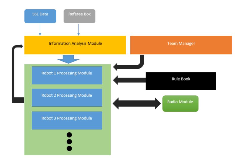
At the server side, each robot runs on a separate instance of the Robot Processing Module. The basic version of the processing module running in the qualification module contains solo play functions only. For example, the defender only functions as a defender and does not coordinate with the keeper or other robots for optimum placement and management. These features of coordination and strategy of the Robot Processing Module are being added currently. Figure 3 shows the current high level architecture at the server side.
4.2 Radio Protocol
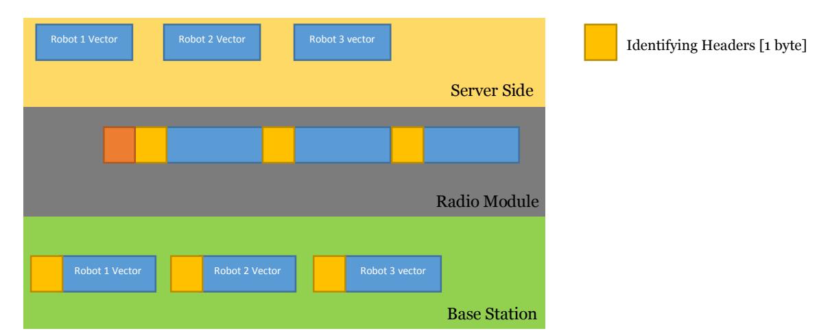
On the server side, each robot processing module generates a motion vector for the robot it is controlling. Each motion vector is 3 bytes long.
The radio module receives motion vectors from all robot processing modules and orders them into a single message, with identifying headers for each robot. In Figure 4, the Radio Module layer shows the data assembled into one message with headers separating each motion vector segment.
This message is transmitted serially to the base station controller. The base station controller uses the identifying headers to split the single message into individual messages for each robot, visible in the Base Station layer of Figure 4. Each message is then transmitted via an NRF chip using a single pipeline. The robots distinguish their motion vector from the others using the identifying header in each message.
5 Results and concluding statements
The inclusion of the metal bases allowed us to continue with our software development while we make improvements to the acrylic design. It also allows us to have a reliable backup fleet for RoboCup.
Gearing issues in our acrylic design have been a continuous hurdle in software testing. The metal bases procured by the team were modified to use low budget motors and a custom gearing design as well. This reduced the budget required to make the robots while giving us better reliability. However, because of the vertical mounting of brushed dc motors, the perpendicular gearboxes still reduce efficiency. But with the cost of upgrading to brushless motors out of reach, the solution currently employed by the team is the most suitable.
On the software side, performance of the modular AI design has been promising and did not present any major issues. Interfacing the separate modules on a single base station transmitter was a challenge though. The method described in section 4.2 provides a reliable solution. There were no major delays or framing errors when being used for up to 4 individual robot processing modules. As the complexity of the algorithm increases during the next stages of development, the radio protocol will need further modifications to cater for varying processing times of each robot processing module.
References
- Cauchy, Augustin (1847). Méthode générale pour la résolution des systèmes d'équations simultanées. pp. 536–538.
- Mordecai Avriel (2003). Nonlinear Programming: Analysis and Methods. Dover Publishing.
- Arduino Electronics Prototyping Boards: http://arduino.cc/en/Main/ArduinoBoardMega2560
- Ross, I. M. A Primer on Pontryagin's Principle in Optimal Control, Collegiate Publishers, San Francisco, 2009.
- Ohlmeyer, E.J., Phillips, C.A., Generalized Vector Explicit Guidance Journal of Guidance, Control, and Dynamics 2006; 0731-5090 vol.29 no.2 (261-268)
- Survey of Numerical Methods for Trajectory Optimization; John T. Betts Journal of Guidance, Control, and Dynamics 1998; 0731-5090 vol.21 no.2 (193-207)
- Kalman, R. E. (1960). "A New Approach to Linear Filtering and Prediction Problems". Journal of Basic Engineering 82 (1): 35–45.
- Wan, Eric A. and van der Merwe, Rudolph "The Unscented Kalman Filter for Nonlinear Estimation"
- Minsky, Marvin (1967). Computation: Finite and Infinite Machines. Englewood Cliffs, N.J.: Prentice-Hall. ISBN 0-13-165449-7.
- Aamodt, A. and Plaza, E. (1994). Case-based reasoning: foundational issues, methodological variations, and system approaches. AI Communications, 7(1): 39-59.
- Bacchus, F. and Grove, A. (1995). Graphical models for preference and utility. In Uncertainty in Artificial Intelligence (UAI-95), pp. 3-10.
- Nordic Semiconductor: http://www.nordicsemi.com/eng/Products/2.4GHz-RF/nRF24L01
- STMicroelectronics: http://www.st.com/web/en/catalog/sense_power/FM142/CL851/SC1790/SS1555/PF63147