NEUIslanders 2016 Team Description Paper
Prof. Dr. Rahib H. ABIYEV, Assoc. Prof. Dr. Irfan GUNSEL, Nurullah AKKAYA, Murat ARSLAN, Mustafa ARICI, Ahmet CAGMAN, Seyhan HUSEYIN, Fatih EMREM, Berk YILMAZ, Huseyin I. ERCEN, Gorkem SAY, Ersin AYTAC
Department of Computer Engineering, Near East University, Lefkosa, TRNC; Chairman of the Board of Trustees, Near East University, Lefkosa, TRNC; Department of Electrical and Electronic Engineering, Near East University, Lefkosa, TRNC; Department of Economics, Near East University, Lefkosa, TRNC; Department of Mechanical Engineering, Near East University, Lefkosa, TRNC
Abstract This paper describes a detailed description of NEUIslanders robotic team of small size league in RoboCup 2016. The important parts of mechanical, electronic and software design are described. The Robots are designed under the RoboCup 2015 rules. The improvements that have been done on robots are presented. These are related to the change and new design of electronic design of kicker system and improvement of navigation system of robot.
1. Introduction
NEUIslanders is an interdisciplinary team of students at Near East University. The team has been attending to RoboCup events since 2012, and currently seeking qualification for RoboCup 2016. Since last year, tremendous developments had been made on the team of autonomous soccer playing robots. This paper is going to outline the progress in implementation of the current model of robots.
NEUIslanders robot system consists of three major components, which are; the robot hardware, electronics, and control software. First of all, hardware of the robots is going to be examined. Mechanical parts of robots are going to be illustrated, and basic mechanical components of the robots are going to be described in detail. Electronics section is going to follow the hardware section. Electronic design of the robots is going to be illustrated in details, and basic information on the working principles of the electrical parts is going to be narrating. Finally, implementation details of control software are going to take place in the software section. Software for decision-making system, path finding and motion control is going to be illustrated in this section.
NEU ISLANDERS Robot Specifications
| Specification | Value |
|---|---|
| Dimensions | φ178x145mm |
| Weight | 3200gr |
| Driving Motors | Maxon EC-45 Flat 30Watt |
| Driving Gear Ratio | 72:20 |
| Dribbler Motor | Maxon EC-16 15Watt |
| Dribbler Gear Ratio | 24:48 |
| Kick Speed | Up to 8m/s (electronically limited) |
| Communication | XBEE 1mW |
| Robot Speed | 3.5 m/s |
2. Mechanical Design
2.1. Chassis
During all these years in RoboCup, NEUIslanders has tried different materials for the chassis of our robots. However, robots always have face some problems such as; robot chassis bending and denting during games, training or transportation. Last year, the chassis material had changed to titanium but manufacturers could not supply it. That is why; steel alloy had been used instead of titanium. Since steel is a heavy material, chassis have been redesigned with weight reduction holes while considering the bending moments. Original wheel orientation with 45 degrees at the rear, and 33 degrees at the front wheels with respect to the horizontal axis has remained the same.
2.2. Motor Mounts
8mm thick 7075 aluminum have been used for the motor mount. To make more place for kicking and dribbling mechanisms, motor mounts have been design both left and right handed. Maxon EC-45 Flat with MILE Encoder type motor has been used, the motor has an electronical board. This board stays inclined to left on the left-handed mounts, and right on the right-handed mounts to save space from robots height. Different colours of eloxal coating on the motor mounts have also been used in order to make motor mounts more understandable while mounting them on the robot.
2.3. Cover
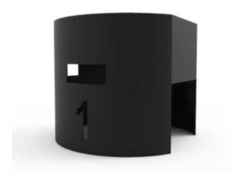
Previous years, metal based covers had prevent the communication with robots time to time. Since the field sizes gets larger, communication problem may become a much complex issue for the team. In order to avoid the communication problem, 3D printed robot covers from PLA plastic is going to be used. The robot cover is 2mm thick and in 220g weight.
3. Electronic Design
The electronic circuits of robots include main control units of wheel's motors, dribbler's motor and kicking mechanism. These control units include the main CPU, power supply circuit, wireless communication module, ball detecting circuit and dribbling motor controller, and motor driver. Previous year, design of the circuit protection unit had caused some issues during the event. In order to prevent any issues, this year, team had specially pay attention on protection units of the circuits, and successfully improves the design. New design had been tested and simulated on Proteus ISIS and ARES (Labcenter Electronics: Professional PCB Design and Circuit Simulation). Simulation and test results may be found below.
3.1 Voltage Boost Section
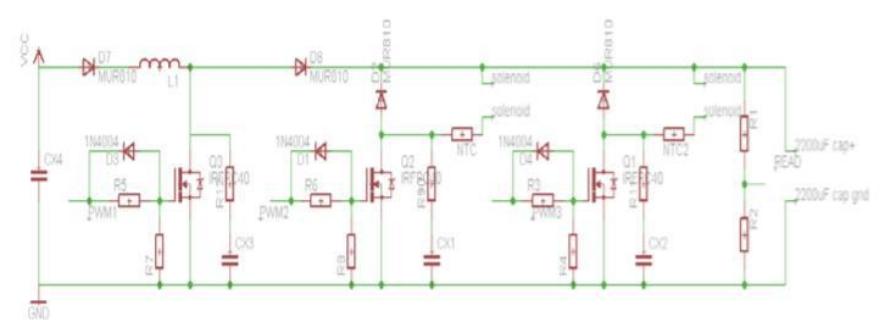
Robots kick movement had been provided by the solenoid. The energy required by the solenoid, to kick on the power required had been upgraded from 12V up to 240V. In other terms, robots now have booster circuit. Logically, booster circuit is based on step-up converter (boost converter). Step-up converter is a converter with an output voltage higher than its input voltage. The main principle that drives the boost converter is the tendency of an inductor to resist changes in current by creating and destroying a magnetic field. In boost converter, the output voltage is always higher than the input voltage. Boost converter schematic may found in the Figure 2 below:
When the Q3 is closed, electrons flow through the inductor (L1) in clockwise direction and the inductor stores some energy by generating magnetic field. Polarity of the left side of the inductor is positive. When the switch is opened, current will be reduced, while the impedance will be increased. The magnetic field that had been previously created will be destroyed to maintain the current towards the capacitor (as the MOSFET is rapidly turned off, the sudden drop in current causes L1 to produce a back e.m.f in the opposite polarity to the voltage across L1 during the on period to keep current flowing. This results in two different voltages, which are; the supply voltage VIN and the back e.m.f. (VL) that across L1 in series with each other). Thus, the polarity will be reversed. As a result; two sources will be in series causing a higher voltage to charge the capacitor (2200uF 250V) through the diode D8. If the switch had cycled fast enough, the inductor will not discharge fully in between charging stages, and the capacitor will always see a voltage greater than that the input source alone, when the switch is opened. Also while the switch is opened, the capacitor will be charged to this combined voltage.
When the switch will get closed, the right hand side is shorted out from the left hand side. Therefore, the capacitor will be able to provide the voltage and energy to the load. Meanwhile, the blocking diode prevents the capacitor from discharging through the switch. The switch should be opened again fast enough to prevent the capacitor from discharging excessive amounts.
Two resistors had been used (R1 and R2) to control capacitor voltage. The voltage between R1 and R2 had read via Atmega328P analogue input. When the voltage is equal to 240V, the charge circuit stops charging.
When the solenoid will be triggered, the Q2 or Q1 (depend to solenoid type that may be identified as; chip kicker or main kicker) should be closed. Afterwards, the charged capacitor will start to discharge toward to the solenoid and the solenoid will be kick. In order to protect the circuit, several measurements had been taken. R9, R11, R12, CX1, CX2, CX3 are protecting MOSFET and IGBTs. R5, R6, R3 have used for gate current limiter. D3, D1 and D4 discharge the gate capacitances bypassing the gate resistors and reducing the turn off time of MOSFET and IGBT. D8 prevents the capacitor from discharging through the switch. NTC is limiting inrush currents. R7, R8 and R4 prevent false triggering the MOSFET or IGBT.
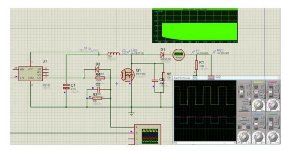
The circuit test and simulation was performed in Proteus ISIS circuit simulation. As the Figure 3 illustrates, arduino uno connected to the simple circuit. The IR2106 is driven from digital pin 11 and voltage is read from Analogue pin A0. This year, autokick have also been added to robots. Infrared emitting diode and silicon npn phototransistor have been used. The phototransistor's pins are connected to the analogue, 5V and gnd pins. Infrared emitting diode's pins are connected to the digital and gnd pins.
3.2 Circuit test and simulation
The simulations and tests played a significant role on observation of mistakes, disadvantages, advantages, values and results, and improve the design. The circuit had been tested and simulated in Proteus ISIS and ARES applications (Labcenter Electronics: Professional PCB Design and Circuit Simulation). Tests also shows currents, voltages, signals, and other variables in real time. Proteus's wide library and options provides easy design and results to its users. On the other hand, CadSoft Eagle that provides easier design abilities have been used to draw PCB design.
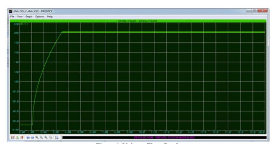
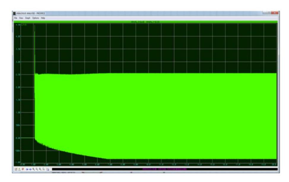
Figure 4 demonstrates the voltage-time graph. The voltage-time graph shows that the capacitor may easily be charged up to 200V in 3 seconds. Then the charging is stopped and fixed. Figure 5 demonstrates the current-time graph. The current denotes the inductor current. The maximum current is approximately 4.5A and the average current is approximately 2.4A. Figure 3 shows the PWMS for switching the MOSFET or IGBT. Signal, voltage, and current may clearly be seen in real time.
3.3 Motor Control Section
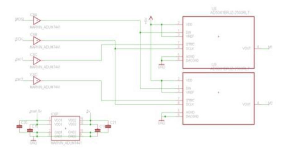
The motor and Digital to Analogue converters had worked flawless previous year. Therefore, the team did not need to go any changes on motor and Digital to Analogue converters this year. However, in order to prevent any possible issues, protection had been improved. DACs had been separated from main circuit with digital isolators. The AduM is digital isolator based on the analog devices. Combining high speed CMOS and monolithic air core transformer technologies, these isolation components provide outstanding performance characteristics superior to the alternatives, such as optocoupler devices and other integrated couplers. The connection of DAC and digital isolator had been illustrated below as Figure 6;
4. Software
This past year, software team has focused on four areas, which are;
- AI Bug Fixing
- New Firmware
- XBee Autoscaling
- Coexisting with other teams
On the AI side, most time had spent on bug fixing such as;
- Improving path finding
- Better ball merging
- Making sure all settings can be updated without software restart
- Updating all third party dependencies to their latests versions
The AI system is based on the concept of Behaviour Trees. One major overhaul was to add a new behaviour tree node called "throttled-action", which executes its children at a pre-set frequency. By this method, it is possible to reliably tell how fast a branch of the tree will execute and also removes the need to explicitly delay when writing game logic and provides uniformity. For example; all interrupter branches run at 50Hz or all radio communication branches run at 30Hz.
The firmware has been written from scratch, all blocking calls have been removed which caused timing issues with the electrical circuit. Two-way communication had also been added. Robots broadcast their state information every 50ms, which includes;
- Motor States
- Kicker charge
- Spinner state
With the state information team now have a reliable way to tell if commands send by the AI are actually processed by the robots or not. For example; a drop in charge after a kick command means robot have achieved a successful kick otherwise re send the command until the charge drops, same goes for the spinner.
Previously, single XBee radio was used to communicate with robots. This way of communication only allows one-way communication from AI to robots due to bandwith limitations. While single Xbee radio communication was working on movement, it creates problems for kicking and spinner control, because there was not any information provided if that command actually transferred to that individual robot or not. The old scheme was sending kick and spinner commands multiple times.
This year, new firmware broadcasts state information every 50ms using that information we've implemented a scheme that allows us to use any number of XBee radios. Whenever a new serial device that is receiving broadcast data is connected it will be pinned to robot IDs.
This scheme will automatically scale to any number of XBees upto 1 XBee channel per robot (or the old scheme 1 XBee channel for the whole team) without any configuration change. This will also allow the user to swap radio modules at will depending on the condition. For example; move robots that are less likely to kick to congested channels. The team has also been working on an experimental branch that attempts to assign robots to positions by taking in to account the link quality using checksum errors, more checksum errors equals less important spot on the field.
One major problem that the team had faced during the actual events was sharing the field with other teams during practice sessions. The software used to made some assumptions such as if NEUIslanders are playing blue, all blue robots belongs to them. This was problematic when the other team was testing with blue or when the vision system sees robots with blue markers on the sides. Since the new firmware broadcasts state information back to AI, it is possible to tell which robots are active without relying on vision information. New interface have been implemented for the AI system to query active robot IDs, and switching between vision information and radio information via the GUI have been provided. Having multiple balls on the field had also caused problem previous year. Assumption had been made based on 'all the balls on the field is up for grabs'. Simple heuristics had been used to reduce the ball count to a single ball, and then play using that. However, this caused problems when the AI selects other teams' ball as the primary. This year, simple filter have added to filter the data coming from SSL-Vision that will remove any ball that is not on home's side of the field (depending on the home goal setting). So, the AI does not know about any balls that are not on our side of the field.

References
- Rahib H. Abiyev, Nurullah Akkaya, Ersin Aytac. Navigation of Mobile Robot in Dynamic Environment. IEEE CSAE 2012 Conference, China
- Rahib H. Abiyev, Nurullah Akkaya, Ersin Aytac, Mustafa Arici, Muhlis Bayezit. NEUIslanders Team Description Paper 2012 , Robocup SSL, MexicoCity, Mexico
- Rahib H. Abiyev, Senol Bektas, Nurullah Akkaya, Ersin Aytac. Behavior Tree Based Control of Holonomic Robots . International Journal of Robotics and Automation. WSEAS Conference 2013, Limasol, Cyprus
- Rahib H. Abiyev, Nurullah Akkaya, Ersin Aytac. Control of Soccer Robots Using Behaviour Trees . ASCC 2013
- Rahib H. Abiyev, Senol Bektas, Nurullah Akkaya, Ersin Aytac. Behavior Trees Based Decision Making for Soccer Robots. Recent Advances in Mathematical Methods, Intelligent Systems and Materials 2013
- Rahib H. Abiyev, Nurullah Akkaya, Ersin Aytac, Dogan Ibrahim. Behavior Tree Based Control For Efficient Navigation Of Holonomic Robots . International Journal of Robotics and Automation
- Ali Erdinc Koroglu, Rahib Abiyev, Nurullah Akkaya, Ersin Aytac, Mustafa Arici, Kamil Dimililer. NEUIslanders Team Description Paper 2013 , Robocup SSL, Eindhoven, Netherlands
- Rahib H. Abiyev, Nurullah Akkaya, Ersin Aytac, Irfan Gunsel, Ahmet Cagman Improved Path-Finding Algorithm for Robot Soccer. International Conference on Control, Robotics and Informatics. Hong Kong 2014
- Rahib Abiyev, Nurullah Akkaya, Ersin Aytac, Gorkem Say, Fatih Emrem, Mustafa Arici. Team Description Paper 2014 , Robocup SSL, João Pessoa, Brasil
- Prof. Dr. Rahib H. Abiyev, Assist. Prof. Dr. Irfan Gunsel, Nurullah Akkaya, Murat Arslan, Mustafa Arici, Ahmet Cagman, Seyhan Huseyin, Fatih Emrem, Gorkem Say, Ersin Aytac. Team Description Paper 2015, Robocup SSL, Hefei, China