RoboDragons 2016 Extended Team Description
Yusuke Adachi, Hiroyuki Kusakabe, Naoto Tsuzuki, Hiroto Hayama, Daiki Yamaguchi, Masahide Ito, Tadashi Naruse
Aichi Prefectural University, Nagakute, Aichi 480-1198, JAPAN
Abstract This paper describes a system configuration of RoboDragons 2016, Aichi Prefectural University's participating team for RoboCup Small Size League (SSL). On the robot hardware, we use the robots developed in 2012. The robots were improved in 2015; the radio system was changed from 2.4 GHz wireless LAN to 5 GHz, and the dribble device and chip kick bar were redesigned to make as strong a kick as possible. On the soccer program, the base program is the one developed in CMRoboDragons joint team in 2004 and 2005. After the end of the joint team, we are continuously improving the program by introducing our research results. We implemented a learning algorithm of opponents' behavior this year and describe it in this paper. The algorithm is based on the one proposed by Yasui et al [1] in 2013. The effectiveness of the opponents' behavior learning is experimentally shown.
1 Introduction
RoboDragons 2016 is the team of Aichi Prefectural University (APU), which will participate in the RoboCup Small Size League (SSL). The team started in 1997 as a joint team between APU and Chubu university; then the team name was Owaribito. In 2002, as each university became able to develop their robot system independently, we started a new team, RoboDragons. Since then, RoboDragons has been participating in the SSL, including a joint team venture in 2004 and 2005 with Carnegie Mellon University, CMRoboDragons. Our best record was the 2nd place in 2009. Other than that, twice finished in 3rd place (2007, 2014) and three times in 4th place (2004, 2005, 2013).
This paper summarizes the system configuration of RoboDragons 2016 and describes a newly implemented opponent-behavior-learning algorithm, which was proposed by Yasui et al in [1].
Our robots were developed in 2012 and introduced in the 2013 RoboCup world competition. Their description is shown in [2]. During these 3 years, in robot hardware, we have improved both the wireless communication system from 2.4 GHz to 5 GHz to avoid frequency interference and the chip kick mechanism to stabilize the dribbling of the ball. In software, we have been continually improving. Last year, we introduced dynamic ball kicking and circle-and-pass motion [3]. In sections 2 and 3, we summarize our robots system.
Newly implemented into the software function is a learning algorithm of the opponents' behavior. The algorithm was proposed in 2013, however, it was not implemented until this year. In section 4, we describe the algorithm and the experimental results in detail.
2 Robot System
2.1 Robot Hardware
The robots we use now in our laboratory are sixth generation robots. The major part of the robots was developed in 2012. Their main features are:
- Cylinder with dimensions of 125 mm in height and 178 mm in diameter.
- Weight : 2.3 kg.
- Maximum percentage of the ball coverage : approx. 18%.
- Motors: a 50 watt DC brushless motor for driving each wheel.
- Simple proximity sensor.
- Wireless LAN for communication.
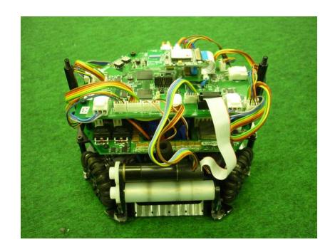
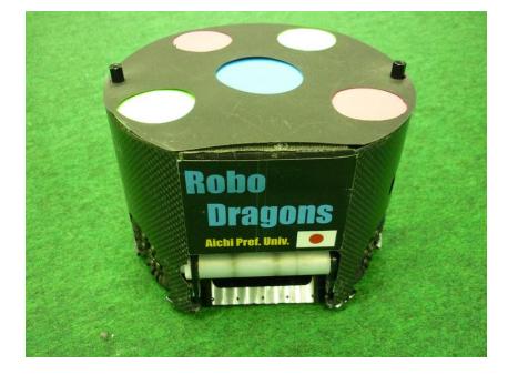
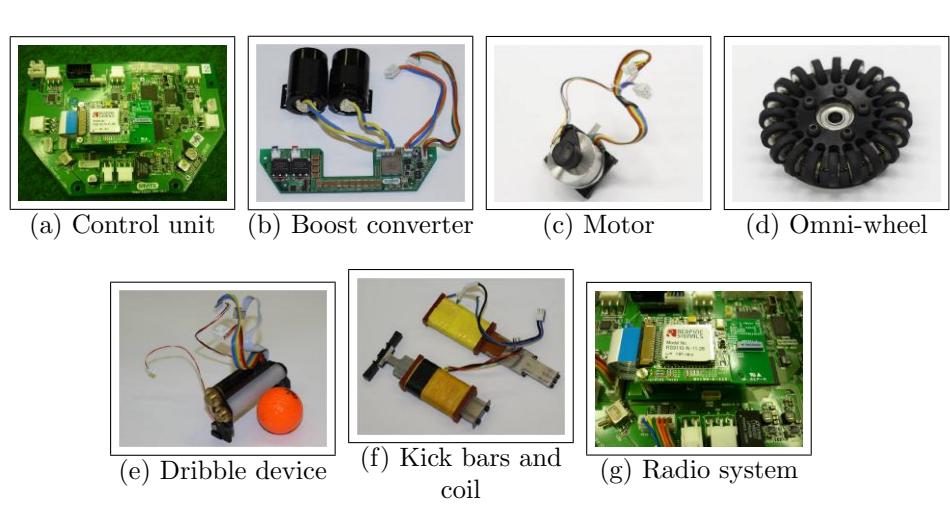
The robot is shown in Figure 1. Each component of the robot is summarized in Table 1 and shown in the photos in Figure 2.
Summary of the robots
| Device | Description |
|---|---|
| Control Unit | CPU: SH2A processor (Renesas Electronics Corporation) |
| operated with 196 MHz clock. Peripheral circuits (except | |
| analog circuits) are almost in the Xilinx's Spartan-6 FPGA. | |
| Boost Converter Convert from 18.5 V DC to 150 V - 200 V DC. | |
| Condenser has a capacity of 4400 µF. | |
| Charging time is about 2 s (when output voltage is 200 V). | |
| Motor | Maxon "EC 45 flat 50W". |
| Gear reduction ratio between motor and omni-wheel is 21:64. | |
| Wheel | 4 omni-wheels, each has 20 small tires in circumference. |
| Diameter: omni-wheel 55 mm, small tire 12.4 mm. | |
| Dribble Device | Dribble roller: 16 mm in diameter and 73 mm in length, made of |
| aluminum shaft with silicon rubber. Motor is Maxon "EC 16 30W". | |
| Ball Sensor | Infra-red light emission diode and photo diode pair. |
| Kicker | Kick bar is made of 7075 aluminum alloy. |
| Solenoid is a coil winding 0.6 mmϕ enameled wire. | |
| Straight kicker kicks a ball with over 8 m/s velocity at maximum. | |
| Chip-kicker kicks a ball as far as 4 m distance at maximum. | |
| Communication IEEE 802.11abgn 2.4/5 GHz wireless LAN. (New) |
2.2 Robot Control Program
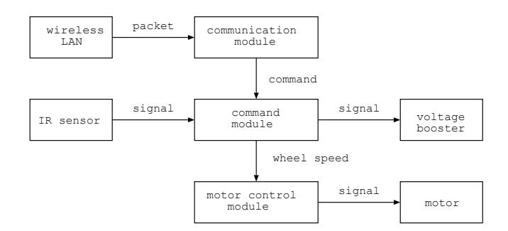
The block diagram of the robot control program is shown in Figure 3. In the figure, each box named module is a thread program which runs independently and other boxes are hardware devices which are controlled by the modules.
Robot command is sent from the host computer to each robot by the command packet (see next section) every 1/60 seconds through wireless LAN. The command packet is broadcasted to all robots.
The communication module receives the command packet and extracts the robot command of its own. If error is detected, the command is abandoned. Abandoning the command is a good option, if an error is not the burst error. Extracted command is sent to the command module.
In the command module, the velocity of each wheel is calculated from the robot velocity, moving direction and angular velocity values. The wheel velocities are sent to the motor control module. Moreover, the kick and dribble commands are executed in this module.
In the motor control module, the PID control is performed. This is done by using both the target velocity given by the robot command and the current velocity calculated from the encoder pulses. The PWM control is used for the motor driving.
3 Software System
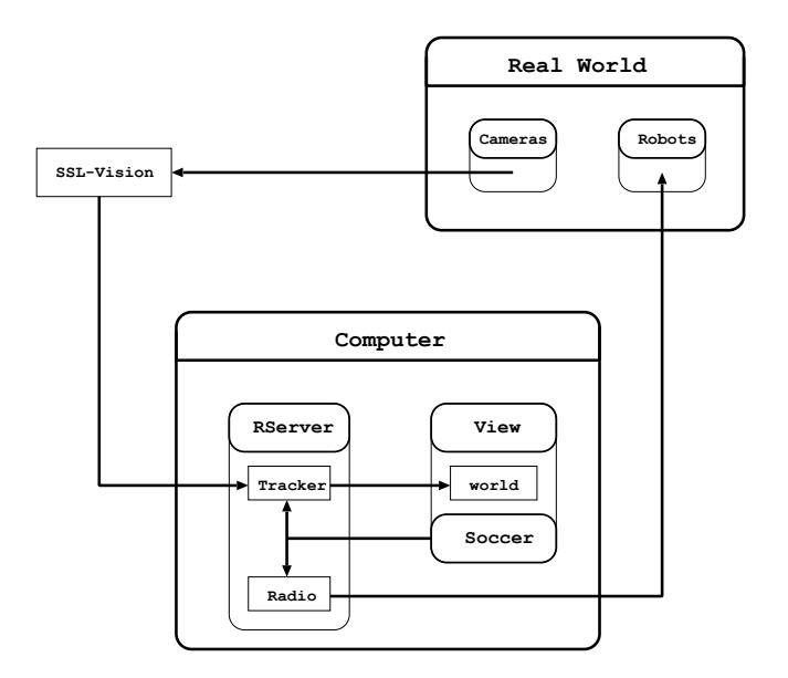
In this section, we show how our software system in host computer is composed and relates to the information from real world. The overview of our software system is shown in Figure 4. The host computer is an off-the-shelf notebook computer. The CPU is Intel(R) Core(TM) i7 4700MQ and the main memory is 4 GB. The operating system is the Linux (Ubuntu 14.04).
Our software system is divided into three main modules (Fig. 4):
(1) The Rserver module receives the data sent from the SSL-Vision system and compensates the positions of the ball and robots by using the Kalman Filter which is in the tracker submodule. Compensated positions are stored in the world block in Fig. 4 as the world data, which are shared with the view and soccer modules. The Rserver also sends the command packet to each robot through the radio submodule.
(2) The View module is a graphical user interface module. It displays the current soccer state which the team operator wants to know, and takes commands from the operator. The software system has a soccer simulator so that the simulation result is also displayed by the View module.
(3) The Soccer module makes an action command for each robot. By using the world data, the module chooses the best strategy for the current situation, gives each robot a role to take under the chosen strategy, and calculates a moving path to perform the role for each robot.
4 Classifying Opponent's Behavior
We proposed a learning algorithm of opponent robots' behavior in 2013 [1]. In the algorithm, opponent's set plays are into the categories, each of which consists of set plays occurred under one strategy. We implemented the algorithm this year, and show the results of experiments in this paper.
4.1 On-line Classification of Set Plays
Based on the algorithm shown in [1], we implemented the following algorithm:
Step 1 Right after a restart command is issued from the referee box, a set of positions and orientations of opponent robots and the ball position is recorded for every 6 frames (1 frame = 1/60 sec) until the kick is taken.
Step 2 Decide a number of clusters by the modified version of Davies - Bouldin index [4], which is given by
$$K = \arg \max_{1 \le k \le N} \left{ \frac{W(k)}{W(1)} \le h \right}$$
$$W(k) = \sum_{i=1}^{k} \sum_{X_p, X_q \in C_i} d_2(T_s^p, T_e^p, T_s^q, T_e^q).$$
where, h is a threshold, and d² is a dissimilarity function given in [1]. For every 18 frames, a clustering computation is executed by using the recorded sets of data and a number of clusters K.
Step 3 A series of data recorded in step 1 is kept for further use of clustering computation.
Above algorithm is rewritten by a pseudo-programming language as follows,
/*Classifying Algorithm*/
1 for(s = 0; s < setplay num − 1; s + +) {
2 compute d² between current play and set play[s] }
3 do clustering by group average method and make a dendrogram
4 memorize the dendrogram
5 compute K in step 2
6 make K clusters from the dendrogram
7 get pass direction from the cluster current setplay belongs
where set play[ ] is an array of set plays and set play[s] has data consisting of the trajectory of each opponent robot (see step 1 of above algorithm), ball position and pass direction (symmetry is considered). Setplay num is the number of set plays executed so far (including current set play) and current setplay is the set play now doing (the same data structure as set play[s]).
With the above clusters obtained so far, when a new set play begins, clustering computation for the new set play also begins. When the new set play is clustered into one of existing clusters, an action to block the opponent action can be taken before the opponent kicks the ball. We implemented a counteraction program that is executed when the system learned the opponent actions. In the next section, we evaluate if it works well or not.
4.2 Experimental Results
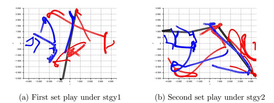
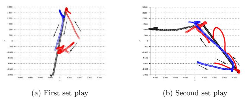
Assuming that the opponent action is occurred by turns under 2 strategies, we performed set plays and observed the change of actions. Figure 5 shows the traces of the teammate robots (blue), the opponent robots (red) and the ball (black). Fig. 5 (a) and (b) are actions occurred from 2 different strategies. We extract the primary robots from the figure and show them in figure 6. In the figure, an arrow shows a moving direction of a robot or the ball.
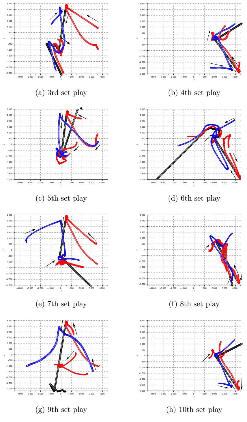
Applying the algorithm shown above, the system learned the opponent actions. Figure 7 shows a learning process. Traces of primary robots and the ball are shown in the figures. By the 4th set play, the system learned the opponent actions. So, 5th set play and after, our system can take a counter action.
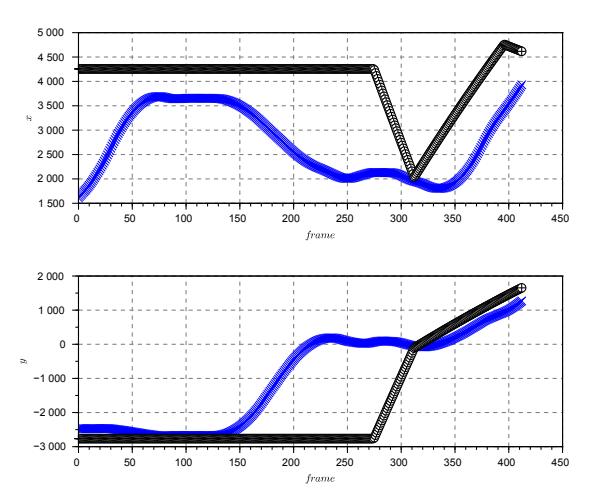
Here, we analyze the 4th set play in detail. As already shown, the clustering computation is executed every 18 frames. In the 4th set play, 7th clustering computation gives the correct clustering result. This means that 126 frames (= 2.1 sec) is necessary for getting the right clusters. The 4th set play takes 275 frames (= 4.5 sec) from the start of the set play to the kicking. Therefore, remaining 2.4 seconds can be used for the counteraction. Figure 8 shows the trace of a teammate's counteraction robot and the ball by time frame line. The upper figure shows x-coordinate and the lower shows y-coordinate. The figure shows that a counteraction robot blocks the ball at 310 frame (= 5.1 sec).
In the experiment, many set plays after 4th set play could take counteractions and block the opponent pass action. This shows that the effectiveness of the proposed learning algorithm.
5 Concluding Remarks
We showed the summary of hardware and software of RoboDragons 2016. Our advance this year is a learning of opponents' behaviors. we showed the learning process experimentally and the effectiveness of the method.
References
- Kotaro Yasui, Kunikazu Kobayashi, Kazuhito Murakami and Tadashi Naruse "Analyzing and Learning Opponent's Strategies in the RoboCup Small Size League", RoboCup symposium 2013, CDROM, 2013
- Kotaro Yasui, Yuji Nunome, Yusuke Adachi, Kengo Atomi, Masahide Ito, Kunikazu Kobayashi, Kazuhito Murakami and Tadashi Naruse "RoboDragons 2013 Team Description", http://wiki.robocup.org/images/0/0f/Small Size League - RoboCup 2013 - ETDP RoboDragons.pdf, accessed in 30/Jan/2016
- Yusuke Adachi, Hiroyuki Kusakabe, Yuya Yamanaka, Masahide Ito, Kazuhito Murakami and Tadashi Naruse "RoboDragons 2015 Extended Team Description", http://wiki.robocup.org/images/9/9e/Small Size League - RoboCup 2015 - ETDP RoboDragons.pdf, accessed in 30/Jan/2016
- David L. Davies and Donald W. Bouldin, "A Cluster Separation Measure", IEEE Transactions on Pattern Analysis and Machine Intelligence, PAMI-1(2), pp.224-227, 1979