RoboJackets 2016 Team Description Paper
Gabriel An, Justin Buchanan, Sean Csukas, Boris Iachonkov, Jonathan Jones, Jay Kamat, Ahmed Mansour-Elsayed, Andrea Mycroft, Sameer Naeem, Ryan Strat, Will Stuckey
Georgia Institute of Technology
Abstract The RoboJackets RoboCup SSL team was founded in 2007 and has competed every year since. The team's objective this year was to complete the new fleet of robots and associated software, that we began developing in 2014. This paper outlines further progress made on the robot design. We also outline improvements in our manufacturing techniques and software development workflow.
1 Mechanical
Mechanical improvements made from last year are described in this article. The Kicker-Chipper system was completely redesigned from last year, taking lead from Tiger Mannheim's design [1]. Testing was also done on damping dribbler where spring damping and spring-foam damping were compared. Lastly, efforts were made to initiate future plans for improvements to increase the functionality and improve the manufacturability of the robot.
1.1 Kicker-Chipper System
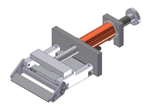
The new fleet of robots utilizes a combination of rectangular and cylindrical solenoids. Incorporating a rectangular solenoid helps improve space efficiency, allowing more room for other components such as a larger battery, as well as lowering the robots center of gravity. The 2016 design of the kicker-chipper system is mainly modeled after the design used by Tigers Mannheim [1]. The main advantage of their design is that the kicker-chipper system fits within a vertical range of approximately 1.25 inches, as compared to the RoboJackets' 2011 design which fit within 2.5 inches. It was adapted for the manufacturing processes available to the RoboJackets. The final assembly for the kicker-chipper can be seen on Figure 1. The wire used on the custom-made flat chipper solenoid is currently a 22 AWG magnet wire with 150 turns. The same wire will be used on the custom-made kicker solenoid, and the number of turns necessary will be determined after future trials.
The rectangular solenoid went through many iterations in order to reach its current design, which utilizes stock parts and water jetted acetal pieces in order to improve manufacturability.
1.2 Dribbler Damping
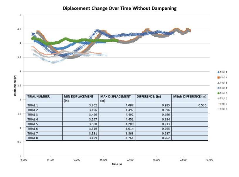
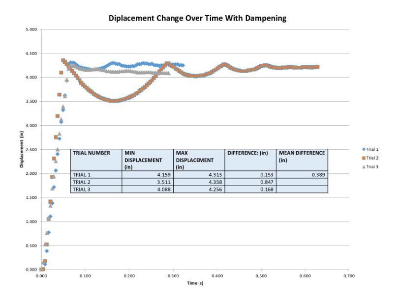
The damping system is designed to improve control over the ball. Catching a pass with a damping system, consisting of a single spring, causes the ball to bounce a significant distance, averaging about 0.530 inches from the robot, increasing the time until a maneuver can be made. Adding foam to the damping system helps dissipate more of the balls kinetic energy, decreasing the distance the ball bounces to an average of 0.389 inches after receiving a pass. The foam is made out of a pelican pick and pluck foam and it is placed within the coils of the spring, thus contributing to the damping effect. Figure 2 and Figure 3 show the data for the ball displacement over time. As can be seen from the data, the spring and foam combination produces the least bounce-back distance on average, reducing the time needed to recover from a pass.
1.3 Future Work
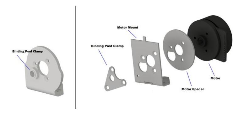
The driveplate design is critical to the performance of the robot, as the driveplate bears all of the robots weight. The design shown in Figure3-Piece Driveplate Design will have the advantage of being more space-efficient than the current one, since it is made out of steel and requires less material to be structurally sound under the given conditions. This design will also be better in terms of manufacturing speed, as it will requires only two operations: water jetting 2D profiles and bending those pieces. Accuracy in metal bending will be achieved through incorporating slots into the part profile, causing the stresses to concentrate on the bending line.
2 Electrical
The electrical team primarily focused on completing the 2016 set of boards. The kicker board was improved to allow for data collection to support future endeavors. The housing for the breakbeam mechanism was completely redesigned to improve robustness and accuracy. Additional firmware functionality was expanded to support all hardware devices on the robot.
2.1 Kicker Board
On the 2013 kicker board, the kicking and chipping were controlled directly from pins on the 2011 control board's microcontroller. To improve versatility of the interface, the dedicated lines were replaced with an SPI bus that connects with an Atmel ATtiny 84A microcontroller on the 2015 Kicker Board [2]. Although no additional functionality is gained from this change with the current implementation, the SPI link will allow for many hardware independent developments to be implemented. Future improvements will see the addition of detailed data collection and logging which will assist in debugging fault hardware.
2.2 Break Beam Boards
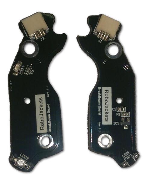
The standalone IR detector/emitter pair on the 2011 robot base was prone to misalignment and disconnection. The 2015 drive base and electrical system saw the development of a new board that exactly matches the contours of the robot's dribbler assembly. These custom boards provide a sturdy mount for the IR detector and emitter pair. The boards chosen are only 0.6mm thick to reduce space consumption and use black solder mask to reduce stray reflections around the detector. In the event of malfunction or damage, the boards can be swapped with the removal of only one screw. Four-wire flat flex cables are used to connect both the emitter and detector boards to the control boards. The designs for both the emitter and the detector boards are only one-sided PCBs. To reduce cost, every break beam board was manufactured with an emitter on the front and a detector on the back. During assembly, only one side of the board is populated.
Unique ID Chip
The unique ID (UID) chip that is discussed in detail in the Software section is located on the break beam board. This location was chosen to house the UID chip as it was identified as the board with the lowest failure rate. Each time a break beam board is swapped, it will be necessary to update the configuration file within soccer with the new mapping of the UID chip to the robot base.
2.3 Firmware
A new set of firmware was written for the on-board operations using the mbed and CMSIS-RTOS libraries [3–5]. This allows for easier hardware upgrades and optimizes resources for the on-board control loop. As a result, we have added an on-board IMU that is incorporated into the control loop between radio packets. This increases the previous control loop's frequency from 60Hz to now 240Hz.
The robot's FPGA was redesigned to include more robust motor fault detection. This information is retrieved by the control board and communicated to a user via onboard LEDs for instant feedback that the robot is inoperable.
3 Software
The software team mainly worked on firmware and radio protocol features for the 2016 robots. Robot-specific unique identifiers and tuning packets were added in order to support real-time updates of robot-specific motion control parameters. In addition, new continuous integration software was developed in order to better reflect development environments and lower time required to run the unit and integration tests.
3.1 Radio Protocol
The 2016 radio protocol adds several new features and future extensibility to fleet communications. The new protocol supports multiple packet types, allowing different information schemas to coexist. Since these types are identified in packet headers, we can amend or add information schemas in the future. Previously, all data was transmitted with unicast packets, thereby preventing common information from being distributed to all robots efficiently. In addition to unicast packets, the 2016 radio protocol supports broadcast packets - ones that are received and processed by all robots connected to the base station.
Fig. 6. The most common packet, the control packet, is used to send motion commands. The packet type ID, the first 4 bits, are common across all packets.
| Byte | 7 | 6 | 5 | 4 | 3 | 2 | 1 | 0 |
|---|---|---|---|---|---|---|---|---|
| 0x00 | MC (0) | Type (000b) | length | |||||
| 0x01 | Bits 07-00 of UID | |||||||
| 0x02 | X Velocity (09-02) | |||||||
| 0x03 | Y Velocity (09-02) | |||||||
| 0x04 | Angular Velocity (09-02) | |||||||
| 0x05 | Dribbler Velocity (09-02) | |||||||
| 0x06 | X Velocity (01-00) | Y Velocity (01-00) | Angular Velocity (01-00) | y | Dribble Velocity (01-00) | / | ||
| 0x07 | K/C Strength | |||||||
| 0x08 | K/C | K/C Arm | FW | Song |
3.2 Wireless Firmware Installation
The 2008 and 2011 fleet of robots have supported over-the-air firmware updates for many years. This feature greatly enhances the team's ability to ensure all robots are running the correct version of firmware. The 2016 fleet of robots is currently flashed by connecting a single robot at a time to a computer via USB. The MBED microcontroller requires firmware files to be stored on the filesystem flash storage, which is separate from the flash storage used during program execution. On boot, the mbed copies any modified firmware files from the filesystem flash to the processor flash.
Control packets first signal one or more robots to enter a state capable of receiving firmware updates. As firmware packets are received, the data is written to the mbed's filesystem flash. A checksum is used to ensure that firmware is not corrupted in transit.
3.3 Per-Robot Tuning
To compensate for the unique and subtle construction differences between robots, we now tune robot control parameters on an individual basis. In the past, motion control parameters were hard-coded into firmware and couldn't be changed in response to differences in mechanical bases. In the new protocol, bots are addressed by unique identifiers mapped to specific robot bases so that tuned parameters can be persisted. The extensible protocol supports live parameter updates via tuning packets. When parameters need updates, the base station sends a tuning packet and instead of a control packet. If multiple parameters require updates, several rounds of tuning packets will be sent. Tuning is expected to take place during testing and initial robot startup, therefore the drop in control resolution will not take place during or interfere with competition performance. Both control and tuning packets are sent addressed over unicast.
3.4 Continuous Integration
A major part of any software project is quality assurance. In a large software environment with many inexperienced programmers it is not uncommon for programmers to fail to properly test contributions. Our old continuous integration (CI) system ran on Travis CI and fulfilled all the basic requirements of any CI setup, such as automatically running tests, reporting on their results, and publishing documentation. However, it had a few crucial issues. The builds on this system took a long time, the results would be merged into a single indicator (making it hard to debug issues), and the build system ran on outdated software, requiring many workarounds.
Current Continuous Integration System
While more complex, our new CI system solves many issues present in the original setup. This was achieved with a Docker-based framework to run our tests. Docker creates a lightweight, isolated environment that is separated from the host system. With Docker, we were able to cache our dependencies, as well as create an isolated Ubuntu 14.04 system, cutting normal build times from about 30 minutes to under 5. In addition, this framework keeps track of each tests pass/fail status and displays it as a green check or a red x next to every commit on GitHub. The log of each test command is also captured and uploaded to a link, which makes it easy to quickly pinpoint the cause of failure. The ability to add individual isolated tests makes it simple to add style and coverage checking to our CI setup as well.
Initially our new CI system was tied to our project, but we have since separated it out into its own repository to make it easy for others to use. Because tests are run inside Docker, it makes it easy to reproduce any environment you wish, even a ROS system, which would normally be more difficult to create CI for. The CI framework can be found at https://github.com/jgkamat/docif.
Acknowledgements
William Chen, Jacob Chesler, Carissa Fernandez, Tingzhi He, Zhuo Ma, Roberto Medrano, Evan Peterson
References
- Tigers Mannheim RoboCup SSL Team. Extended tdp for robocup 2015. Technical report, Baden-Wuerttemberg Cooperative State University, 2015.
- 2011 control board. https://github.com/RoboJackets/robocuppcb/tree/master/archive-pcb/control-2011-c. Accessed: 2016-01-26.
- Cmsis-rtos api. http://www.keil.com/pack/doc/CMSIS/RTOS/html/index.html. Accessed: 2016-01-27.
- mbed api. https://developer.mbed.org/handbook/Homepage. Accessed: 2016-01-27.
- Robot firmware. https://github.com/RoboJackets/robocupsoftware/tree/master/firmware/robot2015. Accessed: 2016-01-27.