Small Size Holland Team Description Paper RoboCup 2016
Joost Overeem, Rimon Oz, Nanko Schrijver, Jeroen de Jong, Thomas Hakkers, Ryan Meulenkamp, Jelle Meijerink, Nick van Deth, Michel Teterissa, Sven Dickers, Emre Elmas, Mark Lefering, Rob van den Berg
Life Science, Engineering, and Design, Saxion University of Applied Sciences, M.H. Tromplaan 28, 7513 AB Enschede, The Netherlands
http://www.SmallSizeHolland.com/
Abstract This paper outlines the major design decisions, and implementation and test results by Team Small Size Holland since participating in Robocup 2015 in Hefei, China. Progress was made on the development of a new team of modular robots and significant steps were taken in redesigning the software with the goal of going open source right after Robocup 2016 in Leipzig.
1 Introduction
Small Size Holland (Team SSH) from Saxion University, the Netherlands, builds upon the ongoing research of previous years. This paper outlines the work since the the team's previously published paper [1]. In July of 2015 we started working on redesigning both software and hardware.
At the tournament in Hefei we played with our first generation of matchready robots. With the insights gained from the analysis of video material of the matches, we went straight back to updating the hardware of the robot and working on a rewrite of both the server- and robot-software. The new team of robots is expected to be fully assembled and ready to go by May.
This paper discusses the major changes in hardware and the software, including an overview of the strategy. Chapter two discusses the mechanical changes. The third chapter presents the new CPU and other electronical improvements. Chapter four describes the new software and a novel approach to SSL-strategy.
Besides the ongoing development of the robots, we have decided to open source all of the code and are in the process of getting the documentation in order. We expect this process to be done by July.
2 Mechanical Design
During the matches in Hefei, we realised that the previous generation of robots had issues with ease of maintenance. During the games there were quite a few broken motor-controllers and malfunctioning kicking mechanisms. Because of the way the robot was built these repairs were both time-consuming and expensive.
To solve both these problems we decided to modularize the robot; every part has to be easily replaceable in order to drive down expenses and hours of maintenance. To accomplish this, we decided to subdivide the robot into several areas: wheel modules, a chargeboard, a motherboard, a dribbler, a chipand-kick module, the hull, the battery and its socket, and wheel arches. All these parts can be replaced or removed individually. This will accommodate further research, since prototypes for new modules can be hotswapped without (partially) redesigning the robot. Downsides to this change are losing space for components and adding more weight to the robot.
2.1 Wheels
We have decided to move from a 3-wheel design to a 4-wheel design. Main reasons for this were the ease of controlling a 4-wheel robot and a better distribution of leverage for each wheel in all driving directions. This will prevent the robot from undulating and also result in a higher speed in desirable driving directions.
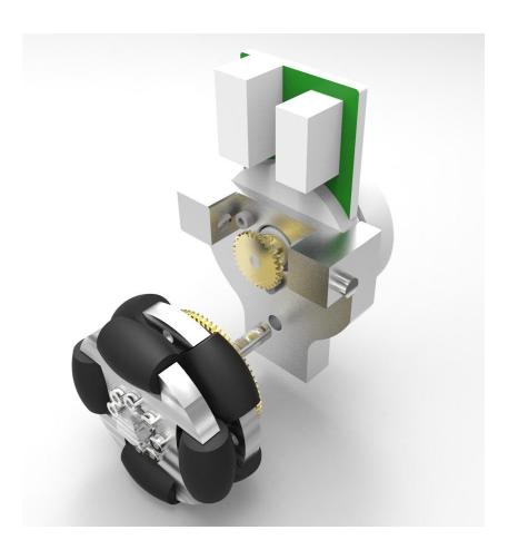
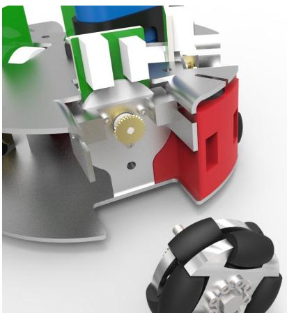
Wheels should have as much grip as possible to accelerate faster. The previous design used omni-wheels with cassette tape wheels as gear teeth to grip the grass. This approach did not work and as a side-effect the robot bounced up and down while driving. Our proposed solution is to use omni wheels that have a rounded rubber surface as shown in Fig. 1. The wheels are placed in such a way that the rubber is always touching the ground and the metal parts of the wheel don't cut into the grass. This idea was based on findings by Robert L. et al. [2]. Suitable wheels are available for sale on the internet.
To make it easy to disassemble the robot or change eg. the gear ratio, we made the wheel module a replaceable component like shown in Fig. 1a. The entire module can be replaced by removing two screws.
Also the shafts of the wheel were redesigned. The screws that were used before are now replaced by shoulder screws with proper bearings which allow the wheel to rotate with low friction. These shoulder screws make it possible to lock the wheels in place without jamming the bearings.
The last change that was made was the placement of the holes in the gears attached to the wheels. These were placed using a milling machine, this improved the positioning of the holes. The improvemed placement created a better connection between the gears. The new connection improves the lifespan of the gears as well as reducing the energy loss in the transmission.

2.2 Dribbler
The first team of robots we played with had fixed dribblers covered with an inner tube from a bikewheel. The dribbler is driven by a 944D Motor with a nominal rotational speed of 2000 rpm. During tests, and also the matches played, we found that the robots were not able to receive a pass properly.
Changes were made to the ball receiving mechanism to combat this. For instance, the springs which damp the dribbler have been replaced by weaker ones. This way the dribbler moves easier and can absorb more energy of the ball. These springs were attached using two shafts.
A new rubber was used to coat the dribbler. This rubber has a higher friction with the ball and is thicker than previously used rubbers. The increase in thickness increases contact time which can be used to absorb the forces of the ball. This reduces the bounce of the ball.
There has also been a change in bearing choice. This is due to the range of angular velocity of the motor. Its reachable velocity is 39300 rpm. The previous bearings had a maximal angular velocity of 4000 rpm, this created a huge bottleneck. Due to this difference, the bearings are replaced by bearings that can reach speeds of ten times higher. This way when the ball makes contact with the dribbler, the ball gets a backspin which makes the ball roll toward the robot.
To increase the likelihood of completing a pass, we designed a construction in which the dribbler depresses as the robot receives the ball. Our test set-up, shown in Fig. 2a, was able to receive a pass at a speed of $6\frac{m}{s}$. The design of the dribbler assembly, which is based on the test set-up, is shown in Fig. 2b. The current construction makes use of 90° torsion springs.
We also wanted to be able to control the rotational speed of the dribbler for performing moves such as a back heel, for gaining possession while turning around, etc. For gaining possession we need a better combination of grip and rotational speed than the opposition. Our solution for this is a new dribbler motor: an induction motor with a nominal speed of 39300 rpm. The specs of the old and new motor are shown in Table 1.
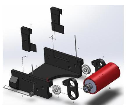

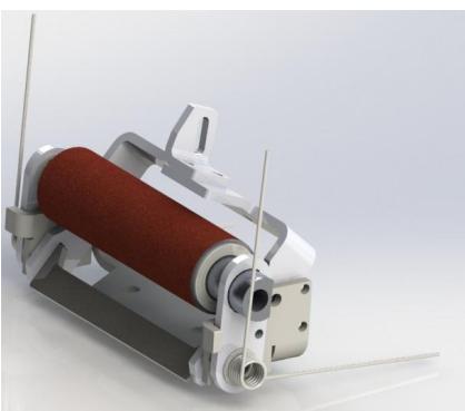
Table 1: Dribbler Specifications
| Specification | EC16 Motor | 994D Motor |
|---|---|---|
| Voltage (DC) | 12 V | 6 V |
| Nominal Rotational Speed | $39300 \ rpm$ | $2000 \ rpm$ |
| Torque | $7.85 \ mNm$ | 1.76~mNm |
2.3 Solenoids
The design of the solenoids has been changed to optimize the use of space within the robot. The lower solenoid has changed to an oval shape, due to this flat and wider form, the solenoid can fit in the robot and makes the best use of the available space. The lower solenoid can be described as a tube pressed fitted between the front and back of the solenoid. Around this tube, the coils of the solenoid are wound around the tube. To create an easy accessible path for the flux lines, an iron sheet metal hood is placed over the solenoid, in this sheet metal is attached to the lower solenoid as well as to the upper solenoid. The lower solenoid is used for kicking whilst the upper solenoid is used for chipping.
3 Electrical Design
Our previous charge board had a few issues, and with the redesign of the frame, we decided to do a redesign of the circuit. The charge board is now combined with the switch board (the board in our previous design containing the MOSFETs). The board is better fused and is now situated separately from other electronics. The charge board is placed in the center of the robot in order to increase the safety for people handling the robot.
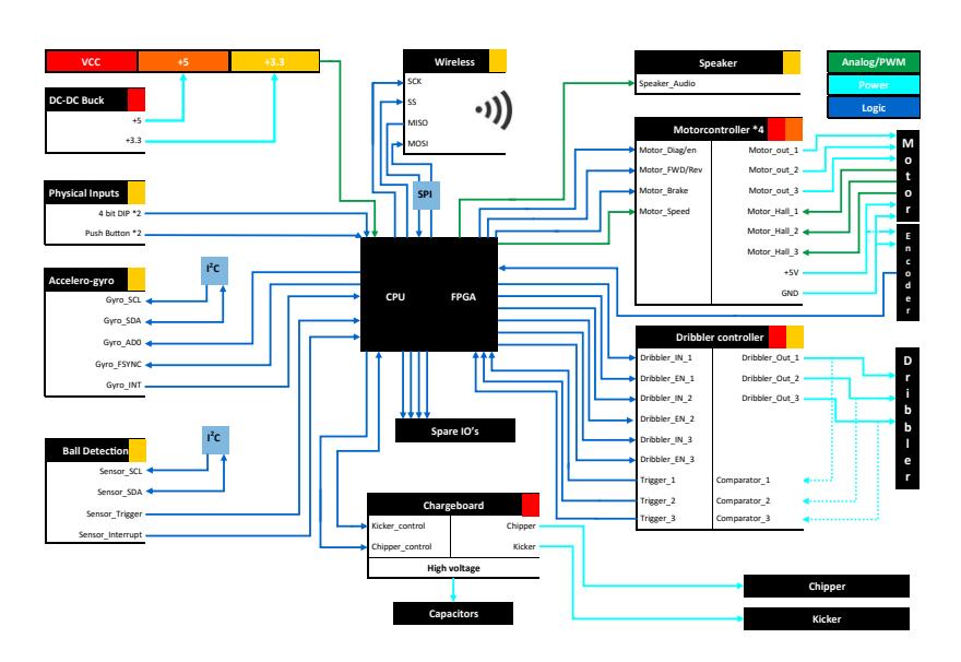
The motherboard also contained a few mistakes, so we made a redesign of the motherboard as well. Most of the proposed functionality would be covered by a new and powerful CPU, described in Paragraph 3.1. Furthermore, there were two new motor-controllers which had to be added: one for the extra wheel and one for the new dribbler motor. Lastly, we decided to integrate a few new sensors. All these subsystems are on the motherboard and their connections to external components are shown in Fig. 3.
3.1 CPU
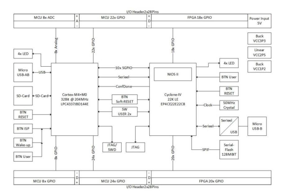
The previous generation of robots had an MBED as processor. The MBED is a single-core ARM Cortex-M3 processor. To make the robot act fast on its sensors and network data the new robots need more processing power. A new processor has been chosen, this is an LPC4337JBD144 microcontroller. It contains two cores; a Cortex-M4 core with a FPU (Floating Point Unit) and a Cortex-M0 coprocessor. This makes it possible to process a variety of data from several sensors and the WiFi chip.
Because there is latency between the robot and the server, the robots should be able to make small movements autonomously. For guidance of these small autonomous movements an accelerometer, a gyroscope and motor position encoders are used to monitor the movements of the robot.
In order to keep the robot as modular as possible, a pluggable unit (similar to the MBED) is used which can be plugged into the motherboard. For the real time regulation of the motor controllers an FPGA (Cyclone IV EP4CE22E22C8) a is integrated in the system, the result is a hybrid processor unit. The FPGA is connected to the microcontroller with 10 SGPIO lines in order to communicate fast with each other, as show in the system diagram in Fig. 4.
3.2 Robot communication
In our first design the most obvious method of data transmission was chosen based on research done previously in SSL, but there was no in-house research done on alternatives. This year we did research on what method of communication is better suited. For the method of data transmission and a suitable chip, the most important requirements of the communication were: support for protobuf, reliable data transmission, and low latency. Minor requirements we had were the use of standard equipment and the possibility of updating the robot software via the wireless communication.
Wi-Fi doesnt need a separate base station, such as the one needed for the NRF, because the server has a Wi-Fi card. Also, Wi-Fi makes it possible to easily flash new software on the robots OTA. The data loss caused by a crowded 2.4Ghz band is not expected to give issues since the system with the NRF chips were also 2.4Ghz. Based on these advantages, we decided to switch to Wi-Fi given it could provide enough performance. The router is a standard piece of equipment that allows drop-in replacements if required. When using a custom made base station the software has to be written, communication protocol has to be designed and also integrated to work with the game server. This all adds unneeded complexity. And if there is no router available the option to use a Wi-Fi card is there.
To measure the performance tests were performed with two different Wi-Fi chips. The tests were done as follows:
- Microcontroller broadcasts a number of packets with timer data.
- Wi-Fi chip receives packets and sends them via UART to the microcontroller.
- Microcontroller subtracts the timer data in the packet from the current time.
- Microcontroller calculates the packet loss by counting the difference in sent and received packets.
With the Espressif ESP8266 we measured an average latency of 6 ms. This was good enough to make the switch to Wi-Fi. The 6 ms latency was a consequence of the router used at the time. Most of the latency also came from the fact that UART was used to receive the data. The chip in question had no significant impact on the latency. The RN1723 did not have the ability to be reprogrammed or changed in a way that would allow unmodified protobuf packets to be interpreted. The header data was stripped before being sent over UART and was the reason to drop the chip completely. This is in contrast to the ESP8266 where the chip is fully programmable.
We had two chips which met the requirements: the Espressif ESP8266 and the Microchip RN1723. The Espressif ESP8266 was chosen since it supports UART as well as SPI and it is easy to program. At the time of testing the router was not the one that would be used for the robots. Testing will be done again with the actual robots to review the performance.
4 Software
In an effort to modernize the software architecture, we decided to re-evaluate our application stack. The previous iteration of our software consisted at the front of a monolithic Swing GUI with controls and a 2D representation of the field. The backend consisted of an event-based system for assigning roles to robots, a Dijkstra path planner for robot movement, several hard-coded strategies and a highly deterministic strategy selector.
Since then we have updated from Java 7 to Java 8, and have replaced the old Swing GUI with a custom-made JavaFX framework with a 3D representation of the field in the front-end. Our back-end has been completely redesigned and replaced with a responsive energy based model [4] managed by our own asynchronous stream-processing framework. Furthermore, we built our own intelligent key-value store which serializes models to human-readable JSON.
The main goal in a rewrite of the software was to build a platform with which (future) team members, and of course other teams, can easily create and test functionality. With this goal in mind we have decided to take the necessary steps to open source our software and documentation. We will release a new version of the software every half year and will have a public Git repo tracking our progress on the software. The first version of our new system, named Leo Regulus, is scheduled to be released at the beginning of July.
4.1 GUI
The GUI has been rewritten in JavaFX, using FXML for markup. In the new iteration of the software we have a composable interface, with widgets capable of representing any values in the model either graphically or by text. This enables our engineers working on the robots to receive instant feedback. The composable views are fully configurable and can be saved in a profile. We integrated profiles to enable different engineers to work with different workspaces using the same program.
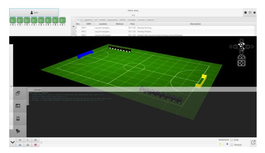
3D representation of the field The GUI has a 3D component to represent the field. Since other teams in SSL soccer are starting to master the use of the chipper, we are trying to anticipate this by using a 3D representation of the field which can visually represent the vertical position of the ball. The 3D environment has controls for several pre-set views of the field and a camera which can be set at any angle and moved to any position of the field. We make use of our own layer built on top of JavaFX which binds all data in the model to the 3D environment. This gives us instantaneous support for arbitrary field sizes, multiple goals, multiple balls, non-standard team-sizes, and other Technical Challenge material.
Game log player In order to review game logs and support replay of game data we have built a game log player into the system. The application allows engineers working on the strategy to test certain moves which have been logged before during matches and tests and review their usability. We are currently in the process of integrating the game log player with the robot control unit in order to play back game logs with physical robots.
4.2 Strategy
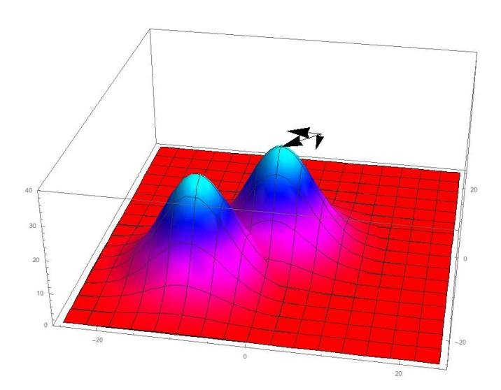
The strategy system received a complete overhaul. We decided to use a simple energy-based model [4] in which the information gathered about a robot, such as position, velocity, and orientation, is mapped to scalar quantities in a two-dimensional grid. This way we can visually represent the state of the game in a sort of heatmap (see Figure 6) and translate strategic problems, such as determining the optimal destination for a robot or determining success rate of a shot, into problems of vector calculus, such as finding local minima/maxima, or performing a line integral. The model we have developed so far draws on both energy-based models [4] and ideas from anti-gravity movement [5]. As our research in this area appears to be novel, we are in the progress of writing an additional paper on this topic and would welcome any questions and/or suggestions.
4.3 Pipelines
To manage the incoming stream of data from ssl-vision and ssl-referee and the outgoing streams of data to the robots we have built our own asynchronous stream processing framework. The framework is multithreaded and processes packets on a first-come first-served basis. Packets of data are classified and processed by the corresponding data pipeline. An I/O management system is used to read network packets and transform protobuf data to a packet suitable for the pipeline before processing.
The architecture of a data pipeline in this system consists of producers, couplers, and consumers. Producers generate data and are primarily used in the absence of real ssl-vision data to simulate games. Couplers are used to transform data and are used in computing data corrections and transformations, such as the unscented Kalman filter we use, calculation of strategy-related metrics, or eg. a ghosting filter. Lastly, consumers catch packets at the end of a pipeline and are used to update a model, the console, or a file.
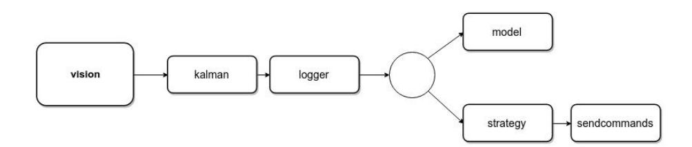
Managing dataflow To be able to express the flow of data in a human-readable format we created a regular language to denote pipeline-routes. This language, named PEPE (short for PEPE: Evaluates Pipeline Expressions), can handle parallel and series processing of data and has support for functions. A PEPE expression could look like the following:
vision > kalman > logger > (model | (strategy > sendcommands))
which would result in the pipeline route being created as shown in Figure 7. The main motivation in using such a language is to make it easier for nonsoftware engineers to quickly build and/or modify testing environments without learning the application's internal working.
4.4 LUA
Besides having a language to express the flow of data, we wanted to have scripts which could be used to alter the flow of data based on the state space configuration. In choosing a language for these scripts we decided to go for a well-known high-level language: Lua. Lua has been used by at least one other team in the league [3] and considering its simplicity and easy-to-read syntax we believe the use of a high-level language for expressing global strategies will enable more people to work on such strategies.
A console was added to the GUI which functions as a Lua REPL (Read-Eval-Print-Loop). Also, an editor with syntax highlighting was created to write, save, and execute Lua scripts. Internally, we expose Java objects to the Lua engine by adding an annotation (@AvailableInLua) to the class.
References
- Emmerink, T., Berg, R. van den, Overeem, J.W., Hakkers, T., Jong, J. de, Van Ommeren, J., Meulenkamp, R.: SSH Team Description Paper for RoboCup 2015. Enschede (2015)
- Williams II, R.L., Carter, B.E., Gallina, P., Rosati, G.: Dynamic Model with Slip for Wheeled Omni-Directional Robots. Final Manuscript, IEEE TRANSACTIONS ON ROBOTICS AND AUTOMATION, (2002)
- Zhao, Y., Xiong, R., Tong, H., Li, C., Fang, L.: ZJUNlict Team Description Paper for RoboCup 2014. Zhejiang (2014)
- LeCun, Y., Chopra, S., Hadsell, R., Ranzato, M., & Huang, F. (2006). A tutorial on energy-based learning. Predicting structured data.
- Anti-Gravity Movement. (n.d.). Retrieved December 5, 2015, from http://robowiki.net/wiki/Anti-Gravity Movement