Extended Team Description for RoboCup 2016
Andre Ryll, Mark Geiger, Nicolai Ommer, Arne Sachtler, Lukas Magel
Department of Information Technology, Department of Mechanical Engineering Baden-Wuerttemberg Cooperative State University, Coblitzallee 1-9, 68163 Mannheim, Germany
https://www.tigers-mannheim.de
Abstract This paper presents a brief overview of the main systems of TIGERs Mannheim, a Small Size League (SSL) team intending to participate in RoboCup 2016 in Leipzig, Germany. This years' EDTP focuses primarily on the wireless communication protocol of our robots. The nRF24L01+ module is widely used in the SSL. To lower the burden for new teams and eventually improve the performance of existing teams radio quality the wireless protocol of TIGERs Mannheim is explained in depth.
1 Mechanical and Electrical System
This year, we have decided to make the second major redesign of our robots since our rst participation in 2011. The most important changes are the substitution of 30W motors by 50W variants and larger main wheels with more rollers. The new wheels also use X-Ring rubbers on their rollers. We also increased the number of rollers on each wheel to 20 (from 15 in the previous version). This leads to a much smoother movement with more traction. Furthermore, the wheel's diameter has been increased to yield a higher top speed. Figure 1 shows in image of our rst assembled prototype.
The dribbling motor has been exchanged as well. The Maxon EC-16 was found to be too fragile and too expensive. It has been replaced by the Maxon EC-max 22. Although it has 5W less power, its performance is comparable to the previous motor.
The main electronics board has been completely redesigned as well. The previous version with 5 microcontrollers was found to be too complex. All microcontrollers were replaced by an STM32F7 which is a Cortex-M7 microcontroller clocked at 216MHz. This single microcontroller can run the complete sensor fusion and robot control on one CPU. Motor controller microcontrollers have been replaced by the Allegro Microsystems A3931 3-Phase BLDC controller IC [1].
Table 1 outlines the technical details of the 2013/2014 version and the new 2016 version of our robots. Depending on the available budget, we will either participate with the old robots, the new ones, or a mixed team of both.
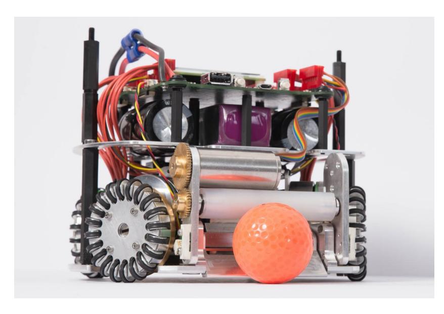
Table 1. Robot Specifications
| Robot version | 2013/2014 | 2016 |
|---|---|---|
| Dimension | Ø178 x 148mm | Ø179 x 146mm |
| Total weight | 2.9kg | 2.5kg |
| Max. ball coverage | 12.3% | 19.7% |
| Driving motors | Maxon EC-45 at 30W, Maxon EC-45 at 50W | |
| Gear | 15 : 50, 18 : 60 | |
| Gear type | ||
| Wheel diameter | 51mm | 57mm |
| Encoder | US Digital E8P, 2048 PPR [2] | |
| Dribbling motor | Maxon EC-16 30W with planetary gear head (1 : 4.4) | Maxon EC-max 22, 25W |
| Dribbling gear | 48 : 24 | 50 : 30 |
| Dribbling bar diameter | 12mm | 17mm |
| Kicker charge topology | SEPIC | |
| Chip kick distance | approx. 4m | |
| Straight kick speed | max. 8m/s | |
| Processors | 2x STM32F407 [3], 3x STM32F303 [4] | STM32F746 [5] |
| Used sensors | Encoders, Gyroscope, Accelerometer | Gyroscope, Optical Flow, Accelerometer |
| Communication link nRF24L01+ @2MBit/s, 2.400 - 2.525GHz [6] |
2 Wireless Communication
Wireless communication is an essential part of most team-based RoboCup disciplines. Compared to other leagues, the SSL is very fast paced and the robots are centrally controlled. This imposes special requirements on the wireless communication to each robot. It has to be fast and deterministic.
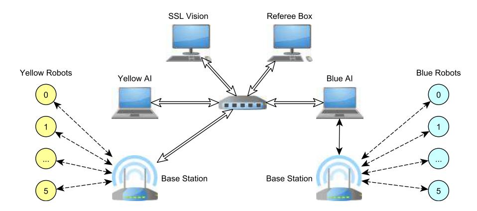
Figure 2 shows an overview of a typical SSL network layout. The blue team uses the conventional appoach of a central AI computer connected to the ocial network (with vision and referee) and to a base station for communicating with their robots. This direct connection between the AI computer and the base station has the advantage of low latency and guaranteed bandwidth.
The yellow team uses our approach of a network-capable base station. This may look as a disadvantage at rst because there is one additional hop from AI computer to base station and the bandwidth can be inuenced by other network participants. As the network is usually a gigabit switched ethernet, both disadvantages only exist theoretically. The used bandwidth of all participants is in the range of 10MBit/s. Collisions cannot occur due to the switched nature of ethernet and the latency from any participant to any other is below 1ms. The network-capable base station has three major advantages. First of all, a network connection is well supported on every operating system and programming language. Experience showed, that e.g. a serial connection in Java can be challenging. This problem is mitigated with a network connection. Such a connection is also well supported by modern microcontrollers. A second advantage is the possibility to directly receive the robots' position from the SSL Vision on the base station and forward it to each bot. This lowers the latency from position capture to the arrival of the position on the robots as this information is not passed through an additional computer (e.g. the blue AI's computer). We extensively use this feature for our sensor fusion which is running on each robot individually. The last benet is the implementation of the shared radio protocol directly on the base station. Thereby, another team can use our robots without needing our AI computer or software.
The following sections will describe our base station in detail to allow other teams to benet from our experience. The exact schematics of the base station and also the full source code can be found in our previous open-source release[1].
2.1 Base Station Hardware
The hardware of the base station is outlined in gure 3. The main element is an STM32F4 microcontroller from STmicroelectronics [3]. This Cortex-M4 microcontroller is clocked at 168MHz and features special periphery for interfacing ethernet networks and SPI devices (like the nRF24L01+ chip). The ethernet interface requires an additional PHY chip, which implements the physical layer and manages bit encoding/decoding for ethernet data. The DP83848[7] is frequently used together with the STM32 and several examples exist for this combination. Data is transferred from the PHY chip to the STM32 by automated DMA transfers. This lowers CPU load and improves transfer performance. The STM32 is also able to automatically insert Ethernet, IP, and UDP checksums.
Apart from the network interface, the base station has two slots for 8-pin nRF24L01+ modules. Each module is connected via a dedicated SPI bus to the STM32. The dedicated bus is important to meet the timing specications outlined in section 2.3 and to reduce noise on the chip which can lead to a bad link quality. Up to now, we only use one module in the base station. The option for a second module can be used to either implement redundancy or to control another team of robots on a dierent frequency. Thereby a full match with two teams can be radio-controlled by a single base station.
We selected the nRF24L01+ single chip transceiver for our wireless communication. It is very common in the SSL and well suited for the previously mentioned requirements. Its main characteristics with our implementation are outlined in table 2. The base station uses a module with power amplier and external antenna. The robots use small modules with a PCB antenna.
The hardware is nalized by a JTAG connection to program the STM32 and a USB-Serial interface used for a console and debugging. Additionally, the whole base station is powered via this USB interface.
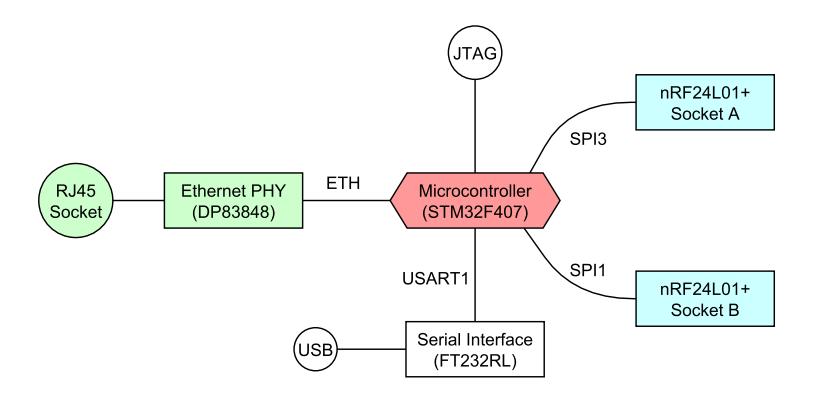
Table 2. nRF24L01+ key characteristics
| nRF24L01+ | |
|---|---|
| Frequency | 2.400 - 2.525GHz |
| Bandwidth | 2MHz (1MHz @1MBit/s or 250kBit/s) |
| Speed | 2MBit/s, 1MBit/s, 250kBit/s |
| Access Pattern | TDMA |
| Latency | Fixed |
| Non-Overlapping Channels | 62 @ 2MBit/s, 125 otherwise |
2.2 Base Station Software
The software running on the STM32 uses the chibiOS[2] free operating system. It allows to create multiple tasks and lets them run based on readiness and priority. The two most important tasks are the Network task (low prio) and the Wi Task (high prio). The Network task runs event-based. It gets notied whenever there is a packet ready on the ethernet interface or on one of the robot wireless queues. Figure 4 shows an overview of the dataow in the base station and also shows the main buering memories/queues. The Wi Task runs strictly interval based and processes one robot on each interval.
Network Task Data from the network, which is addressed (either unicast or multicast) to the base station is transferred automatically via DMA to the ETH RX buer. It is organized as a ring-buer with 64 slots of 128 byte each. If a packet is larger than 128 bytes it is automatically split and distributed among succeeding slots. In the SSL environment, a high number of small packets is very common. Consquently, the ring-buer consists of short 128 byte slots.
Whenever a slot is lled, the Network task is notied. If a complete packet arrived and passed all checksum tests (done automatically in hardware) it is polled from the Network task and put in the RX processing buer. It has a size of 1524 byte which is the maximum size of a regular ethernet frame.
We implemented a custom UDP/IP stack on the base station. Freely available stacks were either too complex, missed features (e.g. IGMP) or were simply too slow. Our own implementation uses zero-copy during decoding, which makes this implementation very fast. We implemented the following protocols:
- Ethernet
- ARP (required to map MAC addresses to IPs)
- ICMP (responds to the well-known ping command)
- IP
- UDP
- IGMPv3 (required to join multicast groups, e.g. from the SSL Vision)
This network stack is able to achieve a throughput of up to 45MBit/s. This is far beyond the requirements of the SSL environment. If the packet is an ARP, ICMP or IGMP packet it is handled accordingly and a response packet is eventually sent out again.
If the packet is from the SSL Vision it is decoded and all robot positions are stored internally. These positions are later on used by some robot commands to forward this position to the robots. The decoding of the protobuf messages is done with the protobuf-c library[3]. This library automatically generates C code from the protobuf message denitions to decode and encode such messages. It furthermore allows to employ custom allocators for environments where dynamic memory allocation is not possible. This is also used on the base station, as memory managament there is fully static.
If the packet is on the shared radio port it is handled accordingly and sent to another internal task. The RST task processes it and generates the according robot commands.
If the packet is a robot command from our central AI, it is encoded again and put into the according wireless queue on the base station. The base station itself does not know the content of the command. The content is packed in an abstract byte eld. This allows to add new commands to the AI and the robots without the need to modify the base station's code. Nevertheless, there is one exception to this approach. Some commands from the AI include unset elds which are lled up by the base station with the current position of the robot. These commands must be known and recognized by the base station.
Whenever a packet is completely received on one of the wireless queues the Network task is notied as well. It then fetches the data from the queue and creates a UDP/IP packet addressed to our central AI. The TX buer (1524 byte) is used to store data as well as UDP, IP, and Ethernet headers during package assembly. This buer is protected by a mutex to avoid resource conicts if another task wants to send Network data as well.
Wi Task For each possible robot the base station has one wireless TX (400 byte) and one RX queue (200 byte). This makes a total of 24 TX/RX queues for 12 yellow and 12 blue robots. In theory the base station can therefore handle 24 robots simultaneously. The wi task works with xed time slots. The duration of these slots is dictated by the nRF24L01+ speed setting. Table 3 summarizes the settings and the corresponding update rates for one and eight robots.
During each time slot up to 32 bytes can be transferred to one robot and 32 bytes of acknowledgement payload data can be retrieved from one robot. The Wi task subsequently goes through all 24 robot queues. Robots that are indicated as oine are skipped. E.g. if only one robot is online, this results in an update rate of 1kHz for that robot. The processing of all robots once is subsequently called a run. To detect if a new robot came online two methods can be used.
The rst method uses one slot after all online bots have been processed to query a robot which is listed as oine. If it responds, it is marked as online. This results in a dynamic total runtime for a complete run through all online robots as the runtime depends on the number of available robots.
A xed runtime is sometimes preferable to state an upper limit on the total runtime and consequently the maximum latency that can occur. This is done with the second detection method. The number of robots to process during each run is xed. Here, the online robots are processed rst as well. Afterwards, the remaining slots in that run are used to check for new robots. E.g. if the number of robots to process is xed to 8 and 3 robots are currently online, then 5 slots will afterwards be used to check for new robots. This also reduces the time until a new robot is discovered.
During processing one time slot the CPU is not completely occupied. It retrieves data from the TX queue and forwards it to the nRF24L01+ chip. Afterwards it sleeps until the slot time elapsed and retrieves the data from the nRF24L01+ chip and puts it in the RX queue. During the idle time, the Network task or other lower priority tasks can execute.
This access scheme eectively generates a centralized Time-Division Multiple-Access (TDMA) pattern on the base station. In summary, this avoids collisions on-air and provides an eective bi-directional transfer channel with the use of only a single frequency.
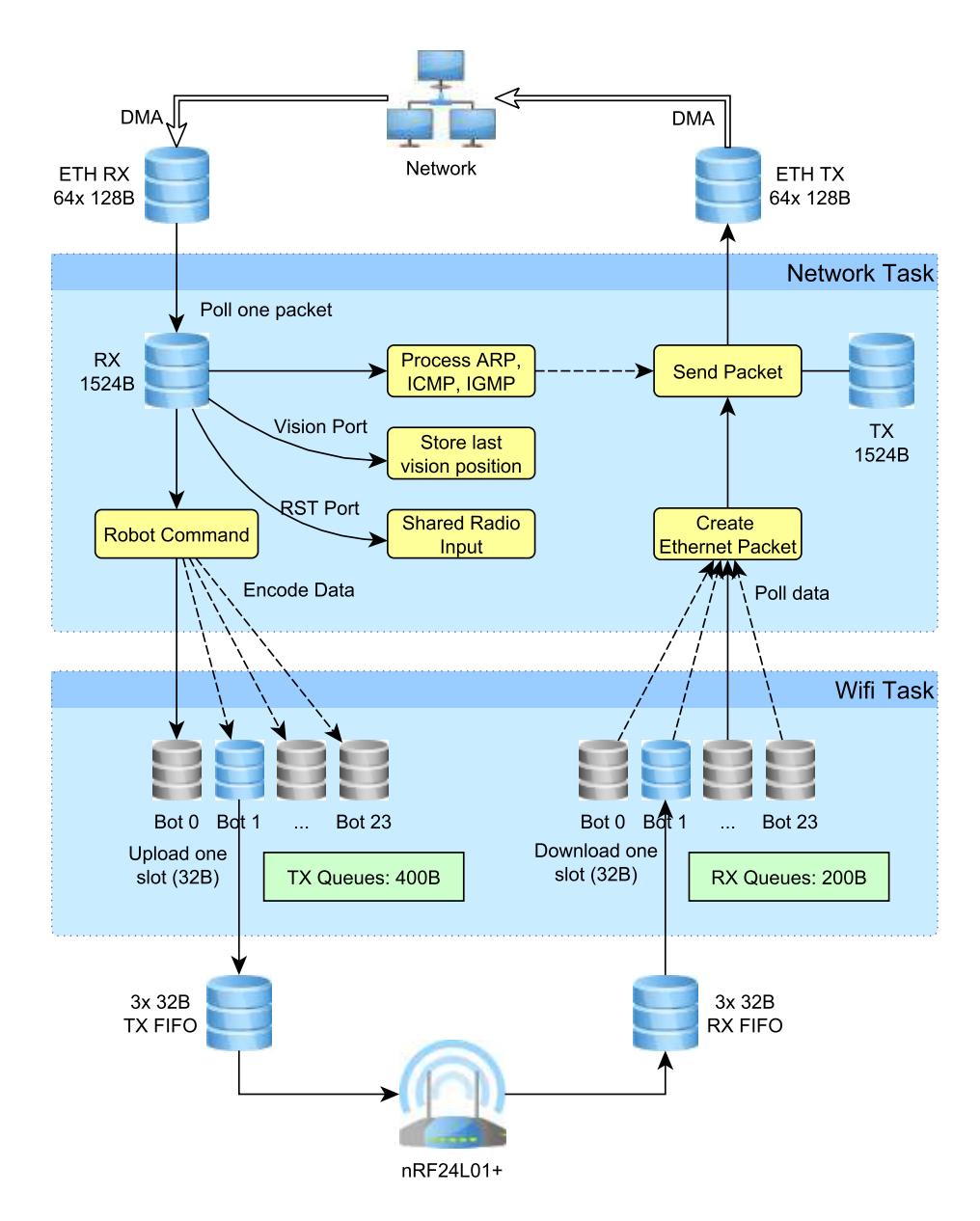
Table 3. Wi Task slot times and update rates depending on link speed
| Speed | Slot Duration Update Rate (1 Bot) Update Rate (8 Bots) | ||
|---|---|---|---|
| 2MBit/s | 1.0ms | 1000Hz | 125Hz |
| 1MBit/s | 1.2ms | 833Hz | 104Hz |
| 250kBit/s | 3.5ms | 286Hz | 36Hz |
2.3 Interfacing the nRF24L01+
To interface the nRF24L01+ chip, one SPI bus, one enable data line (chip enable), and one external interrupt line is required. Furthermore, a timer with microsecond precision is needed for optimal performance. The SPI bus is clocked at 656kHz. The external interrupt is handled by the STM32's EXTI periphery block which can generate a software interrupt and execute code with minimal delay.
We use some of the features of the Enhanced ShockBurst data link layer of the nRF24L01+ to achieve best performance in the SSL environment. We explicitly use the following features:
- 1-32 byte dynamic payload length
- Automatic packet handling
- Auto acknowledgement with payload
Although it might look promising we do NOT use the following features:
- Auto retransmit
- 6 data pipe MultiCeiver for 1:6 star networks
Auto retransmit leads to a non-deterministic transmission time, depending on the number of retransmits. This is not desirable in an environment where we want to achieve minimum latency. With the MultiCeiver feature one nRF24L01+ congured in receive mode can receive data from up to 6 transmitters. We do not use this feature because our base station only operates as transmitter (data from robots is contained in the ACK payload) and because this feature is limited to 6 robots. As soon as there are more robots per team, this approach is not extendable any more.
Table 4 shows the conguration of the nRF24L01+ chip for our purpose. The most important settings are the use of a 2 byte CRC and a 3 byte address eld. Furthermore, the Enhanced ShockBurst settings outlined above are activated. We only use the data pipe 0. Although retransmissions are disabled, the retransmit delay needs to be adjusted as well. It also determines the timeout for packets with acknowledgement payload.
Listing 1 shows the pseudo-code for processing one robot slot on the base station (refer 2.2). At a rate of 2MBit/s the precision timer is started with a timeout of 1ms (see table 3).
Algorithm 1 Pseudo-Code for handling one robot slot. Settings are 2MBit/s. Robot address is 0xF1F1F1.
s t a r tTim e r ( p r e ci si o nTim e r , 1ms)
w ri teReg (RX_ADDR_P0, 0xF1F1F1 )
w ri teReg (TX_ADDR, 0xF1F1F1 )
w ri teReg (W_TX_PAYLOAD, TXPayload [ ] )
ChipEnable ( )
waitFor (nRF_IRQ) // data t r a n smi t t e d
ChipDi s able ( )
s t a t u s = readReg (STATUS)
rxLen = readReg (RX_PW_P0) // RX payload width
i f s t a t u s == RXDataReady
          i f rxLen > 32
                    writeCmd (FLUSH_RX)
          e l s e i f rxLen > 0
                    rxPayload [ ] = readReg (R_RX_PAYLOAD)
          end
end
i f s t a t u s == MaxRT // means no acknowlegdement
          writeCmd (FLUSH_TX)
end
w ri teReg (STATUS, 0 x70 ) // c l e a r a l l s t a t u s f l a g s
waitFor ( p r e ci si o n Tim e r )
First of all, the address for RX and TX is congured. Each of the 24 possible robot IDs (12 yellow + 12 blue) has its own address. There exists a look-uptable for each ID to translate it to an address. Although the ID could directly be used as address, this is not advisable. According to the nRF24L01+ datasheet, the address should not toggle only once (only one change from 0 to 1 in the bitstream) or be a continuation of the preamble used in each wireless packet (0xAA or 0x55).
Afterwards, up to 32 bytes of payload data to transmit are uploaded to the nRF24L01+. The chip is then enabled to start the wireless transfer. The completion is signalled by an external IRQ. After the reception of this IRQ, the chip is disabled.
To determine if the transmission was successful, the status and the RX payload width is read. If the RX data ready ag is set, this means the robot attached payload data to its acknowledgement. If the length is larger than 32 byte an error occured during transmission and the RX queue on the nRF24L01+ needs to be ushed. If the length is smaller, the RX data will be read from the chip. If there was no acknowledgement, this is signalled by the maximum retransmission ag. This also works if zero retransmissions are congured. In that case the TX queue should be ushed.
Finally, after data has been transmitted and received the status ags are cleared with a write to the STATUS register. The complete process should nish before the precision timer expires. Hence, the STM32 now waits for this timer to expire to maintain its xed TDMA schedule.
Listing 2 briey shows the processing on the robot side. The robot always runs its nRF24L01+ module in receive mode. It always waits for an interrupt which signals the module received data. Empirical tests have shown that the received data cannot be read immediately. At a data rate of 2MBit/s a delay of 300us is required before the data can safely be read. At 1MBit/s 500us are required and at 250kBit/s 1500us are needed.
Algorithm 2 Pseudo-Code showing nRF24L01+ processing on one robot.
w hil e ( 1 )
            waitFor (nRF_IRQ)
             d el a y ( 3 0 0 us )
             r e a dAllP a c k e t s ( )
             s t a r tTim e r ( p r e ci si o n Tim e r , 300 us )
             p r o c e s sR e c ei v e dP a c k e t s ( )
            waitFor ( p r e ci si o n Tim e r )
            uploadAckPayload ( )
end
The nRF24L01+ chip has two internal FIFOs with 3x 32 byte each (one for RX and one for TX). After the delay has expired data is read from the chip until the RX FIFO is completely drained. Then the precision timer is started again with a timeout of 300us. During this time the received packets are processed. After the timer expired the TX FIFO of the module is lled with data to be attached to the acknowledgement when the robot is addressed the next time.
The second delay ensures that data is transferred to the module before it is queried the next time. In total the delay is 600us from the time of the IRQ of the last transfer. This leaves 400us as a buer in case the operating system jitter and higher priority tasks delay the upload. It is crucial to upload the data before the module is active again. Otherwise, the data is lost.
Table 4. nRF24L01+ register settings which dier from default
| Address | Mnemonic | Value | Description |
|---|---|---|---|
| 0x00 | CONFIG | 0x0E | transmitter, power up, CRC16, no IRQs masked |
| 0x02 | EN_RXADDR | 0x01 | Only enable data pipe 0 |
| 0x03 | SETUP_AW | 0x01 | 3 byte address eld |
| SETUP_RETR 0x10 | @1MBit/s or 2MBit/s: retransmit delay 500us | ||
| 0x04 | 0x50 | @250kBit/s: retransmit delay 1500us | |
| 0x05 | RF_CH | - | Depends on selected frequency |
| RF_SETUP | 0x0E | 2MBit/s, +0dBm output power | |
| 0x06 | 0x06 | 1MBit/s, +0dBm output power | |
| 0x26 | 250kBit/s, +0dBm output power | ||
| 0x0A | RX_ADDR_P0 | - | Depends on addressed robot |
| 0x10 | TX_ADDR | - | Depends on addressed robot |
| 0x1C | DYNPD | 0x01 | Dynamic payload length on pipe 0 |
| 0x1D | FEATURE | 0x07 Enable dynamic payload length and ACK payload |
2.4 Wireless Protocol
On the lowest level our wireless protocol is based on the nRF24L01+ chip which allows to transfer data chunks of up to 32 byte. We can make two assumptions about this communication channel:
- Packets always arrive in the order they were sent (in-order), no re-ordering or retransmission occurs
- Packets arrive completely and correctly or not at all. This is ensured by the 2 byte CRC of the Enhanced ShockBurst data link protocol.
Upon these assumptions we built our transport layer. The rst byte of the available 32 bytes is always used as control byte. This leaves 31 bytes for data. The control byte is further divided into one data continuation bit (DCB) and 7 bits for a sequence number. The sequence number is incremented with every transmitted packet. This allows the receiving side to determine if a packet has been lost. Statistically this is also used as a link quality indicator.
Even if the base station does not have any command to send to the robots the control byte is always sent. It is essential to use a sequence number here, otherwise data can be wrongly detected as duplicate by the nRF24L01+ module.
Explanation: The module uses the 2 byte CRC and a 2 bit PID eld to identify duplicate packets. The PID is incremented after each transmission. If the PID and CRC are equal, the packet is duplicate. If a sequence number is not used, the payload and consequently the CRC is always the same. If we have a multiple of 4 robots online, each robot will always receive a packet with the same PID (with two bits only 0-3 are possible values). As the PID and the CRC are now identical, the data is identied as duplicate and dropped. A lost link is detected although the module still receives correct data.
To use the transfer channel with 31 byte blocks as eectively as possible, it is desirable to combine multiple small commands into one packet. This also requires to determine the end of one packet and the start of a new packet. Furthermore, commands that are larger than 31 bytes need to be split into multiple packets.
In our wireless protocol, we use the zero (0x00) as packet delimiter. It is appended after each command. This requires that all zeros which exist in the command data need to be removed. We achieve this by the use of a technique called Consistent Overhead Byte Stung (COBS) [8]. The original implementation of this technique has a maximum of 1 byte overhead for every 254 byte of data. It eectively encodes all zeros in the command datastream. We also employ two extensions to this technique which are called Zero Pair Elimination (ZPE) and Zero Run Eliminiation (ZRE). This reduces the encoding ratio to 1 byte overhead for every 208 byte of data. It has the benet of compressing 2-15 succeeding zeros into a single code byte. Such zeros occur very often in command data. E.g. a small 32bit integer value often has 2 or 3 leading zeros if the byte stream is considered.
Any command to a robot is COBS encoded and a zero is appended. This encoded data is then put into the robot's Wi TX queue (see g. 4). Commands from this queue are used to ll a 31 byte temporary buer. Depending on the encoded command size, this can be one or more commands. As soon as 31 bytes are reached or there are no more commands, the data is transferred to the nRF24L01+ TX FIFO, prepended by the control byte. If a command crosses the 31 byte boundary it is considered a split packet. In this case, the rst chunk of this command is sent in time slot tn and the second chunk in time slot tn+1. If the command is larger, it can even span multiple packets. Whenever a command is continued in one packet, the DCB is set.
The use of the packet delimiter code character and the DCB makes this protocol very robust in terms of packet loss. A packet loss is identied by a jump greater than one in the sequence number. If the DCB is not set, this means that a new command starts at byte 2 of the received data (rst byte is the control byte). It does not matter if any loss occured before. If the DCB is set and a loss is detected this means that a command is continued from byte 2 on. This data is useless as the previous packet has been lost. In this case, the new data is scanned for a packet delimiter. If one is found, retrieval of a new command restarts from there. Without the DCB it would not be possible to determine if data starting at byte 2 is valid or needs to be discarded. Only looking for the packet delimiter then eventually leads to discarding data that is actually complete.
The transport layer of our wireless protocol is quite generic. It makes no assumptions about the data to be transmitted nor about its size. It can compress, transmit, and encode any number of bytes. With COBS and a single byte packet delimiter it makes most eective use of the available transport channel.
2.5 Robot Control Data
On top of our wireless protocol we implement the actual commands to be sent to and received from our robots. Each command is prepended by a header structure. The standard header structure consists of 2 bytes. One byte identies the command ID and one byte the section ID. This is a logical separation to allow a faster distribution of the commands. If the most signicant bit of the command ID is set, this packet uses an extended header. The extended header appends a 2 byte sequence number to the standard header. This sequence number is used for retransmissions.
Reliable Transport Layer Neither the nRF24L01+ data link layer nor our wireless protocol implements any retransmissions. A reliable transport layer thus needs to be build on top of the wireless protocol. We implement a simple acknowledgement with sequence numbers and xed timeouts for retransmitting lost packets. Each command can individually be agged as reliable by setting the most signicant bit (MSB) in the command ID eld.
If the robot receives a reliable command from the AI, it responds with an acknowledgement command (ACK) which contains the sequence number of the received command. The acknowledgement itself is not sent reliable.
If the robot wants to send a reliable command, it is rst enqueued in a reliable command queue. Only one unacknowledged reliable packet can be in ight at any time. This avoids problems with ACKs received out-of-order and packets that would need to be removed from the sent queue out-of-order as well. This is not possible with our FIFO structured queue. As soon as the reliable queue contains a command and no other reliable command is being processed the command is sent as usual. If an acknowledgement is received within 100ms the command is removed from the queue and the next reliable command is sent. If no ACK is received, the command is retransmitted.
Due to eventual retransmissions and the additional queue, a worst case transport delay cannot be stated. It should therefore not be used for time-critical data. We primarily use reliable commands for conguration options and parameters. During a match, no reliable commands are used.
Match Commands and Feedback During a match only two commands are used. The match control command shown in table 5 is sent from our AI to the robots. The match feedback command shown in table 6 is sent from each robot back to the AI.
The match control command has 27 bytes in total. The packet header adds 2 more bytes. With COBS encoding one additional byte needs to be added in the worst case. Finally, the packet delimiter adds another byte. This leads to a total size of 31 bytes. This ts perfectly into the wireless protocol transport layer and ensures that the command always ts in one packet as long as no other data is transmitted.
The rst two elds in the match control command can either be lled by our AI, or by the base station. The base station automatically inserts the last position received from the SSL Vision if this eld has not been set by the AI. The position delay is also lled out by the base station to let the robot know how old the position information is. This is useful to interpolate the data on the robot to the current time (based on the sensor fusion). The next three elds are used to control the kicker and dribbler of our robot. The ags are used for special situations, e.g. a stop situation where the robots are only allowed to move at a limited speed. The feedback frequency indicates the rate at which match feedback commands shall be sent.
The skill ID eld indicates how the last 12 bytes of data shall be interpreted. We noted that robot control data can change quite often during development. This primarily concerns the movement. Some basic skills are e.g. a position command which needs 6 bytes (XY position + orientation) or a local velocity command. More advanced commands can even use a position and velocity and occupy the full 12 bytes. This system also allows to implement local skills on the robot. E.g. a penalty shooter can be implemented completely on the robot. The skill data would contain the opponent's goalie position and the ball position. Unused bytes in the skill data are not transmitted. Consequently, the match command is often shorter than 31 bytes.
The match feedback command (table 6) is completly fixed and sent at a rate determined by the match control command. The first two fields contain the current position and velocity of the robot. These values are calculated by our onboard sensor fusion. This data is very accurate due to the additional local sensors (gyro, accelerometer, encoders) and allows to sent precise position information to the AI even if the robot is currently not visible on the SSL Vision.
The next two values contain the current kicker capacitor voltage (up to 190V) and the current dribbler speed. The battery level indicates the remaining voltage on the main battery. The barrier & kick counter value is a bit field. The MSB indicates if the infra-red barrier in front of the robot is interrupted. The remaining 7 bits contain a kick counter. Whenever a kick is executed, this value is incremented. This allows the AI to determine if a kick actually occured.
The features field is a bit field as well. There is one bit for movement, straight kick, chip kick, dribbler, and infra-red barrier. If the corresponding bit is set this means that the subsystem is working properly. If the robot detects a damage to a subsystem, the corresponding bit is cleared. The AI may then use this information to dynamically reassign the robots' role. E.g. a robot with a damaged chip kicker should not be used for a throw-in.
The hardware ID is a unique identifier of each robot independent of its vision ID. This is used to generate robot specific statistics. The dribbler temperature is indicated by the last field. In close-contact situations the dribbling motor can heat up very quickly. To prevent damage to the motor, the temperature is reported to the AI.
Table 5. Match Control command structure. Total size: 27B
| Offset | Size | Type | Name | Unit |
|---|---|---|---|---|
| 0 | 6 | int16_t curPosition[3] | mm | |
| 6 | 1 | uint8_t | posDelay | Q6.2 ms |
| 7 | 2 | uint16_t kickDuration | us | |
| 9 | 1 | uint8_t | kickFlags | mode, device |
| 10 | 2 | uint16_t dribblerSpeed | RPM | |
| 12 | 1 | uint8_t | skillId | - |
| 13 | 1 | uint8_t | ags | limitedVelocity |
| 14 | 1 | uint8_t | feedbackFreq | Hz |
| 15 | 12 | uint8_t | skillData | - |
Table 6. Match Feedback command structure. Total size: 22B
| Offset | Size | Type | Name | Unit |
|---|---|---|---|---|
| 0 | 6 | int16_t | curPosition[3] | mm |
| 6 | 6 | int 16_t | curVelocity[3] | mm/s |
| 12 | 1 | uint8_t | kickerLevel | V |
| 13 | 2 | uint16_t | dribblerSpeed | RPM |
| 15 | 2 | uint16_t | batteryLevel | mV |
| 17 | 1 | uint8_t | brrierKickCount er | - |
| 18 | 2 | uint16_t | features | bit-field |
| 20 | 1 | uint8_t | hardwareId | - |
| 21 | 1 | uint8_t | dribblerTemp | K/2 |
3 Publication
Our team publishes all their resources, including software, electronics/schematics and mechanical drawings, after each RoboCup. They can be found on our website[4]. The website also contains several publications[5] about the RoboCup, though some are only available in German.
References
- LLC Allegro MicroSystems. Automotive 3-Phase BLDC Controller and MOS-FET Driver, 2013. http://www.allegromicro.com/~/media/Files/Datasheets/ A3930-1-Datasheet.ashx?la=en.
- US Digital. E8P OEM Miniature Optical Kit Encoder, 2012. http://www.usdigital.com/products/e8p.
- STmicroelectronics. STM32F405xx, STM32F407xx Datasheet, 2012. http://www.st.com/web/catalog/mmc/FM141/SC1169/SS1577/LN1035/PF252144.
- STmicroelectronics. STM32F302xx, STM32F303xx Datasheet, June 2013. http://www.st.com/web/catalog/mmc/FM141/SC1169/SS1576/LN1531/PF253449.
- STmicroelectronics. STM32F745xx, STM32F746xx Datasheet, December 2015. http://www.st.com/st-web-ui/static/active/en/resource/technical/document/datasheet/DM00166116.pdf.
- Nordic Semiconductor. nRF24L01+ Product Specification v1.0, 2008. http://www.nordicsemi.com/eng/Products/2.4GHz-RF/nRF24L01P.
- Texas Instruments. DP83848C/I/VYB/YB PHYTER QFP Single Port 10/100Mb/s Ethernet Physical Layer Transceiver, May 2007. http://www.ti.com/lit/gpn/dp83848c.
- S. Cheshire and M. Baker. Consistent overhead byte stuffing. Networking IEEE/ACM Transactions on, 7(2):159–172, Apr 1999.