2016 Team Description Paper: UBC Thunderbots
Ryan De Iaco, Stephen Johnson, Fakherdin Kalla, Lynx Kevin Lu, Mathew MacDougall, Kawindi Muthukuda, James Petrie, Michaela Ragoonath, Wei Yi Su, Vincent Tang, Tiffany Tsu, Brian Wang, Graham Whyte, Cheng Xi, Komancy Yu, Eric Zhang, Kevin Zhang
The University of British Columbia, Vancouver, BC, Canada
Abstract This paper details the design improvements UBC Thunderbots has made in preparation for RoboCup 2016 in Leipzig, Germany. The primary focus was to build on the existing artificial intelligence of the robot by implementing coroutines into high-level software while refining current features. The secondary focus involved optimizing electrical, firmware and mechanical systems.
1 Introduction
UBC Thunderbots is an interdisciplinary team of undergraduate students at the University of British Columbia. Established in 2006, it pursued its first competitive initiative within the Small Size League at RoboCup 2009. The team has consecutively competed in RoboCup from 2010 to 2015 and is currently seeking qualification for RoboCup 2016. Over the years, it has made significant developments of its team of autonomous soccer playing robots. This paper will outline the progress in implementation of the current model of robots, focusing on the mechanical, electrical and software components with particular emphasis on the artificial intelligence (AI) plays.
2 Mechanical Design
2.1 Drivetrain
Motor Mount: The overall design of the motor mounts is the same as the 2015 revision, with a few minor changes. The material has been changed back to aluminium, as stainless steel cannot be easily machined during competition. Helix coils were added to the threads connecting the motor mounts to the baseplate (M3), and the motor mounts to the wheel (M5). This was done to increase the robustness of the aluminium threads over time. Rubber padding was also added between the baseplate and motor mounts—this was done to compensate for the wheel height differences across the four wheels of the robot. The rubber padding acts as a "suspension" system by giving the motor mounts a little room for adjustment.
2.2 Chipper
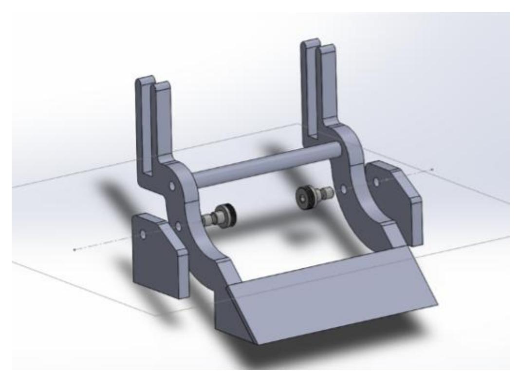
With the aim of increasing mechanical compactness, we devised a chipper assembly that allows for a horizontal chipper plunger motion while still maintaining the optimal angle of ball contact at 45 degrees. As Figure 1 illustrates, the planned chipper mechanics compose of a flat solenoid-pulled plate with mostly water-jetted steel pieces. The retraction force comes from torsion springs to be mounted on the pivot bolts. The new layout is estimated to reduce the height of the chipper assembly by about 1.5cm, allowing for more space for potential electrical expansion in the future.
2.3 Kicker
The kicker is mostly unchanged with the exception of the plunger stopper redesign. The two-screw stopper design operated successfully for a period of time before the deformation loosen the screw and required replacement. The new design has extended the plunger stopper on the left and right, resulting in a better surface impact. Additionally, a new stopper block has been installed on the base plate to absorb the impact and stop the plunger from clashing the spring and destroying the kicker solenoid housing.
2.4 Dribbler
Frame: The current design has a frame that holds the dribbler, motor, and gearing. It slides on two diagonal baseplate mounts and is restrained by springs that are also attached to the baseplate mounts. The baseplate mounts have a crossbar that has a spring shock absorber, which will be replaced by three to five pneumatic shock absorbers. We are in the process of prototyping shock absorbers from perforated tubes filled with compressible foam.
Frame Alignment: The dribbler frame has some twist while sliding up the baseplate mounts during impact with the ball. The team will attempt a design revision in which the twist will be reduced or eliminated.
Roller: The team will run an experiment testing new dribbler roller wrapper materials, that are softer and more compressible than the current polyurethane. If the new material causes less ball rebound, and has an equivalent lifetime on the roller, it will replace the current polyurethane wrapping.
Break Beam: This year, the break beam receiver diode will be relocated onto the same side as the laser diode emitter. The break beam components are all mounted in the extended chipper plate mounts. The laser from the emitter will be reflected with retro-reflective tape, onto the receiver.
3 Electrical Design
3.1 Electronics
Our electrical design remained mostly unchanged this year. However, we are planning to make small modifications to the chicker (circuit for kicking and chipping) mainly due to safety concerns.
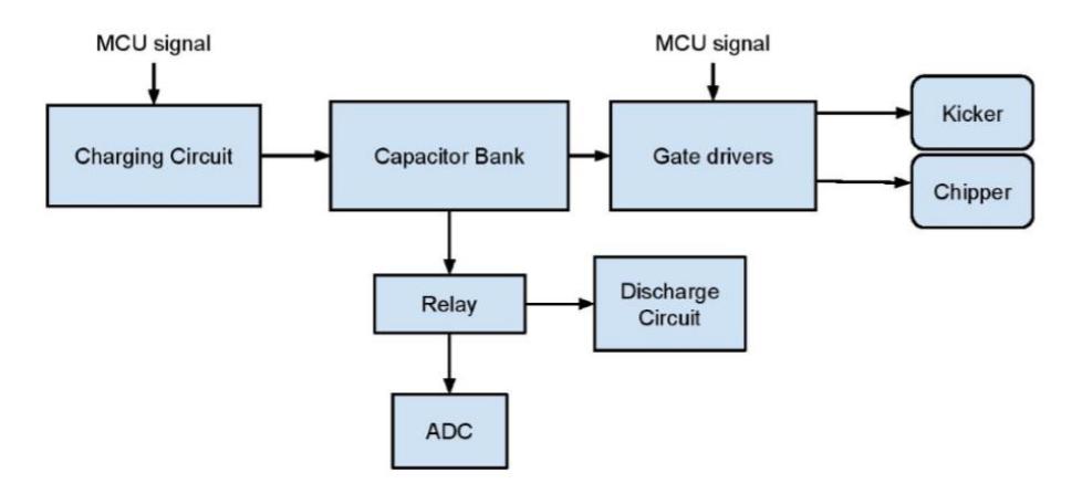
Both kicking and chipping actions operate by discharging a 4 mF capacitor bank charged to 240 VDC, as shown in Figure 2. At such high voltages, safety becomes a serious concern, especially if the charge state of the capacitors is unknown after an unexpected shut down. During normal operation, the capacitors are discharged through the kicker and chipper solenoids in a few seconds. Conversely, in the event that the robot is shut down unexpectedly while the capacitors are still charged, an on-board relay switches the capacitors to a discharge circuit in order to dissipate the power.
In the past year, a large high-power resistor was used to dissipate the power. However, this resistor would fail after a few seconds. In addition, no indication was provided by the circuit as to the current state of the capacitors. In order to address this issue, we have replaced this resistor discharge circuit with a new indicator circuit. This circuit consists of an LED in parallel with a shunt resistor, which is then in series with 2 highpowered resistors. The LED remains significantly visible at 60V and the high-powered resistors are capable of discharging the capacitors without overheating.
Furthermore, we removed a 1 mF capacitor from the capacitor bank. This allows the capacitor bank to charge and discharge at a faster rate, thereby dissipating less power through the indicator circuit. The removal of the 1mF capacitor provides the additional benefit of creating more circuit board space. Currently, the board must be placed offcentre to accommodate solenoid connectors. There are plans to move these connectors down the side of the board in order to provide this space.
3.2 Controller
After the introduction of the movement primitives framework as described in our 2015 TDP [1], we have been focused on improving the performance of each primitive. Our current design consists of six primitives:
- Move
- Dribble
- Shoot
- Catch – Pivot
- Move-Spin
Move: The Move primitive relies on a positional controller which obtains positional feedback from the dead reckoning unit on the robot. With dead reckoning data, the robots calculate a trapezoidal velocity profile to reach its destination. To avoid jittery motion caused by sudden changes in velocity, we limit jerk by averaging desired velocities within a time window. Currently, the Move primitive performs acceptably, although improvements could be made to its accuracy.
Dribble: The Dribble primitive is to be used when the robot detects the ball in its dribbler. The purpose of separating the Dribble primitive from the Move primitive is to allow the robot to use a different drive controller designed for ball retention. However, presently the Dribble primitive still relies on the same positional controller as the Move primitive. In the future, we hope to develop a separate controller optimized for ball retention. Furthermore, this year we are planning to experiment with a constant-velocity controller for the dribbler.
Shoot: The Shoot primitive is a type of specially handled movement that takes into account the proximity of the ball to the robot and the importance of angular accuracy during shooting. In the past, we have always relied on a combination of camera data and forward simulation via a Kalman filter to close the position controlling loop. However, the relatively low resolution of the camera and various errors introduced by the geometry of the camera set-up prevents us from obtaining an accurate distance between the robot and the ball. Additionally, the delay in the camera data sometimes causes our robot to oscillate when it tries to aim with a very small angular tolerance. The Shoot primitive attempts to combine lateral position sensor, as noted in our 2015 TDP [1] information with the improved angular accuracy of the robot level controller. We hope to report a better shooting accuracy in the coming competition.
Catch: The Catch primitive is to be executed on plays where the robot needs to receive the ball from another robot. This primitive is in a raw state compared to the other primitives, and work this year has focused on making it more functionally useful. The idea is to move and rotate to a given position where the ball is going to be, while at the same time moving with a constant velocity along the axis of incidence of the ball velocity. Completing this primitive will allow our artificial intelligence to make more complex plays, and will make our team more competitive.
Pivot: The Pivot primitive can be broadly defined as moving in an arc, an with an arbitrary radius, arc length and robot orientation. This primitive is especially useful when a robot needs to navigate quickly around a stationary ball. The derivation of this primitive is slightly non-trivial but essentially involves mapping position, velocity and acceleration from a Cartesian coordinate system to a polar coordinate system and then back to another Cartesian coordinate system. We found the resulting motion from the robot level arc trajectory planner very accurate and smooth.
Move-Spin: The Move-Spin primitive is intended to be a defensive, fore-checking primitive. The primitive is similar to the Move primitive, in that it moves to a given positional coordinate. However, the robot spins at a specified angular velocity in order to knock off the ball from opposing robots. The coordinates from our dead reckoning system need to be continuously rotated to ensure that the robot continues towards its required destination. This year, we are working on refining the primitive to ensure it travels more precisely towards the required position, and has smoother control over its angular velocity.
4 Software
4.1 Implementation of Coroutines into High-Level Software
This year, we are expanding upon the schema proposed in CMDragon's STP: Skills, Tactics and Plays for Multi-Robot Control in Adversarial Environments [2], which has been in use for several years by UBC Thunderbots. Shortcomings of the previous stateless implementation included an inability to easily and effectively write procedural code due to the need to reprocess the playing field and re-evaluate decisions every tick.
In order to alleviate these concerns, we are using the Boost Coroutines library to develop a solution by implementing the Plays and Tactics layers of the STP paradigm as stateful coroutines that save the execution context across ticks. In coordination with our recent switch to Movement Primitives as described in last year's paper, C++ deterministic destruction will be used to manage the execution of primitives on the Tactic layer.
Firstly, as further development on the movement primitives, each robot will have a queue of movement primitives on the software side. This will enable our navigator to perform "look-ahead" and perform cooling on disjoint paths - that is, rounding off sharp corners - to allow our robots to reach their final position faster. The construction of a "primitive" object in the Tactic layer places a primitive on the robot queue, and its destruction removes it from the queue. Our Navigator layer then accesses this queue to plan out movements. On the Tactic layer, primitives will be queued sequentially, yielding from the coroutine as necessary if waiting for a certain field condition is necessary. An example of using this framework is presented below.
void MyTactic::run(Robot& bot) {
Primitive::Move prim1(bot, target, angle);
// yields from the coroutine until condition is met
wait_condition(goal_empty);
Primitive::Move prim2(bot, target2, angle2);
Primitive::Shoot prim3(bot, goal);
// wait until the primitive is finished
wait_finished(prim3);
}
The wait condition and wait finished methods yield from the coroutine to pass control back to the caller, allowing processing of the other robots to occur. Notably, primitives can also be allocated on the heap to control their en-queueing and de-queueing with greater flexibility.
The Plays layer will perform a similar duty. However, instead of queueing primitives onto execution queues, Plays will control the delegation of Tactics to players in the same manner - they can wait for Tactics to complete before assigning new Tactics to other robots.
In this framework, the Navigator takes up much of the work of handling the primitive queue. As it is at a lower level than the Play and Tactic layers, this makes it much simpler to write new Plays and Tactics as the finer details of execution are increasingly abstracted away. We hope to finish this framework by RoboCup 2016 and test out basic movements and tactics during the competition.
4.2 Optimal Ball Intercept
This year we are improving upon the old interception methods by allowing the AI to dynamically decide the best place to intercept. Instead of simply getting in front of the ball as fast as it can, the intercepting robot will now consider other factors to help it decide where to intercept the ball.
Hopefully this will improve the decisions made after the intercept and help the robots transition from defence to offence. This change will be more noticeable and effective with the shift towards double-size fields, since there will be more space and options for the robot to consider and take advantage of.
This new feature will work by finding both the earliest and latest locations the robot could intercept the ball, and creating an array containing a certain number of points on the line between these locations. The latest location the robot could intercept the ball is considered to be either where the ball is projected to leave the field, where it collides with a player, or where it is predicted to stop - whichever happens first. This array of points is then passed to the evaluation function which returns the most optimal point to intercept at. The evaluation assigns each point a score based on how optimal a point it thinks it is, with higher score representing more favoured points. The evaluation is planned to consider the time it takes to get to the points, how close enemy robots are to the same points, and how many potential shots or passes can be made from that point. Each factor will have a predefined weight in the scoring process, with time and enemy threat being heavily weighted so the robot has the best possible chance of should always beating the enemy to the ball. The potential passes or shots will then be used to differentiate between the remaining points. This new approach should improve the play-making of the team during transfers of possession and allow us to make the best decisions while still beating the enemy to the ball.
4.3 Linear Ball Path Extraction
Currently, the robots have no method of estimating precisely where the ball will stop when moving in a straight, uninterrupted line. To solve this problem, we made a program to extract the data of uninterrupted ball movement from previous game logs. Using the time, x-velocity, and y-velocity from the game logs, we create a new data log with the direction, speed, and acceleration of the ball. By using a linear regression model to graph acceleration as a function of speed, we can estimate where the ball will be in x seconds.
The most important function of this program is the improvement it would provide for passing and intercepting. Currently, much of the software assumes that the ball is moving at constant velocity, neglecting the external forces that will cause it to accelerate or decelerate over time. Thus, the AI is not calculating the most efficient position the robot should move to receive a pass or intercept an enemy pass. By accurately predicting the path of the ball, we save time by providing an accurate initial calculation instead of recalculating based on where to move from positions provided by each tick data.
One long term goal of extracting the behaviour of linear ball paths is machine learning. Essentially, we want the AI to recognize common enemy passes by observing commonly recurring linear paths of the ball in the game. By observing the state of the field before common passes such as enemy positions, we can store certain states to watch out for. Upon recognizing such states, we can predict and begin moving to intercept common passes before they happen. Ultimately, this function would greatly improve defence.
4.4 Movement Primitive To Turn While In Possession Of The Ball
The current movement primitives, though sufficient for general robot motion around the field, do not control the case of a robot needing to turn while in possession of the ball. This results in an imbalance of forces and causes the ball to accelerate out of the robot's control. During a typical turn, the robot faces inward along its curved path of motion. This means the forces acting on the ball (the field's friction and the normal force from the robot) are opposing vectors along this path with no component to oppose the centrifugal force generated from the turn.
The proposed solution is designing a new movement primitive that will orient the robot at an angle inside its curved path, introducing an inward facing component to the normal force from the robot driving the ball, which will provide enough force to keep the ball from accelerating out of control [3]. This angle is to produce the correct cancellation of forces based on the angular velocity.
4.5 Kalman Filter for Position Tracking
One problem with relying on dead reckoning for positioning the robots is the constant need to readjust to a new path. The cumulative error present in dead reckoning can lead to seemingly erratic movement and sometimes difficulty precisely following a straight path. One method used by many systems to smooth out noise in a system is a Kalman filter, which makes use of the sensor's measurements, previously estimated locations, and control inputs into the system to provide both an estimate of the value and standard deviation of the current state of the system.
The general idea in this system is to use the position and velocity of the robots as state variables for the Kalman filter. This provides an estimate of the current state variables which can be used to determine the controller inputs needed to follow a path. The Kalman filter would be implemented on the micro-controllers for each robot for ease of access to its own state variables and encapsulation.
A missing implementation detail is the lack of compensation for the quarter second delay from the camera loop for estimating the position of robots. The uncertainty in position caused by the camera delay will ideally be reduced by extrapolating from a state velocity estimation, and will then be absorbed into the Kalman filter's uncertainty matrix. Further investigation is needed to see if the delay poses enough of a problem to consider improving the implementation in this way.
The goal of adding a Kalman filter is to improve the accuracy of the computed positions and velocities of the robots. An increased performance in navigation and tracking allows for more consistency in tasks such as passing and allows for the introduction of more complicated passing plays.
5 Conclusion
We believe that the design changes detailed above will lead to significant improvements in performance. We look forward to putting the changes into action at RoboCup 2016.
6 Acknowledgements
We would like to thank our sponsors, as well as the University of British Columbia, specifically the Faculty of Applied Science and departments of Mechanical Engineering, Engineering Physics, and Electrical and Computer Engineering. Without their continued support, developing our robots and competing at RoboCup would not be possible.
References
- S. Churchley, R. De Iaco, J. Fraser, S. Ghosh, C. Head, S. Holdjik, N. Ivanov, S. Johnson, F. Kalla, A. Lam, B. Long, K. Lu, S. Ng, K. Peri, J. Petrie, E. Roach, W. Y. Su, B. Wang, C. Xi, K. Yu, and K. Zhang, "2015 Team Description Paper: UBC Thunderbots," 2015.
- B. Browning, J. Bruce, M. Bowling, and M. Veloso, "STP: Skills, Tactics, and Plays for Multi-Robot Control in Adversarial Environments," Proceedings of the Institution of Mechanical Engineers, Part I: Journal of Systems and Control Engineering, vol. 219, no. 1, pp. 33–52, 2006.
- J. Biswas, P. Cooksey, S. Klee, J. P. Mendoza, R. Wang, M. Veloso, and D. Zhu, "CMDragons 2015 Extended Team Description Paper," 2015.