Description of the Warthog Robotics SSL 2016 Project
Rafael G. Lang, Guilherme C. de Oliveira, Henrique B. B. Menezes, Nicolás dos S. Rosa, Rafael A. Correa, Victor H. Gomes, Ivan N. da Silva, Roseli A. F. Romero
Warthog Robotics University of São Paulo at São Carlos
Abstract This paper presents the main modifications since the last Team Descrition Paper of Warthog Robotics and a general explanation of the current project, presenting RoboCup SSL team WR Magic, developed since 2011 by the Warthog Robotics group from the University of São Paulo at São Carlos. This project merges the best features from older projects developed by the groups GEAR and USPDroids. The mechanical structure is a mixed design using aluminum and composite materials and contains four DC motors for locomotion. The system architecture is based on the GEARSystem library, with a new decision tree strategy module, and powered by some filtering algorithms on the vision module. The team presents full game capability with accurate and fast responses to strategy and referee commands.
1 Introduction
At the beginning of 2011 the groups GEAR and USPDroids merged creating the Warthog Robotics, a group of the departments of Electrical Engineering of the São Carlos School of Engineering and the Computer Sciences of the Institute of Mathematics and Computer Science of the University of São Paulo at São Carlos. The group counts with about 60 members students of Computer, Electrical and Mechatronic Engineering and Computer Science and develops robotics technologies, applying most of them at the robot soccer.
The mechanical structure and the electronic boards are the same from the last year, described briefly on this paper, and detailed information can be found in [1]. The next sections presents the newest modifications of WR Magic features details, most of them on the computer systems (artificial intelligence and computer vision systems).
2 Mechanical Structure
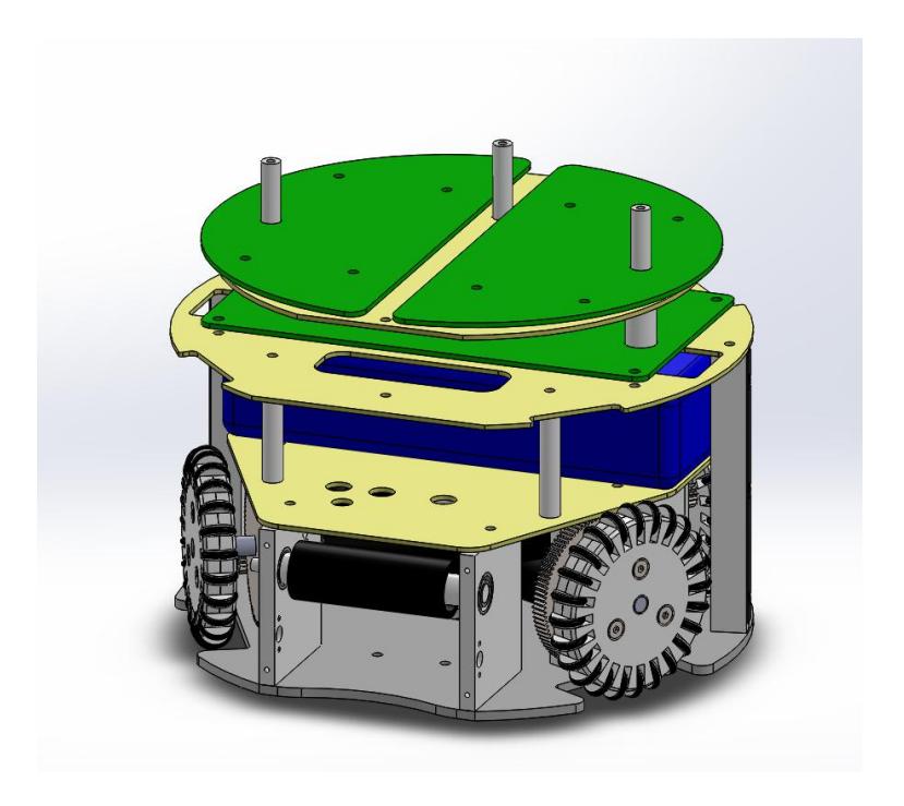
The mechanical structure is exactly the same of the last year, accommodating the locomotion system with its four Faulhaber 2342 DC motors, the kicking device, and the dribble device mounted with shock absorber system and linked to another Faulhaber 2342 DC motor. The upper part houses the three electronic boards, the battery and the kick capacitor using glass fiber plates; and the cover is a front cutted cylinder with protected wheels and oppenings for the kicking and dribble devices. All mechanical structure is made of aluminum and composite materials as shown in figure 1.
3 Electronic Devices
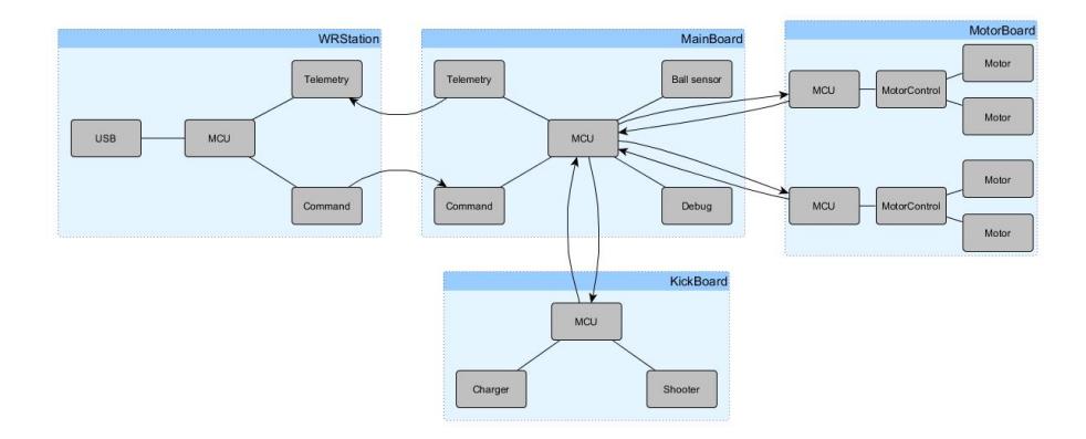
The eletronic devices is the same of last year, composed of three electronic devices: MainBoard, MotorBoard and KickBoard. The architecture of the embedded electronics is shown in figure 2.
– The MainBoard is responsible for receiving commands, decoding them and sending commands to the requested actuators (motor board, dribble device and kick board); and for measuring information to send them back to the telemetry system. All communication is done by the transceiver nRF24L01+ [2].
- The MotorBoard receives commands from the MainBoard and controls the motor speeds using the 512 lines per revolution Faulhaber IE-2 encoders as a feedback of a classic PID controller. The controlling is done by two L298 ICs, activated by PWM, an easy to implement solution and, according to [3], ensures that "the global efficiency of the system, even when taking the losses due to harmonics into account, is much larger than the one provided by linear amplifiers".
- The KickBoard controls the kicking device, charging the capacitors and discharging them in a custom solenoid when requested. The charging module follows the boost topology with a digital control system, as described in [4], [5], and [6].
All boards are powered by a four cells LiPo battery of 2.6 Ah, that provides an autonomy of about 30 minutes to robot in a game-like ambient.
4 Computer Systems
The WR Magic Project software is now based on five sub-projects developed by the group: the GEARSystem library, the WRBackbone server application, the redesigned WRCoach strategy application, the newest WREye vision filtering application, and the newest WRStation radio communication application.
4.1 GEARSystem
The GEARSystem, same used the last years, is a distributed system library that provides communication among all system modules [7]. It is built over CORBA and allows a distributed execution of the modules.
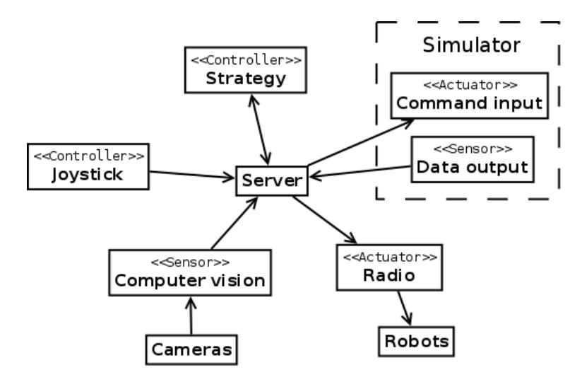
The library architecture is minimalist, with four basic elements: Server, Sensor, Controller and Actuator. The sensors can create teams, players and balls and set their information (position, orientation, velocity, etc). Controllers may read these information and send commands to the actuators (move, kick, dribble, etc). Actuators read, decode these commands and execute them. The Server connect all those elements. This architecture allows the easy development of new softwares based on the four main modules, as shown in figure 3.
4.2 WRBackbone
The backbone is the Server module on the GEARSystem architecture. It doesn't have any significant function other than acting as the server that connects all modules.
4.3 WRCoach
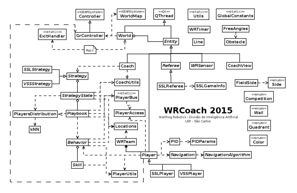
The coach is the Controller module on the GEARSystem architecture and is responsible for setting the strategy to the team. A simplified snippet of the software architecture is presented in figure 4. The subsequent paragraphs describes the Coach architecture with some details; a full description of the software is available in Brazilian Portuguese at [8].
The main strategy hierarchy is a decision tree composed by Strategy, StrategyState, Playbook, Behavior and Skill. It is similar to last year strategy architecture, but now new auxiliary modules were developed to fulfill new requirements. Each strategy implementation has 11 strategy states based on referee states. When a strategy is running, it analyzes the referee state and executes the corresponding strategy state (a state machine that changes strategy state based on referee). Each strategy state implements a global behavior based on the current ambient and sets plays to group of players. Each play, which is a group of players, sets individual behaviors for these players.
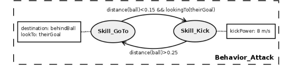
Each player in the field is part of a play, and has a individual behavior that, using low level implementation of simple actions called skills, perform actions on the field. The figure 5 shows an example behavior (attack behavior) state machine of skills.
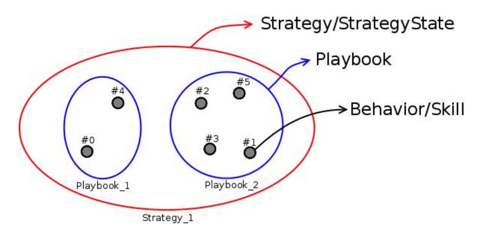
All attributions are flexible: during the game, the strategy can choose the best set of plays, which, in turn, can choose the best set of behaviors for the game situation. Each layer on the strategy hierarchy handles a group of players, or a player, as shown by figure 6.
The AI implemented as plays (group of players performing some action): DoNothing, FollowBall, Positioning, Attack, Defense, GoalDefense, OurKickOff, OurPenalty, and TheirPenalty.
The AI implemented as behaviors (a players performing some action according to a play): DoNothing, FollowBall, Positioning, Attack, Goalkeeper, GoalkeeperAssistant, MarkBall, MarkBallAssistant, MarkPlayer, PenaltyAssistant, PenaltyGoalkeeper, PenaltyKicker, and PassReceiver.
The AI implemented as skills (a minimal action that compose a skill): DoNothing, GoTo, InterceptBall, Kick, PushBall, and Takeout.
The PlayersDistribution and kNN modules helps the strategy hierarchy to select and assign plays/behaviors to the players in the field. The kNN sorts the available players in the desired way, like a) distance to an arbitrary position, or b) Y-axis of the field (vertical). The PlayersDistribution module ensures that each player is selected by kNN only once per iteration. This way, the strategy hierarchy can work with dynamic number of players just by calling the kNN in the right order (essentially, prioritized by importance of that player to current game state; for example, in a direct kick, the first player to be assigned to a play/behavior is usually the kicker).
The Utils, CoachUtils and PlayerUtils modules is a set of functions to help in development: a) Utils, player/team independent functions (for example: distance between two points); b) PlayerUtils: player dependent functions (for example: free path to another player identified by id); and c) CoachUtils: team dependent functions (for example: nearest opponents to position).
The PlayerBus and PlayerAccess modules act as a bridge between players, allowing data to be exchanged between teammate and opponent players existing in the system. An interesting feature of PlayerBus is that it allows one player, using the bus, to access other players' (teammates or opponents) information in that player's perspective. The information's exchanged can be as simple as the player's position, or a complex utils function like a free angle to the goal in that perspective.
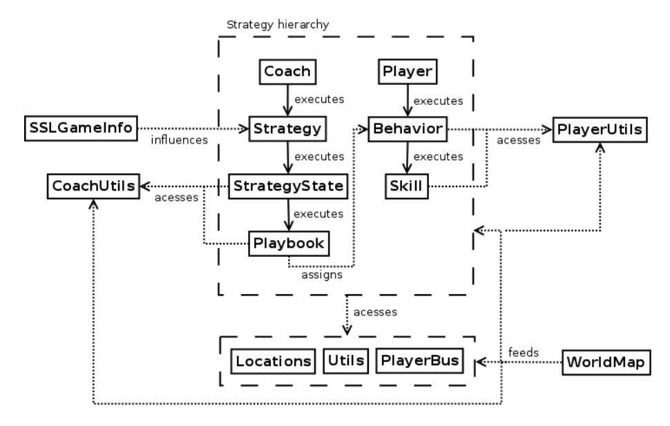
The figure 7 shows the execution flow and interations in the multiple modules of the strategy hierarchy.
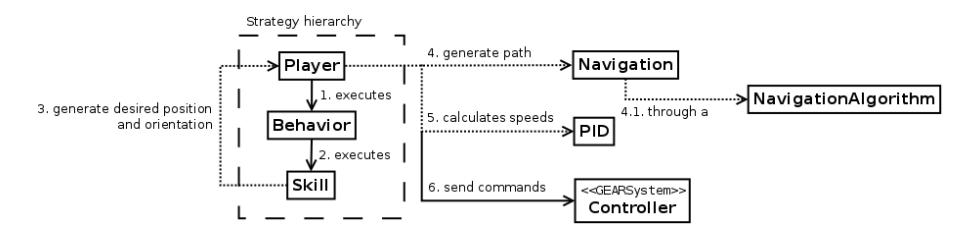
The PID/PIDParams and Navigation/NavigationAlgorithm modules implements the control algorithm (a classic PID controller) and navigation algorithm (path planning, obstacle avoidance, etc), respectively. The navigation uses the simple potential fields technique. This technique uses the goal position as an attractive force and obstacles as repulsive forces, getting a resultant force that is the navigation direction. Each robot compute its navigation direction individually. The execution flow of a player entity is shown in figure 8.
The other modules are complements to the whole system.
4.4 WREye
The eye is the Sensor module on the GEARSystem architecture and is responsible for receiving the data from ssl-vision software, filtering the data, and inserting it on the system.
It is basically composed by the following filters:
- Kalman Filter: responsible for filtering position information and computing velocity of the objects in the field.
- Noise Filter: responsible for filtering erroneous noise information (for example, a robot that was detected only for a few frames as noise in a pattern).
- Loss Filter: similar to Noise Filter, responsible for filtering missing robots that may blink on the detection.
- Multi Object Filter: responsible for unifying duplicated robots detected by the multiple cameras.
4.5 WRStation
The station is the Actuator module on the GEARSystem architecture and is responsible for sending the commands generated by WRCoach to the robots. It essentially connects via USB using QtSerialPort [9] to a custom station board that reproduces the commands wireless.
5 Improvements for 2016
The mechanical and electronic projects are the same from 2015.
The new three-tier control model for the robot still under development with one controller for the robot's velocity, one motor speeds and high-level one for the AI modules. In order to design a robust controller, complete models has to be created, considering several aspects of the robot's kinematic and dynamic. By the time of the writing of this TDP, the models were developed and are in phase of validation.
The presented WRCoach structure is completely new and allows more control over the AI components, facilitating the coding execution. Also, the WREye evolved from a simple "best confidence" software to a resourceful filtering application.
6 Conclusion and Future Work
The presented project brings a whole set of improvements, mostly on the computer systems, taking the group to a highly competitive level. The developed hardware is robust, reliable and provides an excellent platform to the strategy systems. Until mid-2016 the computer systems shall be tested harder and some new features may be available either on navigation and strategies or on integration systems.
7 Acknowledgments
The authors would like to thank all Warthog Robotics team for the help and friendship; the University of São Paulo for the facilities and financial support; the Griffus, Embraer, Jacto, HOMIS, Arbor, Bauru Ferramentas and ALLTEC companies for the technical sponsorship; and all others that helped us during the project.
References
- Lang, R.G., Bernardo, A.M., Oliveira, G.C., Menezes, H.B.B., Ramos, L.C., Roque, L.G.S., Silva, I.N., Romero, R.A.F.: Description of the Warthog Robotics 2015 project. In: 2015 RoboCup (2015)
- Nordic Semiconductor: High Frequency 2.4 GHZ Wireless Transnciever. Data Sheet (2007)
- Olivera, V.A., Aguiar, M.L., Vargas, J.B.: Sistemas de Controle Aulas de Laborat´orio. EESC-USP, Brasil. (2005)
- Pressman, A.I.: Switching Power Supply Design. McGraw-Hill. (2003)
- Mohan, N., Undeland, T.M., Robbins, W.P.: Power Electronics Convertes Application and Design. Wiley (2002)
- Tse, C.K.: Complex Behavior of Switching Power Converter. CRC Press. (2003)
- Lang, R.G., Romero, R.A.F., Silva, I.N.: Development of a Distributed Control System Architecture. In: 2014 Latin American Robotics Symposium. (2014)
- WRCoach v2 documentation. Division of Artificial Intelligence Warthog Robotics, available at https://www.assembla.com/spaces/warthog-dia/wiki/WRCoach_v2.
- Qt Company: QSerialPort documentation, available at http://doc.qt.io/qt-5/qtserialport-index.html.