ZJUNlict Extended Team Description Paper for RoboCup 2016
Lisen Jin, Lingyun Chen, Xiaoxing Chen, Yachun Li, Weijian Hu, Rong Xiong
National Laboratory of Industrial Control Technology Zhejiang University Zheda Road No.38, Hangzhou Zhejiang Province, P.R.China
http://www.nlict.zju.edu.cn/ssl/WelcomePage.html
Abstract ZJUNlict has been participating in Robocup for about ten years since 2004. In this paper, we summarizes the details of ZJUNlict soccer robot system we have developed in recent years. we emphasize on the main ideas of designing the robots hardware and our software systems. Also, we will share our tips on some special problems.
1 Introduction
Our team is an open project supported by the National Lab. of Industrial Control Technology in Zhejiang University, China. We have started since 2003 and participated in RoboCup during 2004-2014. The competition and communication in RoboCup games benefit us a lot. In 2007-2008 RoboCup, we were one of the top four teams in the league. We also won the first place in Robocup China Open in 2006-2008 and 2011. We won the first prize in 2013 and 2014, which is a great inspiration to us. Also, we incorporate what we have done in recent years in this paper.
Our team members come from several different colleges, so each member can contribute more to our project and do more efficient work.
2 Hardware
(This is a section header containing subsections)
2.1 Mechanical Improvements
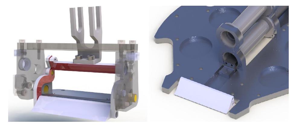
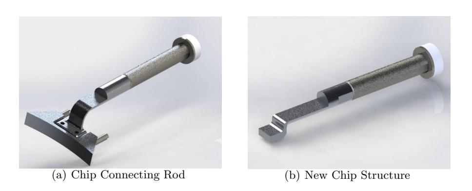
In last year's competition, we encountered with problems about the chip connecting rods' [Shown in Figure 1 , red components] looseness, damage and deformation due to high frequent action. In order to avoid it from happening again, we replaced the old parts with higher yield strength materials this year. In the meantime, we are developing new structures to directly impact on chip kicker instead of using connecting rods structure. [Shown in Figure 2] Several experiments have been conducted to optimize the new structure. We hope it will perform well both in chip distance ability and improve its lifespan.
Following are several main improvements in the new structure:
I This year we have redesigned the kick module [Shown in Figure 3 (a)] and the chip kick module [Shown in Figure 3 (b)]. New structure which can directly impact on chip kicker are developed to replace the connecting rods structure used before. We connect the iron core plunger with the chip kick rod. With electromagnets driving the iron core plunger, the rod of the chip kick module impacts on the chip kicker, then the chip kicker kicks the ball. Compared with the connecting rod structure, the efficiency of the new structure with impacting is much higher. Because the chip kick module is in the lower position, we move upward the kick module properly, in order to ensure the position is unchanged where the kicker kicks the ball. We also design the integral kick rod, as well as the embedded kicker.The new structure of the kick module and the chip kick module lower the vehicle's center of gravity, which makes the vehicle running more robustly. This can effectively prevent the vehicle from turning over.
II We have improved our coils by using ANSYS ANSOFT simulating software. The original coils used 0.80 mm diameter copper wire which weights so heavy that may affect the flexibility of the vehicle. The new coils use 0.56 mm diameter copper wire. The new coils weight reduces to about 100g. Through the velocity experiments, we are delighted to discover that the new coils can guarantee the same speed as the original ones.
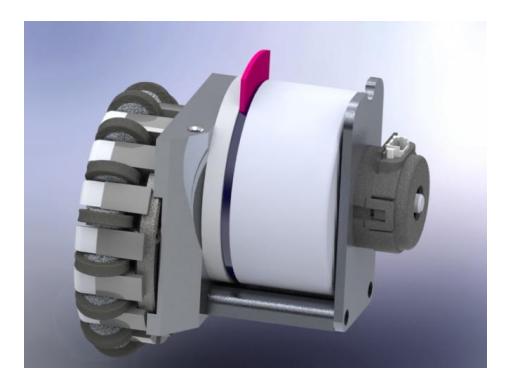
III We change part of the vehicles motors to 70w to improve the vehicles power. In spite that the weight is increased by doing so, the relatively low center of gravity, to some extent, stabilized the vehicles. Adapting to the larger size of 70w motors, we adjust the position of two rear wheels encoder stents. We moved them from motors side to the position that under the two motors. Meantime, we adjust the corresponding hole sites on the motor mounts [Shown in Figure 4]. In this way we can make sure no interference between the front motors and rear motors.
2.2 Fully Independent BLDC Motor Drive Pack
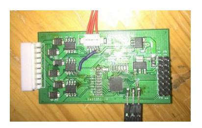
Last year we successfully separated the motor control circuit, in order to improve the interchangeability between the modules. During the improvement we found that the control logic and algorithm which were still left in the center control processor is complex and inconvenient. So this year we decide to integrate the control logic and algorithm into the independent motor drive module and make it a more complete BLDC(Brushless Direct Current) Motor drive pack[Shown in Fig 5]. The differences can be listed as follow:
I A low-cost MCU(Microcontroller Unit) was added to the module to control one single motor only. Compared with the old solution which uses FP-GA(Field Programmable Gate Array) to decode the hall sensor and incremental encoder, our new solution does not need gates to change the signal voltage from 5V to 3.3V. Besides, the MCU has integrated an ADC(Analog to Digital Converter) on chip, thus the ADC device on board can also be given up.
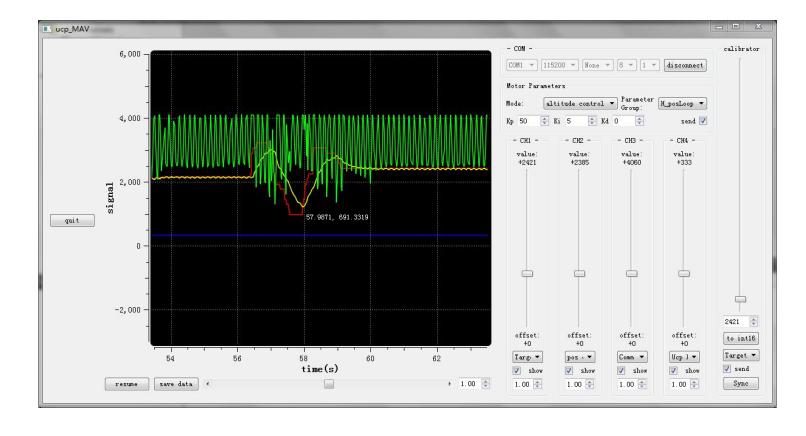
II On-line motor controller development platform. We developed a GUI(Graphical User Interface) for PID(Proportion Integration Differentiation) parameters tuning, motor response curve observing and motor body parameters calibration[Shown in Fig 6]. The GUI communicates with the motor driver by our self-developed protocol, which is efficient and is not restricted to hardware interface, such as RS485 or CAN. We also built a real time BLDC motor model to test the calibration interface.
III The MOSFET on board was changed to a smaller one, in order to reduce the size of the module.
2.3 Processor Improvement
In the past years, linear open-loop motion in y axis direction wasn't accurate. Therefore, we want to find out the source of the problem by monitoring bottom control signal. However, we couldn't add a monitor module due to the deficit of the logic elements, which also limits other electrical improvements. To break this limit, we tried to solve the problem in two ways:
I Considering about compatibility with former edition, we tried to upgrade the FPGA controller by ready-made core board within Altera Cyclone Family, such as the LUTs. Although we eventually found a promising board, it didn't work with our system in experiments. Thus, we abandoned this approach.
II The second way is to simplify FPGA system frame to make room for further improvements. To achieve it, we cleared the redundant parts existing in our system and refactor all bottom control code. We rebuilt Quartus II and NIOS II software programming environment as well. Now we successfully finished this part and the improvement for correcting velocity in y axis direction is processing.
In order to adapt the fully independent BLDC motor drive pack which is described in section 2.2, We transplanted our embedded communication software to a new processor based on a MCU with ARM Cortex-M4 architecture. The new processor meet demands perfectly and is much cheaper than Altera FPGA.
2.4 New Power Supply Subsystem
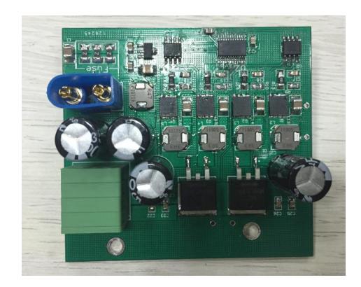
Previously, we used lithium battery to power the motor directly. This power supply approach has several disadvantages. The output voltage is unstable over time and fluctuated current is bad for discharging efficiency and the lifespan of battery. For these reasons, we designed a new power supply subsystem for motors. The rated power of the new subsystem is 300W, and the rated current is 20A. In order to enhance the ability of moment-over-loading, we adopted a 4-phase boost converter. When the power supply subsystem output at 300W, the conversion efficiency is more than 90%, and the main peak frequency of ripple is 50MHz, based on demo board[ Shown in Figure 7]. We hope we can integrate the subsystem in our robot this year.
2.5 Improvements in offline-test-mode
In order to improve the convenience of testing our robots, we modified former offline-test-mode. To be more specific, we need to test our robots to confirm they can communicate well with transmitter in certain frequency without sending the testing packet via computer. Thus we added offline communication tests to the offline-test-mode. In this new mode, robots can automatically communicate with the computer and tell us the test result through the LED.
2.6 Speed decomposition using 3 motors
The speed in the direction of x axis, y axis and rotation axis which are sent to the robot will be decomposed to 4 motors normally. when 1 of the motors failed in some situations, the direction of resultant speed of all the motors are incorrect. With the feedback of vision, the track of the robot will become out of control. We can detect the failure by the difference between encoder signals and hall signals.
To solve this problem, we decomposed the speed using 3 motors. There are 3 target parameters, speed in x axis, y axis and direction of rotation. We can also set 3 another parameters, the speed of 3 motors, then list equations including 3 unknowns. By solving these equations, we will get a proper speed to set other the 3 motors and make the robot more controllable.
The approach described above still has many bugs, for example we didn't consider the resistance from the failure motor. But we believe it is a promising attempt. We will do more motors test to fix these bugs and make it more practical.
2.7 Design of new transmitter
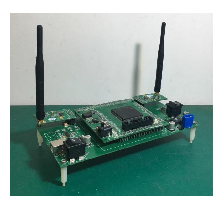
In the past versions of our transmitter, the sending and receiving modules were too close to each other. Through our communication tests, it may caused a higher package loss rate when the communication between the transmitter and robots was undertaken. To improve this, we build a new version of transmitter in which nrf2401 modules (communication module) are set as far from each other as they can be[Shown in Fig 8]. We observe a decrement in package loss rate compared to the former version of transmitter in the same condition. Besides, we also add several extra functions to new transmitter so as to provide the communication system with a more stable connection. It states as follows:
I We add an RS232 interface instead of simply using USB-B interface to power up and transfer data between PC and transmitter all the time. We can select one of them to transmit data through a dial switch.
II In the past, we only used USB to power up our transmitter. In this new version, we can choose from a 16V battery and the USBs power by changing states of rocker switch. This will offer us a more steady power source if we choose battery, because sometimes power supply from USB may be disconnected suddenly which is fatal to communication process.
III For convenience, we put a rotary switch in the new transmitter as an assistant part for transmitter mode selection. We do not need to set transmitters mode through serial port but can modify it by switching this component.
IV We also change controllers model. We used to use Altera Cyclone I to control transmitter which seemed to be too outdated now. So instead, we transplant our system to Altera Cyclone model and replace former controller with it.
3 Software
(This is a section header containing subsections)
3.1 NormalPlay2016-New generation play
NormalPlay2016 is our first try on new generation of Plays. It deals with the normal state of our game. The normal state means the state not triggered by referee message, it is important for RoboCup-SSL game since the field is larger than before and the technique of teams are all improving, thus we developed NormalPlay2016. When developing a Play based on FSM, we used to consider all the possible states (or as much as we could) and conditions to enter or exit these states. But for our new generation play, we no longer develop in this way. By using learning module and state evaluation module based on Bayesian theory, NormalPlay2016 can itself generates all the possible routes and assign all the tasks automatically. To be more concise, what old plays doing was choosing, but new plays doing is thinking.
A brief working process of NormalPlay2016 is:
I Evaluation of the state of the game and assign the ration of attack-defend. For example, when there is little threatening and the possibility of successful shooting of our team is big, the ration would be 5-0 or 4-1 (considering one robot always for goalie, thus in a-b, the sum of a and b is the total robots number of our team minus one).
II Generating all the attack routes and defend routes.
III Evaluation the possibility of successful attacking routes and successful defending routes based on Bayes theory, and choose the optimal route.
IV Evaluation the optimal route and decompose it to Skills of each robots, then assigning all these Skills to robots.
3.2 Parameters feedback adjust
In the previous sections, we have introduced that our system is based on Play-Skill frame. The Play decides what the team should do and the Skill decides what the specific player should do, that is, the aim of a Play is to make the system intelligent and the aim of Skill is to make the robots movement more precise.
Inside the cpp of a Skill there are many parameters. And these parameters may sometimes dramatically influence the performance of the whole system. During our previous years development of our system, we used to adjust all the parameters by ourselves before games. However the problem is the job is both tiring and time consuming. Furthermore, since the physical environment is different between different fields, even though our robots work out fine in our own field, in other fields it may not work the same way.
Facing all the problems above, we developed a parameters feedback adjust module. It is just like what we learnt from the principle of automatic control. The system will detect the deviation from expected value to real value, and use the deviation to adjust the parameters. We have already applied this module into several Skills for test, and it turned out to be useful. In the future, we will apply this module into our whole system and we do believe this module can improve the performance of our whole system.
4 Conclusion
In this year, we are trying to make a new pattern in the NormalPlay, but we are still working on that. And the paper mainly tells the big changes happened to our hardware designs. We are working in several ways to make our robots more stable and more aggressive. In next year, we will continue to focus on the multi-agent cooperation to make our strategy more intelligent.
References
- Brett Browning, James Bruce, Michael Bowling and Manuela Veloso, STP: Skills, tactics and plays for multi-robot control in adversarial environments
- Yonghai Wu, Penghui Yin and Rong Xiong, ZJUNlict Team Description Paper for RoboCup2011
- Yonghai Wu, Xingzhong Qiu, Guo Yu, Jianjun Chen and Xuqing Rie: Extended TDP of ZjuNlict 2009 Robocup 2009
- Sebastian Thrun, Wolfram Burgard, Dieter Fox, Probabilistic Robotics, The MIT Press