ER-Force Extended Team Description Paper RoboCup 2017
Jonas Bühlmeyer, Daniel Burk, Alexander Danzer, Stefan Kronberger, Christian Lobmeier, Michael Niebisch, Bjoern M. Eskofier
Digital Sports, Pattern Recognition Lab, Department of Computer Science Friedrich-Alexander University Erlangen-Nürnberg (FAU), Erlangen, Germany; Robotics Erlangen e.V., Martensstr. 3, 91058 Erlangen, Germany
http://www.robotics-erlangen.de/
Abstract This paper presents proceedings of ER-Force, the RoboCup Small Size League team from Erlangen located at Friedrich-Alexander-University Erlangen-Nürnberg, Germany.
Introduction
ER-Force has successfully partaken in RoboCup competitions for almost a decade. In this Extended Team Description Paper we would like to present our most recent efforts in improving both our hardware and software. We hope that our remarks support other teams in making Small-Size-League an even faster and more interesting league.
Mechanics
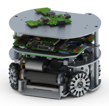
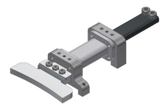
Over the last year we observed an increase in mechanical play of the flat-kick plunger in the kick module. As the described sign of wear could interfere with the ability to execute precise passes or shots on the goal, we decided to redesign the flat kick part of our kick module. The flat-kick design used up until now was drafted for RoboCup 2014 and the involved parts were manufactured before RoboCup 2014 and used since then. In this design, described in the 2014's Team Description Paper [1], the flat kick plunger is supported by a single bearing. Conveniently, this bearing surface is the inside of the hole in our flat-kick solenoid, which is made out of polyamide.
In order to improve the durability the guiding function was transferred to the aluminum solenoid mounting blocks. The plunger is guided in the openings of the mounting blocks instead of inside of the solenoid. We use a flat kick plunger and solenoid with rectangular cross sections, which allows us to lower the position of the kick module. This results in a lower center of mass of our robot while avoiding the need to change the rest of the robot. The new design is shown in figure 1.
Electronics
Adjustments of motor current measurements
To get correct results and make precise statements about our motor currents it is crucial to do the measurements at synchronized times. Since our motors are controlled via PWM signals, there will always be periodically arising transients which heavily disturb our measurements, resulting in an increased effort to trigger the measurement at the right time. To solve this problem the PWM signal as well as the trigger signal for the measurement use the same timer with different offsets. This makes it easier to develop a better motion control.
Optimizing the kicker board
Since the development of our current robot generation we faced a severe problem regarding the kicker mechanism: In some unpredictable and rare cases – yet much too often – the IGBT of our chip kick, i.e. the power transistor controlling the current flow through the chipping coil, which in turn generates the magnetic field that pushes the chip kicker forward, simply fails due to being operated beyond its power ratings.
The biggest issue here is that it is nearly impossible to trigger the problem while doing the required measurements, leaving no clue about what exactly causes the failure to happen. The only thing we do know is that the problem only applies to the chip kick but not to the linear. Making things worse, it isn't that easy at all to redesign the circuit to fit the problem without using larger components, which can't be used as the space available for the whole kicker circuitry is very limited and already used to its maximum. This is the reason why just installing a larger transistor or adding a current limiting resistor in series to the IGBT was never a possible solution to the problem.
After much time spending with theoretically investigating the problem and consulting applicable simulation programs we finally concluded that the real trigger for the failing transistor is a short-term but drastic increase of power consumption by orders of magnitude due to a too slowly closing IGBT.
In depth: As mentioned before, the current through the coil is controlled by the IGBT, which in turn gets its commands, i.e. its gate voltage, indirectly from a micro controller. At the beginning of a shot the IGBT opens because of an increasing gate voltage triggered by the controller. From a physical point of view, the gate gets floated with charge carriers which create the actual gate voltage and act as the transmitters of the shot command.
On the other hand these carriers have to be removed from the gate when the shot gets terminated by the micro processor to ensure the cessation of current flow. But as resistances limit the gate current, opening and closing the transistor won't happen immediately. Instead it's a steady, more or less fast increase or decrease of gate voltage. That means that while switching the IGBT's state from closed to open and vice versa there will always be a short time interval in which the transistor is in a semi-conductive neither open nor closed state.
While this isn't a problem at the beginning of a shot due to the choking characteristic of coils, which prevents currents from rising to its peak value immediately, it will be a big issue when closing the IGBT, as the same effect will prevent the current from immediately dropping to zero. This finally leads to a remarkable and eventually lethal amount of power consumed by the mid-resistive transistor, even though there is a freewheeling diode present.
To solve this problem, we first tried to change the IGBT to one that simply charges faster without it being larger than its predecessor. Although we found some transistors that suited this solution, they all lacked the overall qualification for being used in our robots, as most of them for example couldn't stand the high voltages and currents used.
As we can't solve the problem just by changing the transistor to a model which fits all the required criteria for a good functionality (i.e. a high maximum rating for the reverse voltage, high continuous and peak drain currents, a high max. power and finally a low gate charge), due to the space restrictions, there was no other alternative than to choose the best IGBT that fits our dimensions. But our goal for next year's RoboCup however, is to redesign the kicker circuit so that even the IGBTs fitting our given limitations don't exceed their specifications. This will drastically decrease the amount of time needed for maintenance.
Motion control
Rebuild of the old system
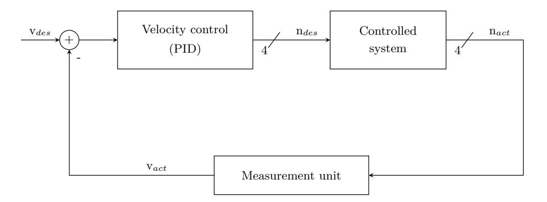
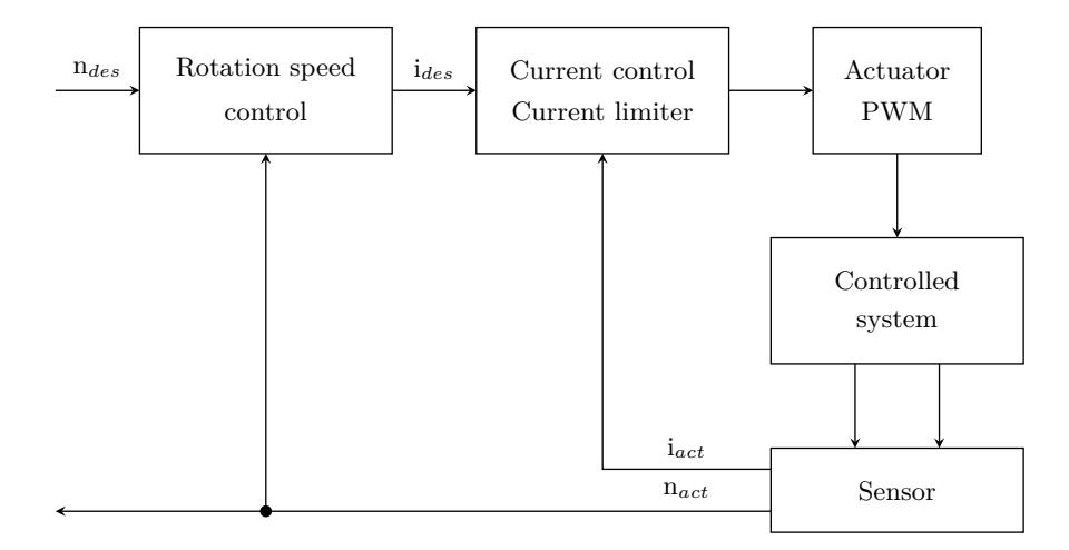
Last year we recreated our complete motion control from scratch. This was due to the fact, that the old system was a nearly not changed for several years. This system was build as simple as possible, so that it was clear, that we can get it to work till the last Robocup. Therefore we used a simple PID–controller implementation, which was fast and easy to implement. The created system is shown in figure 2 and figure 3. With this working system in the background we decided to move further to a more sophisticated motion control, which will help us for example to implement an anti-slipping-regulation.
New control system
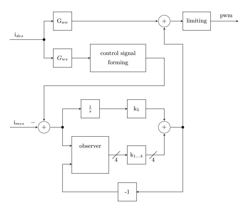
Current controller The current controller is basically an observer based state controller with two degrees of freedom. The first ss the feedforward, shown in figure 4 as the GAW –block. This feedforward ensures a fast reaction time by creating a control signal which allready fits quite good the optimal control signal without a need of measurement, so only a relatively small error has to be compensated by the controller. This feedforward is quite good due to a lot of work in validating and verifying the mathematical model of the electrical machine. The second degree of freedom of the current control is the feedback. First the measured values are filtered due to a high noise in the measurement. The error, calculated by difference between the desired output signal and the measured signal, stimulates an observer and an error model for constant errors. The observer estimates four values, which describe the states of the modeled system. The output of the error model for constant errors and the observer are used as base values for the feedback, so they are multiplicated by factors which were calculated with the Ackermann-formula, summed up and added to the signal from the feedforward. As the feedforward ensures a short reaction time of the whole system to changes in the desired current, the feedback ensures stationary precision. This system is allready created, implemented and working.
Defensive Game
In our preparation for the RoboCup 2016 we completely reworked our defense. Throughout the whole competition, we only received two goals, one each from the current champion MRL and the runner up CMDragons. In the following chapters the general concepts and ideas will be described.
Components
Our defense consists of three main tasks.
- The duel task is responsible for contesting the ball while impeding direct goal shots.
- The manmark task tries to prevent an opponent from scoring a goal by actively following him across the field.
- The center back is the most defensive one and usually moves in close proximity to the defense area.
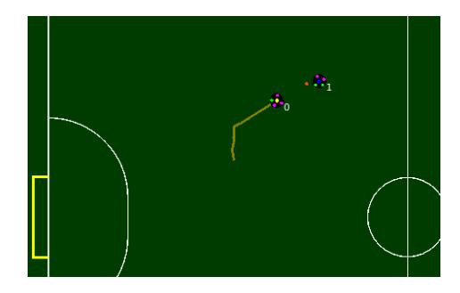
Duel The first line of a good defense is the dueling behavior. Duel means that at least one robot of each team tries to obtain possession of the ball. For the RoboCup 2016 we implemented a very defensive dueling approach. Our main objective is to always prevent a direct goal shot. Therefore, we don't drive directly towards the ball but rather try to block the line between the ball and our goal as fast as possible. Once we reach the line, we head for the ball. This behavior not only limits the time window for the opponent to shoot a goal but also favors clutch saves. Our first try was to drive to the perpendicular between the robot position and the ball-goal-line. We soon realized, that it may be the shortest way to block a shot, but not the fastest. Almost every time our robot has some speed into some direction. Therefor we have to calculate the point to which we can drive the fastest. We implemented a ternary search algorithm as seen in Algorithm 1. The result of this can be seen in Figure 5.

Composition
Depending on the current state of the game, the number of defenders changes accordingly.
Fig. 7. Number of defenders
| game state | number of center backs | number of manmarkers |
|---|---|---|
| offensive corner kick | 1 | 0 |
| offensive throw-in | 1 | 0 |
| offensive goal kick | 1 | 0 |
| dynamic game | 1 | 1 or 2 |
| stop | 4 | 0 |
| defensive goal-kick | 1 | 3 |
| defensive throw-in | 1 | 3 |
| defensive corner kick | 1 | 4 |
In Stop, we draw back all of our robots except one. The reason behind this is that we don't know which referee state comes next. If it's a freekick for the opposing team, they can execute it immediately without us having a chance to react. Therefore, it's best to expect the worst.
Chip kick flight reconstruction and prediction
Generic curve fitting approach
Rojas et al. proposed an approach which calculates the properties of an observed flight based on a curve fitting method[2]. They developed a pair of equations which sets observed ball position measurements in relation to the ballistic trajectory of a projectile. These are based on the intercept theorem.
Application to the SSL-Vision system Coordinates in the original description exist in two coordinate systems, namely a world and a camera coordinate system. Coordinates can be converted between these systems using a rotation matrix and a translation vector. We adapted the equations with respect to the field coordinate system which is used by SSL-Vision[3]. We extended the model which is now capable of using measurements from different cameras throughout one flight trajectory: Let $t_i$ be the time of a measurement, i.e. vision frame. The reported ball is then at $(x_i, y_i)$ and the camera which recorded the ball is located at $(c_{xi}, c_{yi}, c_{zi})$ . The unknown 6 variables for flight reconstruction are $x_0, y_0, z_0, v_x, v_y, v_z$ . The general relation between the projected and the flying ball is thus:
$$\left(\frac{c_{xi}-x_i}{c_{zi}}, \frac{c_{yi}-y_i}{c_{zi}}\right) = \left(\frac{x_0+v_xt_i}{z_0+v_zt_i-\frac{1}{2}gt_i^2}, \frac{y_0+v_yt_i}{z_0+v_zt_i-\frac{1}{2}gt_i^2}\right)$$
If $\alpha = \frac{x_i - c_{xi}}{c_{zi}}$ and $\beta = \frac{y_i - c_{yi}}{c_{zi}}$ , the corresponding equations are:
$$z_0\alpha + v_z\alpha t_i + x_0 + v_x t_i + y_0 + v_y 0 = \frac{1}{2}gt_i^2\alpha + x_i$$
$$z_0\beta + v_z\beta t_i + x_00 + v_x0 + y_0 + v_yt_i = \frac{1}{2}gt_i^2\beta + y_i$$
The system can be solved using a pseudoinverse matrix as described by the original paper. Unlike the original approach, all coordinates are world system coordinates and no transformation of them is necessary. It is important to note that $(x_0, y_0, z_0)$ corresponds to the ball at the time of the first measurement in the air. This can be used for obtaining the actual time of the kick and flight duration as described by Rojas et al.
Results We can confirm the results presented by Rojas et al. The calculated flight trajectory increases in accuracy with the number of measurements. However, it takes about 20 measurements for a precise result, depending on the range of a chip kick and the exact location on the field. This means that a reasonable reconstruction of the parabolic flight is available after half of the flight is already over in most cases. This gave reason to investigate further methods for reconstructing an early flight parabola.
Inference of ball height based on visible ball area
The distance of an object to a camera can be determined from the camera image, if the object's size and the camera's position and focal length are known. The optical laws state that the ratio of focal length to observed object's size equal the ratio of the object's distance to the actual object's size:
The distance from camera to ball is therefore:
$$d = f*(\frac{r}{\sqrt{\frac{A}{\pi}}}+1)$$
d is the distance from camera to ball, f the camera's focal length, r the ball radius and A the observed area as reported by SSL-Vision.
The three-dimensional coordinates can then be calculated by using the observed projection vector as direction and setting it to the calcualed length. All required parameters are reported by SSL-Vision. The three-dimensional ball position P is:
$$P = C + (\widehat{R - C}) * d$$
C is the camera position, R the ball's projection at the ground, (R−C) the normalized vector from camera to R and d the distance as previously explained.
Characteristics The approach turned out to be applicable for the problem of three-dimensional ball tracking but has a major problem: It is very sensitive to lighting conditions. Darker spots of the field lead to lower inferred heights while brighter spots lead to higher inferred heights. Bluring effects of a fast moving object also distort the measurement.
However, a flying ball can not be occluded by robots on the field and precision improves with increasing observed object size. Each vision measurement results directly in a three-dimensional ball position. This opens good possibilities for filtering. The observed noise turned out to be clean additive gaussian white noise, which means that averaging the measurement greatly improves the result. When reconstructing the flight parabola of the form ax²+bx+c, only one variable is effectively unknown, namely b. Acceleration (a) is given by gravity, and the flight begin (c) is at ground level. For this reason, fitting the measurements into a flight curve can be reduced to a linear regression problem. Averaging ground speed can also be done by linear regression because it can be assumed that the ball does not lose speed in the field plane and that it does not change direction during the flight. This is ensured by the SSL laws, which require the dribblers to exert spin on the ball only perpendicular to the field plane.
Results The approach provided good results under the lighting conditions of our laboratory. The trajectory of a ball flying higher than a meter could be well reconstructed after 10 vision frames. The results were worse for lower flying balls and flights with high distance to the camera. We also applied our solution to vision material recorded at last RoboCup. The results were considerably worse than in our laboratory. We expect this due to the fact of more heterogenous lighting conditions. Information about brightness distribution across a field could solve this problem. Unfortunately, SSL-Vision does not provide this information.
Conclusion
In this paper, we described the small changes made to our hardware in section 2. Section 4 described the current state and future plans of our motion control system. Section 5 provided insights into the structure and concepts of our defense coordination. Section 6 describes methods for chip kick flight reconstruction and prediction. We hope that these topics represent valuable input for teams working in these fields.
Some topics have been developed further based on previous Team Description Papers. Likewise, we look forward to hearing other teams' comments.
References
- Bayerlein, H., Danzer, A., Eischer, M., Hauck, A., Hoffmann, M., Kallwies, P., Lieret, M.: Team Description Paper for RoboCup 2014 (2014)
- Rojas, R., Simon, M., Tenchio, O. In: Parabolic Flight Reconstruction from Multiple Images from a Single Camera in General Position. Springer Berlin Heidelberg, Berlin, Heidelberg (2007) 183–193
- Zickler, S., Laue, T., Birbach, O., Wongphati, M., Veloso, M.: Ssl-vision: The shared vision system for the robocup small size league. RoboCup 2009: Robot Soccer World Cup XIII (2009) 425–436
- Wu, Y., Qiu, X., Yu, G., Chen, J., Rie, X., Wu, Y., Xiong, R.: ZJUNlict Extended TDP for RoboCup 2009 (2009)