KgpKubs Team Description Paper Robocup SSL 2017
Gunjan Sengupta, Saty Anand, Piyush Jena, Ankit Lohani, Himanshu Chowdhary, Saurabh Dash, Rishabh Jain, Mayank Bhushan, Animesh Kashyap, Rishit Sinha, KV Manohar, Sudarshan Sharma, Manish Agrawal, Dheeraj Singh, Saurabh Mirani, Lakshay Bansal, Ankush Roy, Aditya Deshmukh, Kewal Bajaj, M Vinay, Abhinav Agarwalla, Kumar Abhinav, Arnav Jain, Madhav Mantri, Kaustubh Mundhadha, Dhananjay Yadav
Indian Institute of Technology, Kharagpur West Bengal, India
Abstract This paper describes the mechanical, electronic and software designs developed by Kharagpur RoboSoccer Students' Group (KRSSG) team in order to compete in RoboCup 2017. All designs are in agreement with the rules of Small Size League 2017. This is the first time we are participating in an international RoboCup-SSL event. This paper describes Skills-Tactics-Play architecture implemented over Robot Operating System(ROS), pass-receive strategy, trajectory planning, dribbler/kicker design and embedded circuits.
1 Introduction
KgpKubs is a small-size league soccer robot team from IIT Kharagpur, India. The aim of the research group is to make autonomous soccer playing robots. Students from all departments and years have been part of this including undergraduates and post-graduates. The principal investigator for the project is Prof. Jayanta Mukhopadhyay and it is also mentored by Prof. A.K. Deb, Prof. D.K. Pratihar and Prof. Sudeshna Sarkar. We have previously participated in FIRA RoboWorld Cup in the years 2013-2015 in the Mirosot League. In 2015, we secured Bronze position in the same. Thus, our team has the required experience in robot motion control, path planning, and behaviour design. However, we are a new entrant in the Robocup format and aim to emerge as a competent team in the upcoming Robocup 2017.
This work is organized as follows. The mechanical design of KRSSG robots is presented in section 2. The firmware and embedded circuits are described in section 3, followed by the software system in section 4. Finally, discussion and future work are described in section 5.
2 Mechanical Design
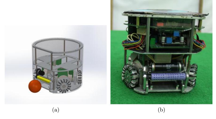
The robots are designed in Solidworks and extensive testing was done to validate the design using softwares like Ansys and Adams.
The robot chassis is manufactured with Aluminium 6061 to ensure strength of the robot. All the electrical components are organized in a housing compartment which ensures safety and accessiblity inside the robot. Table 1 summarizes hardware configuration of our bot.
Table 1. Robot Hardware
| Dimensions | Dia: 179mm , Height: 149mm |
|---|---|
| Driving motors | Maxon EC-45 Flat (45W) |
| Gear Type | Internal Spur |
| Gear Ratio | 1:3.3 |
| Wheel diameter | 50mm |
| Dribbling motor | Maxon EC-16 (16W) |
| Dribbling gear Ratio | 2:1 |
| Dribbling bar diameter Dia: 14mm | |
| Max. ball coverage | 19% |
| Sub-wheel Diameter | 10mm |
2.1 Locomotion System
The drive system is a four wheel omni-drive with back wheels inclined at 90 degrees and the front wheels inclined at 120 degrees to provide space for dribbler and kicker mechanism. The motor used for driving is Maxon EC45 (45W). Spur gears are used between wheels and motors with gear ratio of 1 : 3.3.
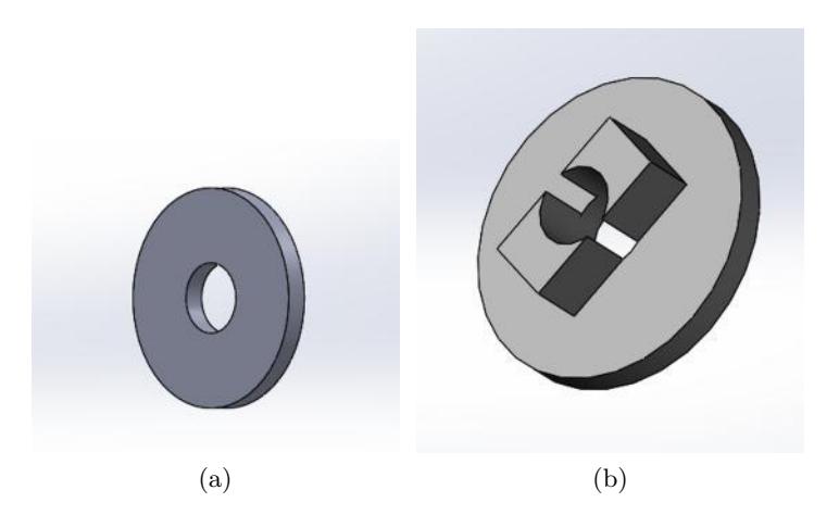
Wheels The number of sub-wheels in the omni wheel was optimised by analyzing the stress sub-wheels might experience during a collision. Another major change in our older robot is that the screw joining the wheel and the shaft used to loosen after few minutes of continuous motion of wheel. So we redesigned the washer and implemented a new square locker mechanism to prevent the loosening of screw as shown in Fig 2.
2.2 Dribbling Mechanism
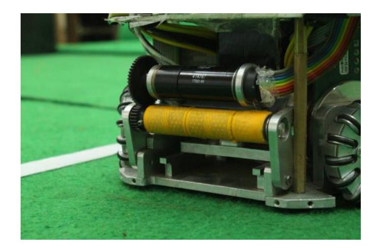
A dribbler bar made of Aluminium is used. Dribbler bar is directly driven by a brushless Maxon EC16 (16W) motor through two external spur gears with ratio of 2 : 1. To stop the ball from recoiling on impact, spring is used to dissipate its kinetic energy to ensure maximum ball handling. The back of the frame of dribbler mechanism is padded with compressible material (PVC foam) to absorb the ball impact. We tried out many materials for the grip of the dribbler and decided to use Polyurethane for this purpose which gave the best results. Our dribbler holds up to 19% of the ball which complies with the rule of SSL 2017.
2.3 Kicker System
Straight Kicker
The straight kicker is powered by two 250V 2200uF capacitor, which can be charged by a step-up converter upto 200V each but we have limited the voltage to 150V to limit the kicking speed to 6 m/s to comply with SSL rules.
- Solenoid The frame of solenoid is made of 6061-Aluminium alloy and is cylindrical in shape with an inner diameter of 11.4mm and an outer diameter of 12.5mm and its length is 44mm. After electromagnetic analysis using FEMM 4.2 and MATLAB, we found that 23 AWG wire gave the optimum results. So 23 AWG wire is wound with 680 turns.
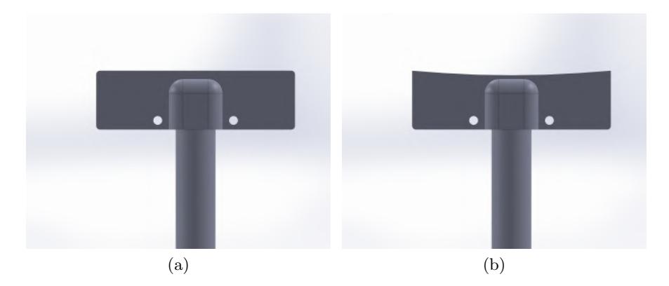
- Plunger Straight kicker consists of a custom made plunger with magnetic material (pure iron) of 45mm length and aluminium upon the remaining length.The diameter of plunger is 11mm. The dynamic analysis of a solenoid fed by constant current was done using MATLAB 2013a, FEMM 4.2 and ADAMS software. Another major design improvement is the design of the plunger. The plunger front part is curved to match the curve of the curvature of the ball so as to focus the energy to the ball as shown in Fig 4.
Chip Kicker
2 plunger designs were used. One with a thickness of 3.52 mm and length of 64mm (Plunger 1) and the other with a thickness of 2.67 mm and length of 70.75 mm (Plunger 2). Both plungers are 33.8 mm wide. Plunger 1 was observed to provide more energy(4.387 J) than Plunger 2(3.053 J), and hence was finally selected. Currently we are testing the prototypes.
3 Embedded System
Main controller board
The main circuit comprises of a STM32F407VG microcontroller which drives the 4 base motors, a dribbler motor and other peripherals. The four base motors used are ESCON 45W BLDC motors with line driver encoder feedback and ESCON 30W BLDC motor for dribbling. Each motor controller has its own microcontroller which has a inbuilt tuned PID controller. Inertial measurement unit (MPU 6050) has been used for controlling the bot orientation. The communication between the master computer and the bots is achieved using radio frequency modules (nRF24L01+). For accurate kicking, proximity sensor has been used to sense in the range of plunger action before kicking. The bot receives the wheel velocities, dribbling and kicking logics on the main circuit and communicates the kicker logic levels to the kicker circuit via trigger pins.
3.1 Main controller board
The main circuit comprises of a STM32F407VG microcontroller which drives the 4 base motors, a dribbler motor and other peripherals. The four base motors used are ESCON 45W BLDC motors with line driver encoder feedback and ESCON 30W BLDC motor for dribbling. Each motor controller has its own microcontroller which has a inbuilt tuned PID controller. Inertial measurement unit (MPU 6050) has been used for controlling the bot orientation. The communication between the master computer and the bots is achieved using radio frequency modules (nRF24L01+). For accurate kicking, proximity sensor has been used to sense in the range of plunger action before kicking. The bot receives the wheel velocities, dribbling and kicking logics on the main circuit and communicates the kicker logic levels to the kicker circuit via trigger pins.
3.2 Power Circuit
We have used one 5-cell, 2200 mAh, LiPo for power supply to power the whole robot. The battery operates at 18.5V. LM2596 buck converters regulates and supply constant 12V to the motor controller and 5V to the rest of the circuit with very low power dissipation.LM1117 voltage regulator has been used to obtain constant 3.3V. Continuous battery indicator is used which triggers an alarm if the voltage of any cell in the battery drops below 3.7 V.
3.3 Motor Controllers
ESCON 24/2 motor controller module is used to control the BLDC motors used in our robots. These controllers come with a dedicated microcontroller to drive one motor. The module has on chip auto-tuned PID controller for precise speed control of the BLDC motors with a 12-bit resolution for PWM signal. It can successfully control and drive the BLDC motor upto 10,000 rpm (although we drive the bots at 5,000 rpm as of now). The same motor controller has been used to control dribbler motors as well.
3.4 Communication Module
We have chosen an ultra-low power 2.4 Ghz RF module, nrf24L01+, for communication between the central computer and the robots.The module has a maximum of 32 bytes of dynamic payload length. The first byte is used for team-id, while the remaining 30 bytes are used to send 4 wheel velocities, dribbler velocity and kicking logic levels for 6 bots. The velocities respective to each bot are extracted at the bot side using bot id which is set manually using a 4-position DIP switch.
3.5 Kicker Board
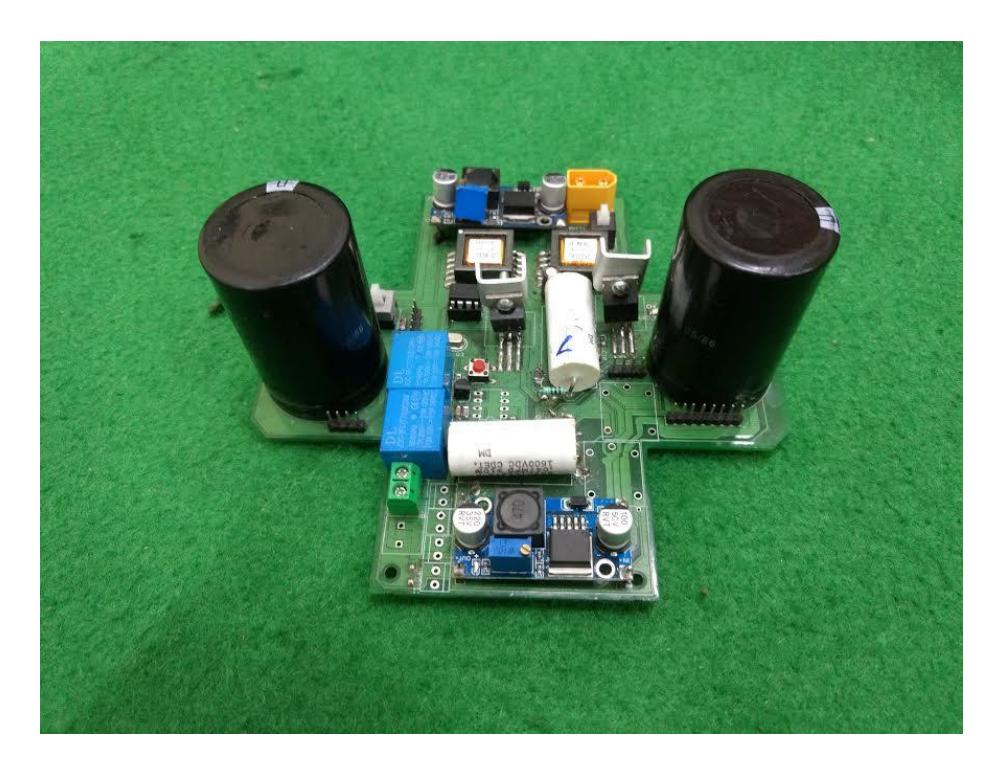
The kicker board constitutes of charging and discharging circuit. The kicker circuit has a dedicated ATMega 328 microcontroller. The kicker board receives external interrupt trigger and kicking level from the main circuit. Currently, our kick er supports 3 levels of kick namely - slow, medium and fast. The kicker can kick the ball at a maximum speed of 10m/s. The final fabricated Kicker circuit is shown in Fig 5.
Charging Circuit
The charging circuit is based on SMPS (Switch Mode Power Supply) and uses flyback converters. In this DC-to-DC step-up technique, switching is done at much higher frequencies. For switching, Power MOSFETs are used which are controlled by a PWM signal from Atmega with a frequency of 100 Khz. Charging time depends on the duty cycle of the PWM given to MOSFETs, which is optimized for fast charging. Basically the output (capacitors) of two flyback converters are conected in series. Both the capacitors (each of rating 2200uF, 250V) can charge upto 150V in 6-7 seconds. Feedback is also taken with the help of ADC peripheral of the microcontroller, to monitor the charging of capacitors.
Discharging Circuit
In the discharging circuit, the solenoid is connected in parallel to capacitors which is in series with relays for switching the discharging circuit. The relays are also electrically controlled with ATMega controller. Relays help in variable discharging. Also a high current flows while discharging, hence two relays are connected in parallel to avoid any burnout. To ensure a perfect kick two step detection is used to kick the ball i.e. first one through the camera on field and other through the break beam sensor incorporated on the bot, which helps to detect if the ball is in proper position for kicking.
4 Software
An overview of Skills, Tactics and Plays (STP) architecture developed on Robot Operating System is presented in subsection 1. Subsection 2 discusses path planning, namely the RRT algorithm used. It also discusses trajectory generation, velocity profiling, and trajectory tracking.
4.1 Software Architecture
Almost all teams building robot soccer software rely on some sort of multi layer framework, that separates lower level logic of the robot (path planning, locomotion) from the higher level logic (goalkeeping, passing, plays). We utilise the Skills, Tactics and Plays (STP) framework developed by the CMU team CM-Dragons.
Our previous STP implementation had several issues, such as:
– Single project, single executable: For testing a single part of the machinery, the whole project must be compiled and executed. No scope for unit testing.
– Deadlocks: Multithreading has been employed for parallelization. Even though semaphores have been used, deadlocks do occur and executable needs to be restarted.
We have rehauled our architecture and moved over to ROS(Robot Operating System). Earlier, our software was a single package written in C++. It has now been divided into several modules called ROS packages. Each ROS package can be individually downloaded and built, and provides several advantages over the previous implementation.
Modules:
- skills: Contains definitions of all skills.
- tactics: Contains definitions of all tactics, and definition of a tactic factory.
- plays: Contains definitions of all plays, and definition of a play factory.
- play exec: Describes node that executes a play and publishes tactic id and params to each ssl robot instance.
- ssl robot: Describes node that manages a single robot. Subscribes to belief state and play exec, publishes to comm data
- robot comm: Describes node that communicates with either grSim (the simulator) or the real robots, depending on the execution parameters. Subscribes to topic comm data and communicates over RF (real robots) or using protobuf (grSim).
- vision comm: Describes node that publishes vision info to the topic vision. Connects to either SSL Vision instance (real robots) or grSim instance (simulator) depending on execution parameters.
- kgpkubs launch: Contains .launch files and other scripts for launching all nodes on a machine.
- navigation: Contains definitions of planners and controllers used by Skills.
- belief state: Describes node that subscribes to vision and publishes BeliefState information on belief state. It includes state of robots and ball alongwith field parameters. The state comprises of position and velocity.
- ssl common: Contains miscellaneous libraries that are required by several modules, such as config files, network libraries, serializer/deserializer etc.
- ssl msgs: Contains all ROS message definitions required by other module. Communication on all topics must be through one of these message types.
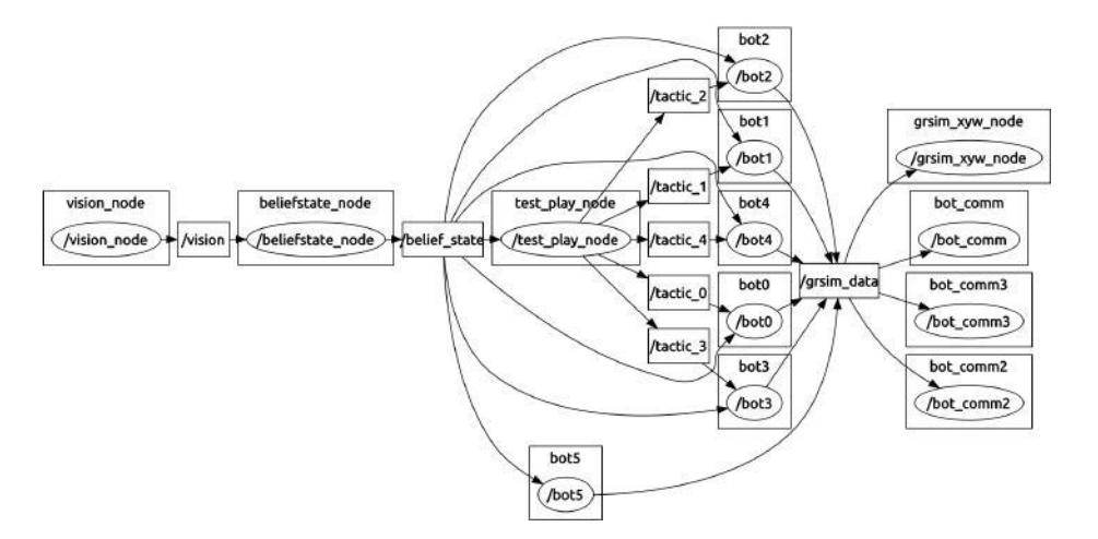
A sample of the flow of data between the ROS Nodes is shown in Fig 6. The image was taken using rqt graph in ROS.
4.2 Path Planning and Trajectory Control
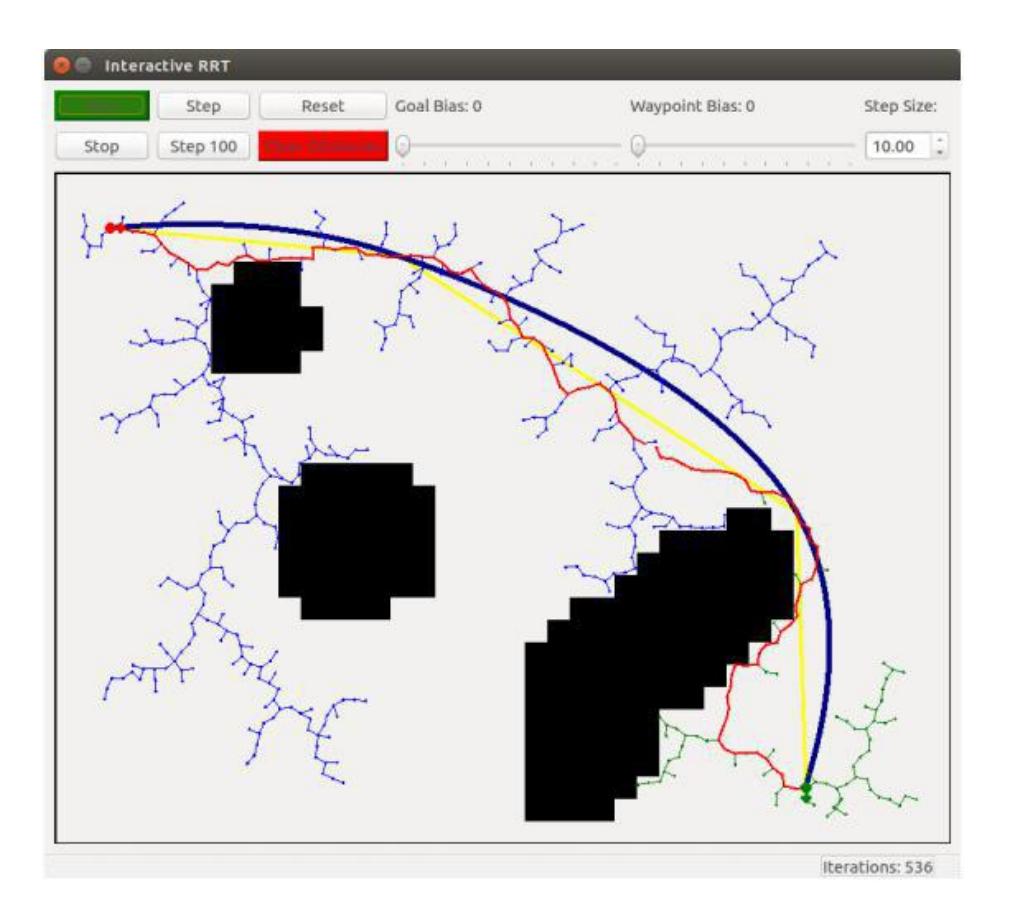
Almost all teams use Rapidly generated Random Trees (RRT) for finding obstacle free paths. In our case, we have adapted an RRT algorithm from team Robojackets of Georgia Tech University to tackle the challenges of obstacle avoidance, time predictability, and adherence to robot kinodynamics. It provides correct, robust trajectories within 3 send-and-receive cycles. The new features introduced by us include getting velocity values at each vertex, minimum time based neighbour search and cubic interpolation between planned points.
4.3 Trajectory Generation and Tracking
There exists a variety of motion planning approaches that use splines to represent trajectories. They all concentrate on several aspects of the problem but none accounts for all requirements that we consider important: a path that can be exactly followed by the robot (i.e., curvature continuity), explicit planning for velocities with consideration of kinodynamics, anytime capability, an optimization not prone to local optima, and treatment of unmapped obstacles.
Trajectory Generation We have developed a trajectory generation algorithm over the RRT planned path. In essence, we solve the cubic bezier (for both position and velocities) for the waypoints returned by the RRT generator. We then discretize the bezier by taking only a sample of points in each curve (currently set to 10), so that the result is again a set of time parameterized waypoints, however now much smoother. A sample result is shown in Fig 7.
Tracking We have simply used a PID tracker independently for each dimension of the configuration space: x, y, and theta. Using a PID tracker over a more complicated algorithm has several advantages:
- Modeling errors (of the linear kind) are inherently handled by PID control
- Oscillations and overshoots can be directly tuned through the Kd and Ki coefficients.
The disadvantage of this algorithm is that all calibration is manual, without the use of any modeling parameters. In the future, we may try to use trajectory linearization trackers which are claimed to perform better.
4.4 SSL Vision
As per increased requirements of ssl vision we made a decision to use a new camera for vision. The camera we used is Basler Aca2000 165uc which is a USB3.0 camera based on USB3 Vision standard. Being USB3.0 camera they provide better bandwidth and hence higher quality images at higher frame-rates. For access to full range of functions Pylon5.0 SDK has been used for integration of cameras with ssl vision which is provided by Basler for their cameras. The AOI, frame-rate, gain and other parameters of the camera can be set from the ssl-vision itself. Using the aforementioned ways we could achieve frame-rate of around 100fps which is more than the competition frame-rate. We look forward to merge this into the main ssl-vision in near future for the community to benefit from it.
4.5 Pass-Receive Tactic
Pass-Recieve Tactic have been implemented with a probabilistic method to determine the the recieving bot ID and the position of pass. Let Pa and Pb denote the prbabilties of receiving and shooting the pass respectively, then Pa and Pb will depend on the following parameters respectively.
- pa1 = Based on opponent who can intercept the pass i.e. a function of time taken by opponent bot to block the ball and time taken by ball to reach the position.
- pa2 = probability of receiving based on the length of the pass (Gaussain distribution)
- pb1 = Probability of shot reaching faster than goal keeper based on time taken by ball to reach the one end of goal and the goalkeeper to reach the same
- pb2 = Wide enough theta to reach the goal
- pb3 = based on defenders who can intercept the pass
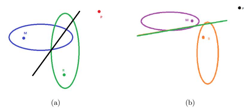
Line Ellipse model was used to find out the points for passing the ball when a marker is there. Considering ball's velocity greater than the marker's(M), we get the region where the ball can reach before the marker as a region outside an ellipse. Same goes for the receiver(R). Then we get the region where receiver and marker meet as a straight line considering their equal velocities. Passer was assumed to be (P).
Case 1: When both the ellipses and the line intersect as shown in Fig 8(a). In this case we get the sample points for checking the pass probability as the circumference points of the ellipse R on the region to the right of the line and outside the ellipse M.
Case 2: When the ellipses do not intersect but the line intersects with the ellipse of receiver as shown in Fig 8(b). In this case the sample space will be the points of the ellipse R which lie on the R side and those facing the goal side in case of goal attempt.
Case 3: When the ellipses do not intersect and the line does not intersect with the ellipse of receiver In this case all points on the ellipse can be taken as sample space.
5 Discussion and Future Works
As future work, it is imperative to explore more dynamics that affect the robot behavior. On the embedded side, we aim to incorporate variable discharging for controlling the speed with which ball is hit; develop fuzzy-PID controller based on encoder readings; integrate IMU for better state estimation. On the software side, we would improve upon the tracking algorithm and upgrade inter-tactic strategies such as pass-recieve.
Acknowledgements
The team also acknowledges the mentorship and guidance of our professors Prof. Jayanta Mukhopadhyay, Prof. Sudeshna Sarkar, Prof. Alok Kanti Deb and Prof. Dilip Kumar Pratihar. This research is supported by Sponsored Research and Industrial Consultancy(SRIC), IIT Kharagpur. We also thank our former team members who made all of this possible.
References
- Brett Browning, James Bruce, Michael Bowling, and Manuela Veloso. Stp: Skills, tactics, and plays for multi-robot control in adversarial environments. Proceedings of the Institution of Mechanical Engineers, Part I: Journal of Systems and Control Engineering, 219(1):33–52, 2005.
- Lindsey Langstaff Ryan Strat Robert Woodworth Justin Buchanan, Sean Csukas. Team description paper, robojackets gt, 2015.
- Tamas Kalmar-Nagy, Raffaello D'Andrea, and Pritam Ganguly. Near-optimal dynamic trajectory generation and control of an omnidirectional vehicle. Robotics and Autonomous Systems, 46(1):47–64, 2004.
- Michele Aicardi, Giuseppe Casalino, Antonio Bicchi, and Aldo Balestrino. Closed loop steering of unicycle like vehicles via lyapunov techniques. Robotics and Automation Magazine, IEEE, 2(1):27–35, 1995.
- Werner Dirk Jan Dierssen. Motion planning in a robot soccer system. A Master's Thesis, Language, Knowledge and Interaction Group Department of Computer Science University of Twente The Netherlands, 2003.
- Marko Lepetic, Gregor Klancar, Igor Skrjanc, Drago Matko, and Bostjan Potocnik. Time optimal path planning considering acceleration limits. Robotics and Autonomous Systems, 45(3):199–210, 2003.
- Christoph Sprunk and Boris Lau. Planning motion trajectories for mobile robots using splines. University of Freiburg, 2008.
- Gregor Klancar, Drago Matko, and Saso Blazic. Mobile robot control on a reference path. In Intelligent Control, 2005. Proceedings of the 2005 IEEE International Symposium on, Mediterrean Conference on Control and Automation, pages 1343– 1348. IEEE, 2005.
- Michael Bowling and Manuela Veloso. Motion control in dynamic multi-robot environments. In Computational Intelligence in Robotics and Automation, 1999. CIRA '99. Proceedings. 1999 IEEE International Symposium on, pages 168–173. IEEE, 1999.
- Alessandro De Luca, Giuseppe Oriolo, and Marilena Vendittelli. Control of wheeled mobile robots: An experimental overview. In Ramsete, pages 181–226. Springer, 2001.
- Oussama Khatib. Realtime obstacle avoidance for manipulators and mobile robots. The international journal of robotics research, 5(1):90–98, 1986.
- Brett Browning, James Bruce, Michael Bowling, and Manuela Veloso. STP: Skills, tactics and plays for multi-robot control in adversarial environments