MRL Extended Team Description 2017
Mohammad Sobhani, Mostafa Bagheri, Adel Hosseinikia, Hamed Shirazi, Sina Mosayebi, Saeid Esmaeelpourfard, Meisam Kassaeian Naeini, Aras Adhami-Mirhosseini
Islamic Azad University of Qazvin, Electrical Engineering and Computer Science Department, Mechatronics Research Lab, Qazvin, Iran
Abstract MRL Small Size Soccer team, with more than eight years of experience, is planning to participate in 2017 world competitions. In this paper, we present an overview of MRL small size hardware and software design. Having attained the third place in 2010, 2011 and 2013 competitions, second place in 2015 and first place in 2016, this year we enhanced reliability and achieved higher accuracy. We created new visualizer and logger software. Finally, by overcoming electronic and mechanical structure problems, we promoted the robots ability in performing more complicated tasks.
1 Introduction
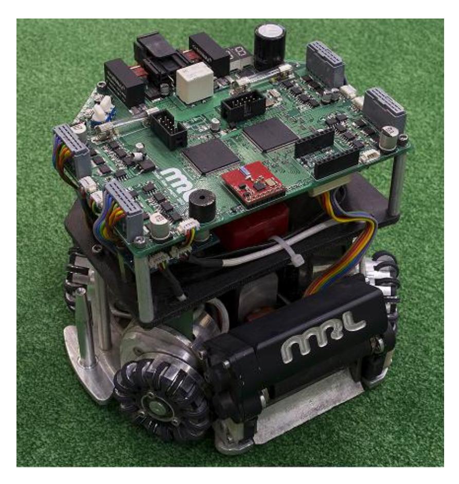
MRL team started working on small size robots from 2008. In 2016 Robocup, the team was qualified to be in semi-final round and achieved the first place. In the last competition in Germany MRL team ranked in the top 3 teams. In the upcoming competitions, the team goals is having more dynamic and intelligent behavior. In 2017 competitions the main structure of the robots is the same as last year, see [1] for details Figure 1 shows the MRL 2016 robots.
Some requirements to reach this target are achieved by redesigning the electrical and mechanical mechanisms. Moreover, simple learning and optimization approaches are employed in the way of more dynamic play. Evaluation by software tools, like new logger and visualizer.
This paper is organized as follows: First of all, the software contains visualizer and logger description 2. The Electrical design including ARM micro controller, and other accessories of robots onboard brain, is explained in section 3. Description of new wheels and mechanical structure, which modifies the capabilities of the robots dribbler system, is the subject of section 4.
2 Software
2.1 New open-source logger
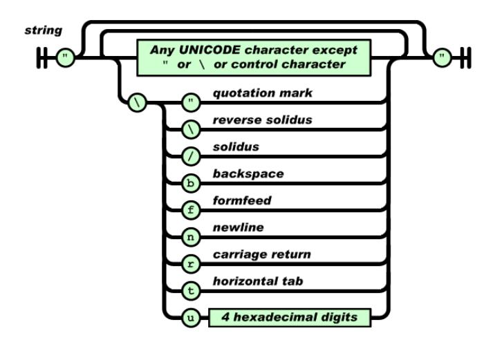
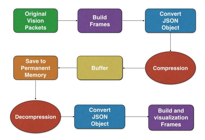
As we faced many problems including data not storing properly, size of our older log file was too large and filling the temporary memory, thats why it was decided to build a new logger. The new logger gets vision packet data from local network and transform them to a frame. Each frames was converted to JSON format as an string(each line is a frame) and buffer them to a data structure. The JSON list was compressed with Seven-Zip method and stored directly to permanent memory. In order to read a log file we converting data back to frames.
2.2 New open-source visualizer
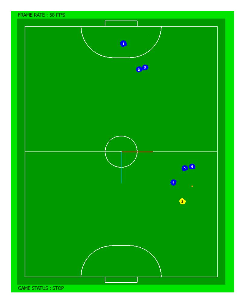
Due to simplification, showing details better and optimization, it was decided to build a new open source visualizer. The new visualizer is created based on Cartesian coordinate system that is designed with OpenGL graphical engine libraries. The logger and The visualizer are compatible, we can see log directly on the visualizer or we can simulate the log on the game field with robots. it is an open source software.
3 Electronics
3.1 Main Board
Over the past few years the electronic board of our robots have changed, many modules added on the board during changes that caused to decrease the performance of the robots , Instability and difficult repair. In order to fix this problem, we decided to combine the modules and main board as much as possible.
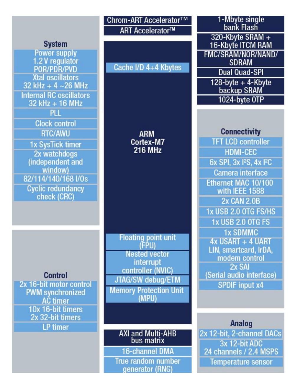
3.2 STM32F746ZG Micro-controller
Now the main board includes two chips, Altera's Cyclone FPGA connected to the ARM-type Micro-controller. We have decided to use STM32F746ZG with CORTEX-M7 core instead of both LPC2378 and the FPGA. The new STM32F746ZG Micro-controller is featured more than the LPC2378 Microcontroller. STM32F746ZG is operating up to 216MHz frequency but the old Micro-controller were operating up to 72MHz. [5]
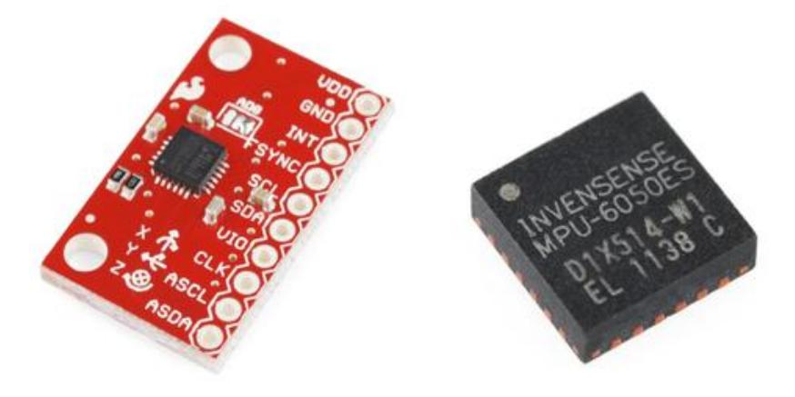
3.3 MPU-6050 module
We had some limits when we use just Vision and Encoder to control robots so we decided to use an accelerometer to gather more data and improve our robot control. Among the existing accelerometer, MPU-6050 module is a better choice because the MPU-6050 module is a 6-axis motion tracking sensor including a MEMS 3-axis gyroscope, a MEMS 3-axis accelerometer and a digital motion processor (DMP). MPU-6050 module allow the user to change the measurement in proportion to acceleration or angular velocity. The output data from the MPU-6050 will be use beside other controlling parts after kalman filtering in order to improve robot movement controls.[2]
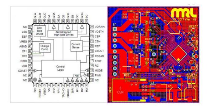
3.4 A3930 BLDC motor driver chip
as we mentioned, a new board were designed including IR sensor block and Spin back motor driver in order to integrate the robots electronic boards. Also in order to optimize Motor-driver block it was decided to use the A3930 BLDC motor driver chip, that makes the driver block smaller and a more integrated MOSFET driver circuitry in comparison with the last MOSFET driving method including the FPGA and LM5101 chip. The A3930 chip is capable to drive the 3-phase BLDC motor in a stand-alone mode , automatic and hardware current limit control.[6][7]
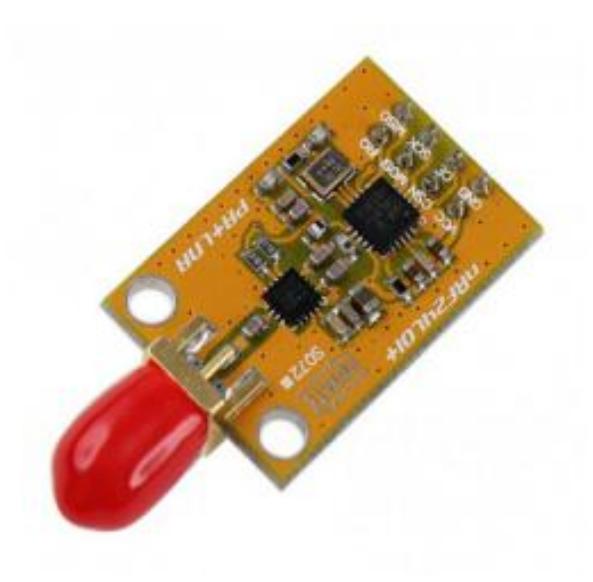
3.5 NRF24L01+ (with PA+LNA)
For having a stable high speed two-sided wireless data transition, two NRF modules are needed in robots. We decide to use a new NRF24L01+ module with PA(Power Amplifier) and LNA(Low Noise Amplifier) for sending and receiving data instead of the simple NRF24L01+ because of instability and data lost in sending and receiving data. [4]
4 Mechanical Design and construction
Typically, the main portions of mechanical structure of a small size robot, include 4 wheels, two kickers, a dribbler and the motion transformer system. Regarding the league rules, diameter of the robot is 179mm and the height is 140mm. The spin back system conceals 20% of the ball diameter in the maximum situation.
Due to some drawbacks in the previous proposed design, we have decided to improve both the mechanical design and the construction materials. Main changes in the mechanical structure of the robot are described in the following paragraphs. The other parts are the same as 2014 robot described in [1].
4.1 Wheel system
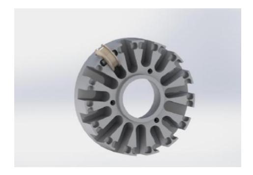
We use wheels for movement, there is grooves on the wheels. Pin and pulley placing in grooves You can see the assembly method on Figure 9.
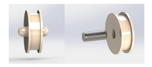
The problem of pin and pulley was assembly and material. In order to fix this problem we changed pulley material and remove pin. You can see the pin and pulley before and after changes in Figure 10 . The material of old pulley was Aluminum, Due tothe pulley have bean bended by collision, we change the material to a plastic-like matter with ABS behavioral features.
4.2 Dribbling system
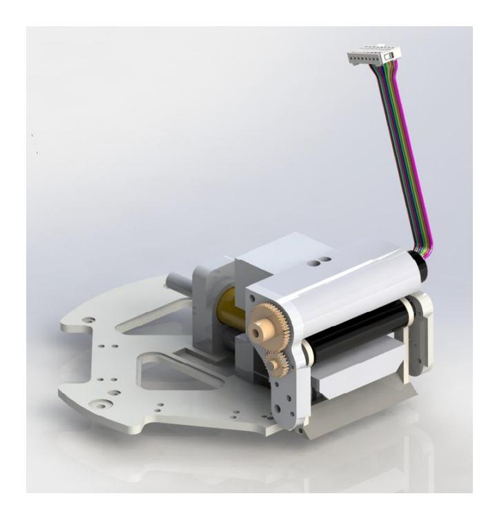
Dribbling system is a mechanism to improve the capability of ball handling. As it is shown in Figure 11, dribbler is a steel shaft covered with a rubber and connected to high speed brushless motor shaft, Maxon EC16 Brushless. Since the spin back motor is in the front side of the robot, it is exposed to the strikes caused by the collision with the ball or other robots. To solve this problem, we took the spin back motors position a little back and designed a shield for it. To improve the capability of spin back to control the ball, we made a construction in which the amount damping is controlled.
References
- Ganjali Poudeh, A., Beik Mohammadi, H., Hosseinikia, A., Esmaeelpourfard, S., Adhami-Mirhossein, A.: MRL Extended Team Description 2014. Proceedings of the 17th International RoboCup Symposium, Jao Pesoa, Brazil, (2014).
- InvenSense Inc: MPU-6000 and MPU-6050 Product Specification Revision 3.4, 2013.
- Utilizing a Vishay IrDA Transceiver for Remote Control. Application Note by Vishay Semiconductors, Doc. No. 82606, (2014).
- Nordic Semiconductor: nRF24L01+ Product Specification v1.0,(2008)
- STmicroelectronics: STM32F745xx, STM32F746xx Datasheet, December(2015)
- LLC Allegro MicroSystems: A3930 and A3931, Automotive Three Phase BLDC Controller and MOSFET Driver, A3930 and A3931 Datasheet
- LLC Allegro MicroSystems. A3930 and A3931 Automotive 3-Phase BLDC Controller and MOSFET Driver, A3930-1 Demo board Schematic/Layout