NEUIslanders 2017 Team Description Paper
Prof. Dr. Rahib H. Abiyev, Assist. Prof. Dr. Irfan GUNSEL, Nurullah AKKAYA, Mustafa ARICI, Ahmet CAGMAN, Seyhan HUSEYIN, Can MUSAOGULLARI, Ali TURK, Gorkem SAY, Berk YILMAZ, Berkant KAPTAN, Ersin AYTAC
Department of Computer Engineering; Department of Electrical and Electronic Engineering; Department of Mechanical Engineering; Near East University, Lefkosa, TRNC
Abstract This paper presents the detailed description of 3rd generation of NEUIslanders robotics team of small size league in RoboCup 2017 which is going to be held in Nagoya, Japan. The major improvements of the mechanical, electronics and software design are described. The robots are designed under the RoboCup 2016 rules.
1 Introduction
NEUIslanders is an interdisciplinary team of undergraduate and graduate students at Near East University. The team has been attending to RoboCup events since 2012, and currently seeking qualification for RoboCup 2017. Since last year, NEUIslanders team focuses on improvement of more efficient energy use, high accuracy passing and shooting and more efficient path finding. The paper is going to outline the progress in implementation of the current model of robots.
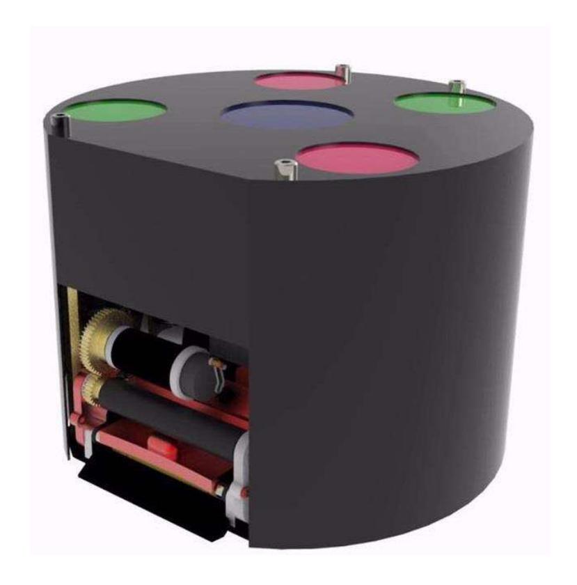
NEUIslanders robots consists of three major component, which are; the robot mechanical parts, electronic control board, and control software. Changed mechanical parts and the improved wheel design are going to be explained in detail and illustrated. Dribbler motor driver and more accurated kicking electronics is described. Also the implementation of fuzzy logic in software is outlined.
Robot Specifications
| NEUIslanders Robot Specifications | |
|---|---|
| Dimensions | Ø178x145mm |
| Weight | 3150gr |
| Driving Motors | Maxon EC-45 Flat 30Watt with 2048ppr Encoder |
| Driving Gear Ratio | 72:20 |
| Dribbler Motor | Maxon EC-16 15Watt |
| Dribbler Gear Ratio | 24:48 |
| Kick Speed | Up to 8m/s (electronically limited) |
| Pass Accuracy | %80 |
| Communication | XBEE 1mW |
2 Mechanical Design
2.1 Omni-Wheel Improvements
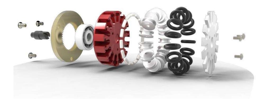
After a heavy use of the rollers for the last two and a half years we observe that the rollers cross section turns from V shaped to U shaped, which creates problems of the omni directional movement also because of the wear off some of the o-rings started to tear down during the training sessions in our laboratory. For comperasion purposes we bought 50-70-90 durometer o-rings and keep on testing them. In next TDP we will publish the results of different durometer o-rings effect on the performance.
Also to improve the movement we decided to change the robot ball bearings from stainless steel bearings to ceramic hybrid bearings. Because of the carpet hairs coming into the bearings and causing the ball bearings not working properly we decided to renew all the ball bearings on our robots with hybrid ceramic bearings. Because of the hybrid ceramic ball bearings we observe %4 energy efficiency and more smoother movement.
2.2 Electronic Board & Battery Holder
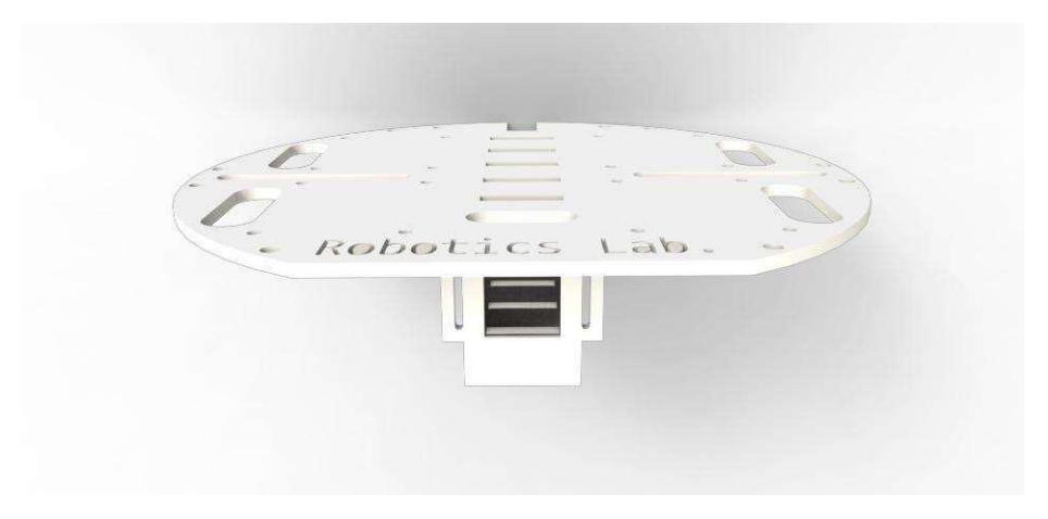
In last generation of our robots we have been observing that accelerations and decelerations over 4.5m/s² robots tend to tip over. To solve this problem we have been thinking of a way to get the center of gravity lower. Since the lower part of the robot is cramped with motors, kicker, dribbler, and chip kicker we decided to change our batteries with much more smaller in dimensions. Since the battery is %7.15 of the total weight of a robot and moving the battery to 6cm lower postion will solve the problem.
In our design we use a middle layer of sheet plastic or aluminium for the past years to mount the electronic speed controllers, capacitor, and battery. Since the additive manufacturing technologies are becoming more common and as NEURobotics Laboratory we have a sister laboratory called NEU3D Laboratories the new designed electronic board and battery holder is 3D printed with a FDM printer which has a housing for battery in between the robot motors just over the kicking mechanism with 1.5 millimeters of clearence.
3 Electronic Design
After last year's circuit stability, working properly and circuit efficiency, the electronic team have focused on improvement of chip kick and the chip kick stability, main kicker stability, autokick stability and dribbler stability. To achieve these improvements, new designs have been adapted to circuit design and system. Also the section of voltage booster topology has been changed. The new topology will be described and new circuit schematic will be shown in this section. The new circuit has been simulated in MATLAB Simulink and new pcbs have been design in AUTODESK Eagle (former cadsoft eagle) pcb design.
3.1 Improvements
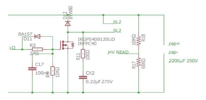
One of the most important improvements for this year is the implemention of chip kick. Because of some problems the chip kick was out of order last year. All of the chip kick inductances have been equalized to 540 µH. To apply same force to ball for all robots, this process has been achieved. Turn numbers of solenoids have been decreased to reach this value. Then, the chip kick has been connected to pcb board. The schematic design shown in figure 4.
The pwm signal comes through the LO. R3 resistor has been used for limiting to gate current. D11 diode has been used to discharge the gate capacitances bypassing the gate resistor. So the turn off time of IGBT will be reduced. R4 resistor has used for fault triggering of the IGBT. The different pwm values have used for different forces. Both main kicker and chip kicker use the same 2200 µF 250 V capacitor.
Another improvement has been achieved for main kicker stability. The solenoids turn numbers have been equalized to apply same kicking force. The new solenoid values are 1413 µH. By achieving these equalization process, all of our robots can kick the ball to the absolute same point. That achievement is going to open the way to pass more accurately in between our robots. The kicking force has set by pwm value.
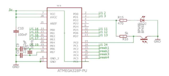
In our laboratory, the constant light level has provided. But in competitions, the light level can be change during day. The auto kick has been stabilized by setting some values. BPW85 photo-transistor and red led have been used for auto kick section. R16 resistor has changed to 5K ohm after light trouble. The auto kick schematic shown in figure 5.
Dribbling section of the circuit has another improvement also. Because of the electronic speed controller of the dribbler motor wasn't responding as fast enough as expected, we have started to design of new dribbler motor driver.
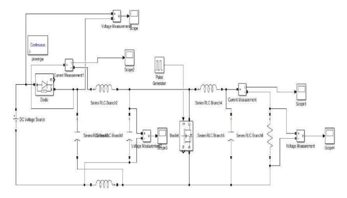
The power loss and efficiency are the most important parameters of this technology. Especially in electronic design, these parameters have to be minimum and maximum respectively. The new dc to dc converter topology that called z-source has been designed this year. The z-source topology offers us to unique impedance connection to couple the converter to power source. This topology also can be applied to dc-ac, acdc, ac-ac, dc-dc conversions. Z source dc-dc converter has shown in figure 6.
The simulation of z-source circuit has been designed in MATLAB Simulink. X shaped inductors and capacitors provide impedance source coupling. When the mosfet turned off, the battery start to charge z source capacitors and inductors discharge their energy to the load. In mode 2 the mosfet turns on. The z-source capacitors discharge and inductor starts to store energy back. Output inductor and capacitor have been used for filter. All of these simulation tests and circuit designs will be published open source.
After all of these improvements, the chip kick, main kicker, dribbler, auto kick and voltage boost section have became more stable and relible.
4 Software Design
Past year the software team focused on the following areas;
- Path Finding
- Chip Kick
- Fuzzy Logic Control
4.1 Design of Path Finding Procedure
For the past couple of years our software relied on potential fields for path finding. One limitation of potential field path finding is that it is slow, in order to overcome that problem we've implemented a variation of potential field path finding, instead of calculating whole path from A to B, we calculate the total potential force acting on the robot at each tick of the AI and then combine that with out intended travel velocity. This scheme is fast and works when robots are moving slowly, as the robots/obstacles gets faster this method becomes unstable. This caused us Yellow cards in both Robocup Germany and European Open. In order to overcome that this year we've switched to RRT based path finding.
One of more used algorithm that can be used for path finding purpose is fast dynamic environment is a Rapidly Exploring Random Tree (RRT) algorithm [12]. RRT algorithm is designed for efficiency searching for a path from the start state to the goal state by expanding the search tree, as follows,
- Initialize the tree with the starting point as root
- Pick a random point within the valid parameter space
- Search the one vertex in the tree which is nearest to the random point chosen in 2
- Move a certain distance from this vertex in the direction of the chosen point and create there a new leaf
- Loop over step 2. to 4. while the break condition is not satisfied
The key idea of RRT is to bias the exploration towards unexplored portions of the space by sampling points in the state space, and pulling the search tree toward them. The algorithm proceeds by growing a single tree from the initial configuration until one of its branches encounters the goal state. Algorithm attempts to extend the RRT by adding a new vertex that is biased by a randomly-selected state. The inputs for RRT are map of the environment, start and goal position, RRT tree and the amount it is expanded at each step. During the run of the algorithm, at the first stage, "chooseTarget" determines where to explore the map by randomly selecting a point on the map giving bias towards the goal, with probability pGoal, that expands towards the goal minimizing the objective function of distance. Here, using random number generator, uniformly points are generated to choose a target. Then algorithms determine nearest node using "nearest" procedure. If the distance between the node and target position is less than the distance between generated point and target position then the generated point is selected as new node where tree will be explored. In each iteration when the new node is selected, the distance between this nearest point and goal position is tested. If this distance is less than the required small value epsilon then the tree is returned as result of RRT algorithm. In other case tree is extended and explored. During extension of the tree the presence of obstacles are tested. In the case of presence of obstacles the tree is not extended toward to that direction. In other case the selected tree will be extended towards the chosen target and RRT algorithm will be iterated until goal position is reached.
function RRT-Plan (world, start, goal, epsilon, p-
goal, tree)
target ← chooseTarget(world, pGoal, goal)
      nearest ← nearest(tree, target)
      if( distance(nearest,goal) < epsilon
       ) return tree
      else
       explored ← explore(world, nearest,
target, epsilon)
       if (explored != nil )
        addNode(tree,explored
        )
       RRT-Plan(world, start, goal, epsilon, p-goal,
tree)
    function chooseTarget(world, pGoal, goal) p
      ← UniformRandom in [0.0 .. 1.0]
      if 0 < p < pGoal
       return goal;
      else
       return randomState(world)
    function nearest(tree,target)
      point ← first(tree)
      for each node in rest(tree)
       if distance(node, target) < distance(point,
target)
        point ← node
      return point
    function explore(world, u, v, epsilon)
      explored ← extend(u, v, epsilon)
      if checkCollision(world, explored) = false
       then return explored
      else
       return nil
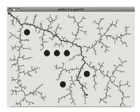
The RRT algorithm is extremely simple and cheap to calculate but it is not optimal. A path will be computed quickly but it is not guaranteed to be the cheapest and will result a different path for every search. Fig.7 depicts the result of RRT algorithm. As shown RRT algorithm finds many paths on the map of environment in shortest time, then selects the path that can get the goal.
In robot navigation the determination of shortest path in a short time is very important. As shown in Fig.7 the path returned by the RRT algorithm is not optimal. It contains many zig zags and unnecessary edges. In order to deal with this problem, we use a simple path smoothing algorithm that is not too time consuming. In the paper the quick path smoothing described in is applied to optimize the selected path on the map.
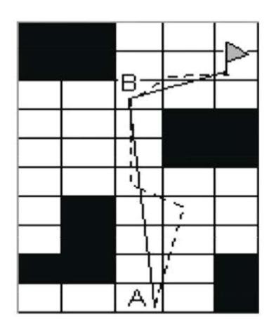
Smooth-path is a recursive algorithm that will keep dropping nodes that are reachable from the given node. Fig.8 demonstrate path smoothing scene. Given two nodes that are reachable A and B. Assume that A is start point of the path Fig.8. This algorithm removes any nodes between A and B since we can go from A to B directly without going through all the nodes in between.
Path smoothing algorithm is given in Fig.8. Smooth-path starts with first node in the path, it then calls drop-while-walkable function which finds a node that is farthest from the first node that can be reachable without collision. The function adds this node to the path and does the same operations for this node, this process is repeated until there are no more nodes on the path in which case the function returns. In Fig.8 a dashed line depicts the original path that robot try to get goal position, solid line demonstrates the optimal smoothed path. In the result of smoothing the path is optimized. The use of path smoothing procedure with RRT-Plan allows to optimize the path of the robot.
function smooth-path (isWalkable, path, curr-node,
path-rest)
      if(isEmpty(rest) == false)
       path-rest = drop-while-
walkable(fn(isWalkable,curr-node,%),path-
       rest) x = first(path-rest)
       xs = rest(path-rest)
       smooth-path(isWalkable, addNode(path-
rest,curr-node), x, xs))
      else
       return addNode(path-rest,curr-node)
    function drop-while-walkable (pred, path, curr-node)
      if(isEmpty(path) == false && pred(first(path)) ==
true)
       drop-while-walkable(pred, rest(path),
      first(path)) else
       return addNode(curr-node,s)
4.2 Fuzzy Logic implementation of behaviour tree nodes
Our software architecture relies heavily on behavior trees. [13] [14] Behavior trees combines a number of AI techniques such as Hierarchical State Machines, Scheduling, Planning, and Action Execution. Their strength comes from the fact that it is very easy to see logic, they are fast to execute and easy to maintain. which makes them suitable for representing complex and parallel behaviors.
Behavior trees allow us to piece together reusable blocks of code which can be as simple as looking up a variable in game state to sending a motor command, then the behavior tree is used to control the flow and execution of these blocks of code.
As its name implies a behavior tree is a tree structure, made up of three types of nodes, action, decorator and composite. Composite and decorator nodes are used to control the flow within the three and action nodes are where we execute code (such as calculating a new path or sending a velocity command to a robot) they return success or failure and their return value is then used to decide where to navigate next in the tree. Figure 9 shows one of our lower level behaviors move-to which is responsible for providing move function for other behaviors.
Selector and sequence nodes (composites) are workhorse internal nodes. Selector node will try to execute its first child, if it returns success it will also return success if it fails it will try executing its next child until one of its children returns success or it runs out of children at which point it will return failure. This property allows us to choose which behavior to run next.
On the other hand, a sequence represents a series of behaviors that we need to accomplish. A sequence will try to execute all its children from left to right, if all of its children succeeds sequence will also succeed, if one of its children fails sequence will stop and return failure.
Finally, decorators are nodes with a single child, it modifies the behavior of the branch in some way such as creating loops in the tree or modifying the return value of its children.
Robot soccer is operating in unpredictable, uncertain and dynamic environments. Making decision against desired outcome needs the accurate evaluation of the environment. In such cases, fuzzy sets are powerful tools for the representation of uncertain and vague data. By applying approximate reasoning, a fuzzy inference system makes a decision.
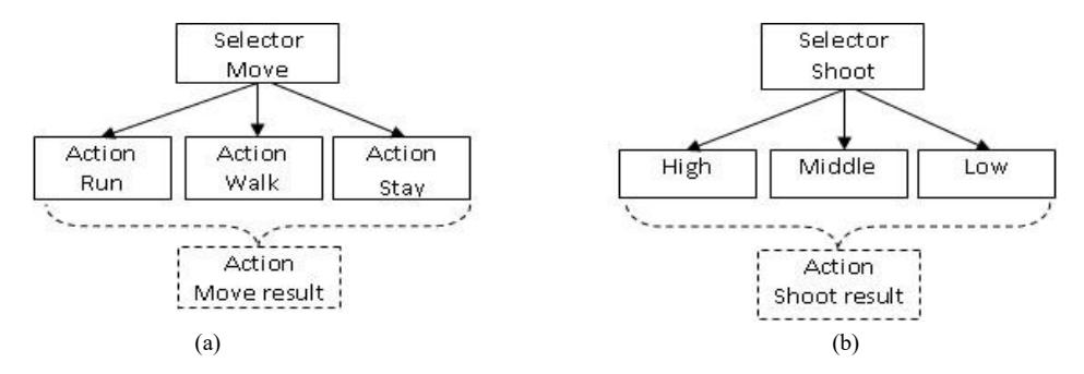
In the robot soccer control, fuzzy logic includes a range of degrees for decisions. These degrees are denoted as a membership function. Here integration of fuzzy inference and BT is proposed for the selector behavior. Membership functions are defined for the child of the selector. For example, the deterministic Move behavior can be implemented using Run, Walk and Turn (Fig.10(a)). Implementation one of these operations depends on a set of conditions. Depending on the value of input data obtained from the environment the membership degree is determined for the each of the decision. The selection of each block is determined by the condition defined in the body of BT. The fragment of the rule is given below.
If ball is near and ball speed is low then execute sequence walk If ball is far away and ball speed is high then execute sequence run If ball is far away and ball speed is very low then execute sequence stay
The input and output of rule base are determined according to the technical and performance characteristics of middle size soccer robots. Using those characteristics, on the base of experimental data and expert knowledge, the fuzzy rule bases (RB) are designed for given processes. The implementation of BT is carried out on the base of formulas given below. The output of the fuzzy BT will have continues value. For example in the deterministic case for the tree given in figure 10(a) the output of tree is one of the children- Run, Walk or Stay. As known these classes are derived in the result of classification of the speed of the robot soccer. In deterministic case, each of these classes has certain crisp value. In fuzzy case, there is no crisp restriction between the bound of these values. The value of these classes are the fuzzy interval, they will not have so strict ground. In the result of fuzzy inference, the calculated final speed of the robot soccer may not belong to the deterministic Run, Walk or Stay. It may have continues value that will belong to the one of the value between zero and a maximum speed of the robot.
Another BT is about Shoot Ball fuzzy selector node that could be implemented in three different ways are given in Fig.10(b).
Using the rule base the output of the BT is determined. The determination of the output is performed using a fuzzy inference engine. The inference engine in BT is implemented using max-min composition. The current values of input coming signals after fuzzification are entered to the rule base, where membership degree of each input signal to current fuzzy term in RB is calculated.
Inference of fuzzy system is performed by the following formula
$$\tilde{X1}, \tilde{X2} \to \tilde{Y}$$
where $\widetilde{Y}$ is a speed of the robot characterising one of the output Run, Walk, Stay, $X\widetilde{1}, X\widetilde{2}$ are distance to the ball and speed of the ball respectively. After defining the membership degrees of the input signals for each active rules in rule base the fuzzy logic inference is performed using max-min composition of Zade.
$$\mu(y) = \max_{x1,x2} \min{\mu_{X1}(x1), \mu_{X2}(x2), \mu_{R}(x1,x2,y)}$$
Using the "Centre of average" method the defuzzification process of fuzzy output signal is performed.
References
- Rahib H. Abiyev, Nurullah Akkaya, Ersin Aytac. Navigation of Mobile Robot in Dynamic Environment. IEEE CSAE 2012 Conference, China
- Rahib H. Abiyev, Nurullah Akkaya, Ersin Aytac, Mustafa Arici, Muhlis Bayezit. NEUIslanders Team Description Paper 2012, Robocup SSL, MexicoCity, Mexico
- Rahib H. Abiyev, Senol Bektas, Nurullah Akkaya, Ersin Aytac. Behavior Tree Based Control of Holonomic Robots. International Journal of Robotics and Automation. WSEAS Conference 2013, Limasol, Cyprus
- Rahib H. Abiyev, Nurullah Akkaya, Ersin Aytac. Control of Soccer Robots Using Behaviour Trees. ASCC 2013
- Rahib H. Abiyev, Senol Bektas, Nurullah Akkaya, Ersin Aytac. Behavior Trees Based Decision Making for Soccer Robots. Recent Advances in Mathematical Methods, Intelligent Systems and Materials 2013
- Rahib H. Abiyev, Nurullah Akkaya, Ersin Aytac, Dogan Ibrahim. Behavior Tree Based Control For Efficient Navigation Of Holonomic Robots. International Journal of Robotics and Automation
- Ali Erdinc Koroglu, Rahib Abiyev, Nurullah Akkaya, Ersin Aytac, Mustafa Arici, Kamil Dimililer. NEUIslanders Team Description Paper 2013, Robocup SSL, Eindhoven, Netherlands
- Rahib H. Abiyev, Nurullah Akkaya, Ersin Aytac, Irfan Gunsel, Ahmet Cagman Improved Path-Finding Algorithm for Robot Soccer. International Conference on Control, Robotics and Informatics. Hong Kong 2014
- Rahib Abiyev, Nurullah Akkaya, Ersin Aytac, Gorkem Say, Fatih Emrem, Mustafa Arici. Team Description Paper 2014, Robocup SSL, João Pessoa, Brasil
- Prof. Dr. Rahib H. Abiyev, Assist. Prof. Dr. Irfan Gunsel, Nurullah Akkaya, Murat Arslan, Mustafa Arici, Ahmet Cagman, Seyhan Huseyin, Fatih Emrem, Gorkem Say, Ersin Aytac. Team Description Paper 2015, Robocup SSL, Hefei, China
- Prof. Dr. Rahib H. Abiyev, Assist. Prof. Dr. Irfan Gunsel, Nurullah Akkaya, Murat Arslan, Mustafa Arici, Ahmet Cagman, Seyhan Huseyin, Fatih Emrem, Berk Yilmaz, Huseyin I. Ercen, Gorkem Say, Ersin Aytac. Team Description Paper 2016, Robocup SSL, Leipzig, Germany
- S. M. LaValle. Rapidly-exploring random trees: A new tool for path planning. Technical Report 11, Computer Science Dept., Iowa State University, 1998.
- Alex J. Champandard. Getting started with decision making and control systems, ai game programming wisdom 4, section 3.4, pp. 257–264, 2008.
- Chong-U Lim. An a.i. player for defcon: An evolutionary approach using behavior trees, 2009.