OP-AmP 2017 Team Discription Paper
Takamichi Yoshimoto, Takato Horii, Shoma Mizutani, Yasuyuki Iwauchi, Yutaka Yamada, Kousei Baba, Shota Zenji
Asagami Works, Osaka, Japan
http://www.asagami-works.pro/opamp/
Abstract This paper introduces the explanation of hardware and software of a RoboCup small size team "OP-AmP". A unique point of our robots is Multi angle kicking device, which employs Geneva drive for a variable angle mechanism. This device enables robots to kick a ball as "no-look pass" and our software to extend a variety of strategies during games. A dribble roller of our robot contributes kicking accuracy to the kicking device. The roller can automatically center a ball on the kicking device even though the ball contacts anywhere on the roller. In the software, we developed a detection system of a chip kicking ball to improve accuracy of passing plays. Additionally, we employed velocity-bounding proxy-based sliding mode controller as a high-level controller to realize stable control and the Bayesian optimization scheme to optimize parameters of the controller.
1 Introduction
OP-AmP[1] is a team of RoboCup SSL established in 2011, and members are interested people who graduated RoboCup team "KIKS". We won third place in RoboCup JapanOpen 2014 and 2015, and won second place in RoboCup JapanOpen 2016. Further, we received the Special Award of the Robotics Society Japan in 2013 owing to our unique mechanism of a kick device.
This paper explains a system of our robot and software. We extended our robot to third generation based on 2013 models. The robot has two unique mechanisms, which increase a number of strategies during games. One is a kicking device with a variable angle mechanism and the other is a dribble device that can automatically bring a ball toward the center of a dribbling roller. These devices are described in detail in section 2. In the following section 3, we describe circuit boards of our robot. The feature of the circuit is that current vector control is applied to motor control. This control system improves responsiveness and controllability in a low-level controller (i.e., motor control). On the software side, we explain an effective trajectory for approaching a ball and a detection method of a floating ball. In addition, we describe a method to apply velocity-bounding proxy-based sliding mode controller (VBPSMC) as a high-level controller and an optimization scheme of its control parameters. These systems are described in section 4.
2 Hardware
Our robot was developed targeting RoboCup 2017. The CAD image of the robot is shown in Fig.1 and improvements from 2016 are shown in Table 1. The main improvements are development of Multi angle kicking device with Geneva drive and the dribbling device with an auto centering roller. Most conventional robots make a game using straight kick and chip kick. But, a more advanced strategy like a human game requires diversification of kicking technique. These improvements made it possible to diagonal kick. And it can be operated like the no-look pass.
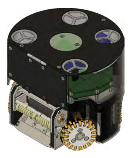
Table 1: Comparison of specifications
| Model | 2013 - 2016 | 2017 |
|---|---|---|
| Weight (without battery) | 2.32 kg | 2.20 kg |
| Main Material | Aluminum alloy(A2017), POM | |
| Driving motor | maxon EC45 flat (30W) | |
| Gear ratio | 3.6 : 1 | |
| Wheels | Double layered omni wheels (small wheels 18pcs x 2) | |
| Kicking device | Multi angle kicking device with servo motor x1 | Multi angle kicking device with Geneva drive x1 |
| Chip kicking device x1 | Chip kicking device x1 | |
| Dribbling roller | Urethane roller | formed by 3D printed molds |
2.1 Double layered omni wheel
The robot is equipped with a double layered omni wheel to improve driving efficiency and grip performance. Small wheels (18pcs x 2) bring the omni wheel closer to the circle, reducing the loss due to vertical vibration. And the urethane rubber (width = 3mm) with high strength and grip performance is used as a small wheel. The basic configuration of small wheels is the same as KIKS 2013[2].
2.2 Multi angle kicking device
We made the prototype of multi angle mechanism in 2012. From 2013, it was operated on the strategy system. And this year, we made improvements by feedbacking problems discovered in actual games.
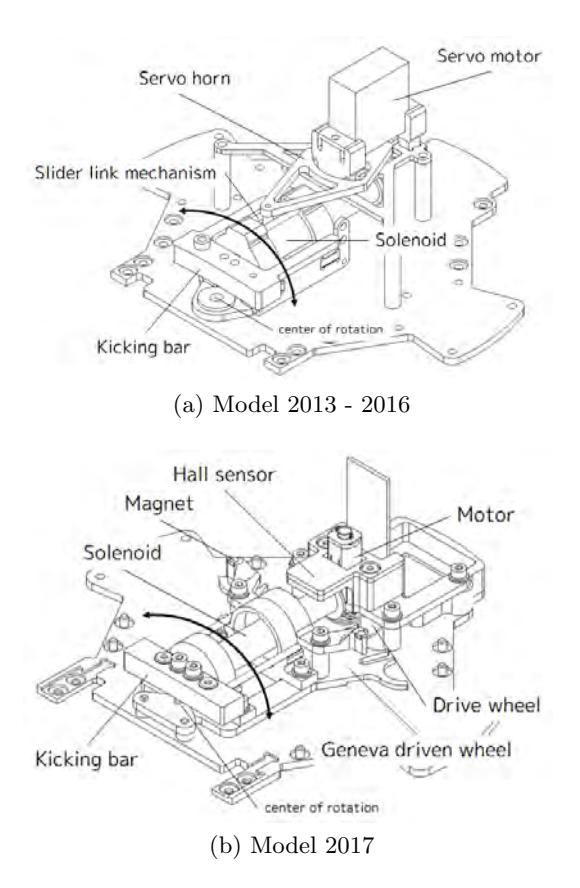
In the model from 2013 to 2016, the servo motor was used to rotate the kicking device. Fig. 2 (a) shows the structure of the kicking device from 2013 to 2016. In this system, the servo is not loaded by a kick directly because the servo motor and the kicking device are connected by the slider link mechanism parallel to the kick direction. However, there was a problem that the straight kick moves a little to the left and right due to the clearance of the slider. Also, in actual use cases, it was used in the defined set play, and a changing to arbitrary angles was not a big advantage.
Therefore, in the 2017 model, it changed to a method of rotating the kicking device using the Geneva drive. Fig. 2 (b) shows the structure of the kicking device in 2017. The Geneva drive is a gear mechanism that converts continuous rotation to intermittent rotation. The Geneva driven wheel rotates by a certain angle according to the intermittent rotation. In this model, the kicking device is placed on the driven wheel. Therefore, although the kicking device rotates only at every certain angle, it can be positioned with high accuracy and durability.
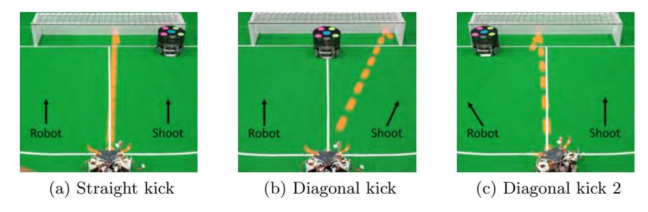
The Fig.3 shows an experimental result of Multi angle kicking device. It can kick in a direction different from the robot. In addition, it can kick straight as before in the same direction of the robot. This Multi angle kicking device is a big advantage against the strategy system that estimates only depending on the direction of the robot.
2.3 Dribbling device
We developed a new dribbling device which has the following features.
- It can hold the ball in 15,000 rpm over.
- It can carry the ball to its center automatically.
Details of these features are described below.
In order to realize backspin chip kick, it is necessary to give strong backspin to the ball. However, when a dribbling device spins the ball very fast, holding state often becomes uneasy. In order to solve this problem, we added a position adjustment mechanism in the dribbling device. As a result of experiments, we found the ball comes back to the robot after chip kick when the spinning speed is approximately 15,000 rpm.
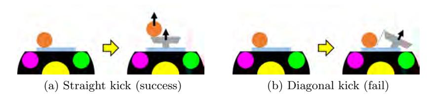
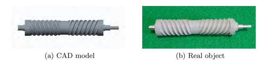
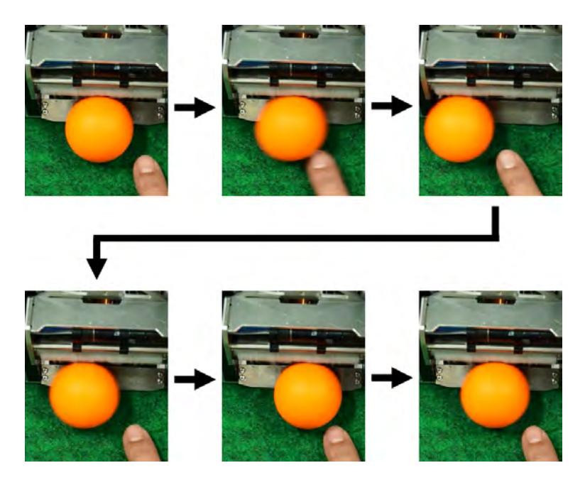
When a robot makes a straight kick, regardless of the ball position, kicking action will success (Fig. 4 (a)). However, when a robot makes a diagonal kick, kicking action may fail if the ball position is not the center of the dribbling roller (Fig. 4 (b)). In order to solve this problem, we tried to develop a dribbling roller which can carry the ball to its center automatically. We made several dribbling rollers to try, and we found the shape shown in Fig. 5 (a) has an auto centering effect. In addition, we tried following materials: soft urethane, hard urethane, soft silicone, and silicone sealant. As a result of experiments, soft urethane and soft silicone did not have enough strength, and hard urethane did not have enough grip. Finally, we found silicone sealant has enough strength and grip. Fig. 5 (b) shows the auto centering roller we developed. When this roller is spinning, lateral force works to the ball by the effect of the surface irregularities. In additional, because the center of this roller is dented, the ball stays here. This roller was made by making a pair of molds with a 3D printer and injecting silicone sealant. Fig. 6 shows how the ball is carried to the center automatically by this roller.
3 Circuit
The feature of the circuit of our robot is that each circuit is independent as a module, and each circuit is mutually connected by CAN bus. The circuit configuration is shown in the figure 7, and the main specifications of each circuit are shown in the table 2. This circuit configuration makes it easy to design each circuit as a module, and it is possible to reduce the time and labor required to deal with the case where the hardware is changed. It is also easy to add devices with arbitrary functions after the robot is completed.
Each module connected to the bus is not limited as long as it supports CAN. In this circuit, mbed is used for the main circuit module and dsPIC is used for the other module. Data sent from AI in UDP format is received by the main circuit. The main circuit decodes the necessary data and transmits the command to other modules such as the motor driver module and the kick circuit module. In addition, each module sends its own state to the CAN bus. For example, the kick circuit module transmits the state of the ball sensor and the power management module transmits the state of the battery. Information on each module required by AI is transmitted from the main circuit by wireless LAN.
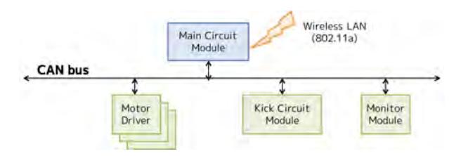
Table 2: Specifications of circuit
| Description | |
|---|---|
| MCU | mbed LPC 1768(main), dsPIC33EP64MC504(others) |
| Wireless Transceiver | Wireless LAN (IEEE802.11a) |
| Battery | Lithium polymer battery(14.4V 2200mAh) |
| Ball Sensor | IR photo IC (S6809) |
3.1 Current vector control
Current vector control is a control method often used for control of high performance AC motors. In this control method, the current is treated as a torque current component and a field current component separately. By using this control, the three-phase motor can be handled like a DC motor, and the responsiveness of the motor can be improved.
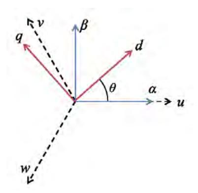
Current vector control is performed by the coordinate transformation of three vectors of uvw. The relationship between each coordinate system is shown in the fig.8. First, the vector of the uvw axis is converted to the fixed coordinate system $\alpha - \beta$ axis by following:
$$\begin{bmatrix} \alpha \ \beta \end{bmatrix} = \sqrt{\frac{2}{3}} \begin{bmatrix} \cos 0 & \cos \left(\frac{2}{3}\pi\right) & \cos \left(-\frac{2}{3}\pi\right) \ \sin 0 & \sin \left(\frac{2}{3}\pi\right) & \sin \left(-\frac{2}{3}\pi\right) \end{bmatrix} \begin{bmatrix} u \ v \ w \end{bmatrix}$$
(1)
Next, $\alpha - \beta$ axis is converted to d axis (field current) and q axis (torque current) by the following equation.
$$\begin{bmatrix} d \ q \end{bmatrix} = \begin{bmatrix} \cos \theta & \sin \theta \ -\sin \theta & \cos \theta \end{bmatrix} \begin{bmatrix} \alpha \ \beta \end{bmatrix}$$
(2)
Here, $\theta$ indicates the electrical angle of the rotor, and the d-q axis is the coordinate rotating with the rotor. As a result, the current value on dq coordinates can be handled as direct current instead of three phase alternating current. In the SPM type motor, only the q-axis component generates torque and the d-axis component does not generate torque. Therefore, the q-axis component is usually controlled to be zero.
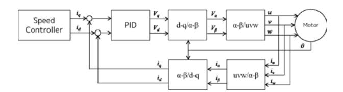
Fig.9 shows the configuration when current vector control is applied. The target current generated by the upper controller is compared with the current, and the voltage to be output (d-q coordinate) is output. $V_d$ and $V_q$ are converted into three coil voltages by the above-described coordinate transformation. Three-phase currents flowing in the motor are converted to currents on the dq axis by inverse transformation.
4 Software
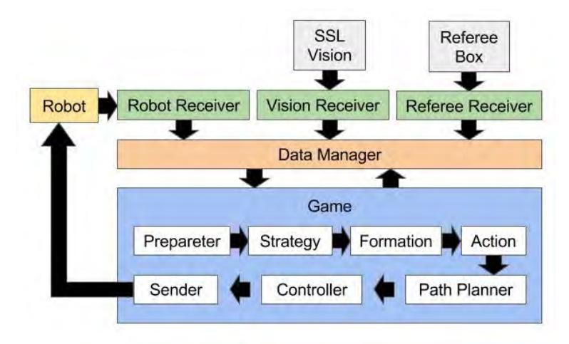
Fig.10 shows our AI system overall. This system has three receive modules, and they receive data from SSL-Vision server, Referee Box, and our robots, respectively. Received data are stored in Data Manager module for other modules. Game module has several submodules. Each of these submodules judges the situation of a game (Preparater), selects strategies (Strategy, Formation, Action) , generates routes (PathPlanner), controls the speed of the robots (Controller), and sends generated commands to robots (Sender).
4.1 Ball approaching
We employ a clothoid curve in a trajectory when a robot rounds behind a ball. The clothoid curve is given by the following :
$$x(l) = \int_0^l \cos \frac{\theta^2}{2} d\theta, \ y(l) = \int_0^l \sin \frac{\theta^2}{2} d\theta$$
(3)
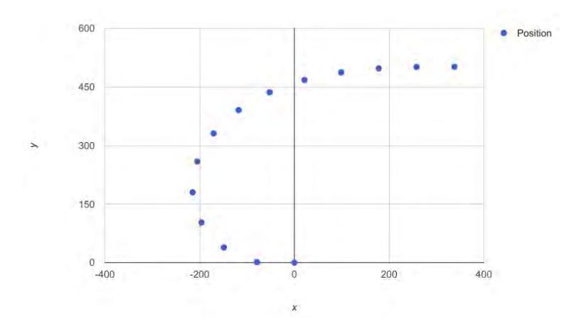
Fig.11 shows the robot trajectory, which approaches a ball position along the clothoid curve. By using clothoid curve, the robot can move smoothly based on its inertia.
4.2 Chip kick detection
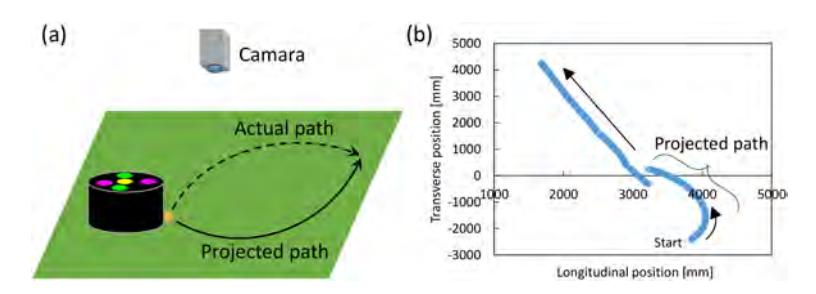
To estimate the point of fall after chip kick is an important issue to expand the AI strategy because to keep a ball has a big advantage to carry a match aggressive. As a first step to achieve this issue, to detect whether chip kick or not from its path provided by vision server is basic information. In particular, as shown in the Figure 12(a), the projected path of the chipped ball can be recognized as a curved line shown in Figure 12(b). It is far from the path of the normally kicked ball. Here, the module for chip kick detection, which installed into our AI program is introduced.
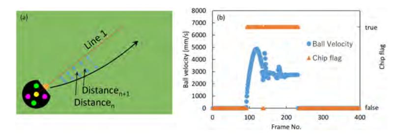
Data of the robot and ball position through the Kalman filter was obtained to define the Line 1 as shown in Figure 13(a). This line passes through the coordinate of the center of the robot and the ball. In this module, few continuous coordinate data of the ball were used to calculate the distance l between Line 1 and ball position as shown in Figure 13(a). Then these were compared with each neighboring value. And when ln+1 is longer than ln, it can judge that a projected path went away from Line 1. If this trend is seen continuously after the ball was kicked, this module detects as a chip kick and the chip flag changed to true. Figure 13(b) shows the history of ball velocity and a chip flag. A chip flag detected no signal while the ball is not moving (velocity = 0). After the ball was chipped, ball velocity increased rapidly and parabolic profile can be seen from the history. A chip flag changed to true few frames after ball velocity shows non-zero value and it is less than 0.1 s when our AI system operated at 60 fps. Although a chip kick of stationary ball was successfully detected, a chip flag is still true after bouncing. This fact means that this detection module is useful only when a game is restarted by a direct free kick, for example. In addition, a robot does not always direct to a path of a ball, further improvement is still needed. However, to combine the detection module for point of fall after chip kick, the success probability of chip pass will increase and to score on a header will also become possible.
4.3 High level controller
Velocity bounded proxy based sliding mode controller PID controllers are often used on the SSL robots because the controller is stable and responsive. On the other hand, during SSL games, target positions and speed of the robots are suddenly changed by the strategy system owing to execution of a ball tracking and an obstacle avoidance, and a threshold value of a target speed is limited by situations in the games (e.g., "stop"). PID controller may become unstable and unresponsive under the above situations.
In order to deal with these problems, we utilize a velocity-bounding proxy-based sliding mode controller (hereafter VBPSMC) [3] as a high level controller.
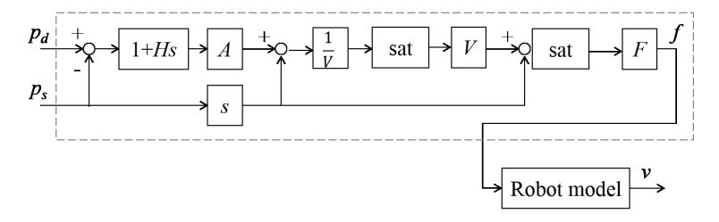
The VBPSMC is an extension of the PID controller and includes a velocity limit to modulate controller outputs. Fig. 14 shows a block-diagram of the VBPSMC with a robot model. The VBPSMC outputs force based on a difference between a target position and a robot' position, and the robot model converts the force to velocity for actual robots as a controller signal.
Parameter optimization for controllers Adjusting parameters of a controller according to field characteristics (e.g., a coefficient of friction) is important to control robots stably. However, it is not realistic to search the parameters exhaustively because we do not have much time for the adjusting.
To reduce the time for the exploration of optimal parameters for our control system, we employ a Bayesian optimization (hereafter BO) scheme [4, 5]. The BO utilizes a Gaussian process[6], which is one of probabilistic processes, to represent a relationship between parameters and evaluation values. The Gaussian process is able to suggest next search points of a parameter space by using an acquisition function. We use elapsed time as the evaluation value while a robot reaches the target points, and the BO optimize parameters on VBPSMC.
4.4 Communication system between software and robots
Our AI system not only sends control commands to robots but also receives the robots' status during games. These systems use UDP protocol to communicate each other. The AI system sends signals in 1/60 second intervals, and the robots send their status in two second intervals. Table 3 indicates a control command for the robots from the AI system, and Table 4 shows the packet of the robot' status, which the AI system receives. The control command includes an angle of a diagonal kick, which is one of the characteristics of our robot. The AI system uses the robot' status to select strategies and assign specific roles to the robots.
Table 3: Packet of control command for robots
| Data | Size |
|---|---|
| Control speed | 2 bytes |
| Move direction | 2 bytes |
| Angular speed | 1 byte |
| Direction of rotation | 1 bit |
| Dribble speed | 2 bits |
| Kick flag | 1 bit |
| Kick type | 1 bit |
| Kick speed | 3 bits |
| Direction of diagonal kick | 1 byte |
Table 4: Packet of robot's status
| Data | Size |
|---|---|
| Ball sensor signal | 1 byte |
| Battery voltage | 1 byte |
| Charger voltage | 1 byte |
| Circuit existing flag | 1 byte |
References
- http://www.asagami-works.pro/opamp/
- Takaya Asakura, Ryu Goto, Naomichi Fujii, Hiroshi Nagata, Kosuke Matsuoka, Tetsuya Sano, Masato Watanabe and Toko Sugiura.: KIKS 2013 Team Description Paper, RoboCup 2013
- Kikuuwe, Ryo, Takahiro Yamamoto, and Hideo Fujimoto. "Velocity-bounding stiff position controller." Intelligent Robots and Systems, 2006 IEEE/RSJ International Conference on. IEEE, 2006.
- Calandra, Roberto, et al. "Bayesian gait optimization for bipedal locomotion." International Conference on Learning and Intelligent Optimization. Springer International Publishing, 2014.
- Snoek, Jasper, Hugo Larochelle, and Ryan P. Adams. "Practical bayesian optimization of machine learning algorithms." Advances in neural information processing systems. 2012.
- Rasmussen, Carl Edward. "Gaussian processes for machine learning." (2006).