RoboDragons 2017 Extended Team Description
Yusuke Adachi, Hiroyuki Kusakabe, Reona Suzuki, Jiale Du, Masahide Ito, Tadashi Naruse
Aichi Prefectural University, Nagakute, Aichi 480-1198, JAPAN
Abstract This paper presents a technical overview of RoboDragons 2017, Aichi Prefectural University's team for RoboCup Soccer Small Size League (SSL). The new robots developed in 2016 are introduced. The hardware improvement over the previous generation includes bidirectional communication and non-repulsive dribbler; In the software, we implemented a novel offense strategy based on the safety region and the dominant region methods.
1 Introduction
RoboDragons is a team of Aichi Prefectural University (APU), participating in the RoboCup Soccer Small Size League (SSL). This team originated with Owaribito, a joint team between APU and Chubu University, which was founded in 1997. In 2002, as the team of each university grew up to develop the robot system by themselves, we started a new team, RoboDragons. Since then, Robo-Dragons has been participating in the SSL, including activity as CMRoboDragons, a joint team with Carnegie Mellon University in 2004 and 2005. Our best record was the second place in 2009. In addition, we finished twice in the third place (2007 and 2014) and four times in the fourth place (2004, 2005, 2013, and 2016).
This paper summarizes the system configuration of RoboDragons 2017 robots which are newly developed in 2016. We also present a novel offense strategy whose basic idea is to apply the safety region [2] and the dominant region [3] methods together to offense, The safety region method has been utilized only for defense so far.
2 Robot System
2.1 Hardware
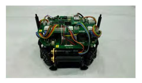
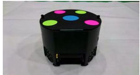
RoboDragons 2017 team introduces the seventh generation robots shown in Fig. 1. The robots were newly developed in 2016. Figure 2 and Table 1 summarize the hardware components of the robot. Most of the devices are similar to the one used in sixth generation robots developed in 2012. We use the terms 7G and 6G for 7th and 6th generation robots, respectively. The major changes from 6G to the 7G are:
- Symmetrical arrangement of omni-wheels: 6G robot arranged the front wheels and rear wheels asymmetrically; 7G robot arranged them symmetrically so as to simplify control of the robot motion.
- Cylindrical solenoid for the straight kicker: 7G robot adopted a cylindrical solenoid for the straight kicker over a rectangular solenoid of 6G. This change facilitated its fabrication.
- Dribbler with non-repulsive rubber: For the dribbler, non-repulsive rubber was introduced instead of silicon rubber so as to realize more effective cushion against the ball.
- Shockproof of Radio System Board: The radio system device was connected with the main board through a cable in 6G robot. This caused disconnection of the cable sometimes when robots collide. In 7G robot, the radio system device is directly connected to the main board without a cable.
- 4-cell HVLipo battery: The cylindrical solenoid raises the center of mass of the robot. In order to lower it, 7G robot mounted lighter battery than the one used in 6G robot. The robots become lighter due to the miniaturization of battery.
- Motion sensors: The accelerometer and gyroscope sensors were newly mounted on 7G robot.
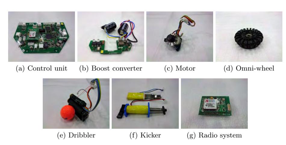
Description of main hardware components.
| Device | Description |
|---|---|
| (a) Control Unit | CPU: SH2A processor (Renesas Electronics Corporation) |
| operated with 197 MHz clock. Peripheral circuits (except | |
| analog circuits) are almost in the Xilinx's Spartan-6 FPGA. | |
| (b) Boost converter | Convert from 15.2 V DC to 150 V-200 V DC. |
| Condenser has a capacity of $4400 \mu\text{F}$ . | |
| Charging time is about 3s (when output voltage is 200 V). | |
| (c) Motor | Maxon "EC 45 flat 50 W". |
| Gear reduction ratio between motor and omni-wheel is 21:64. | |
| (d) Wheel | 4 omni-wheels, each has 20 small tires in circumference. |
| Diameter: omni-wheel 55 mm, small tire 12.4 mm. | |
| (e) Dribbler | Dribble roller: 16 mm in diameter and 61 mm in length, |
| made of aluminum shaft with non-repulsive rubber. | |
| Motor is Maxon "EC 16 30 W". | |
| (f) Kicker | Kick bar is made of 7075 aluminum alloy. |
| Solenoid is a coil winding $\phi$ 0.6 mm enameled wire. | |
| Straight kicker kicks a ball with over 8 m/s at maximum. | |
| Chip-kicker kicks a ball as far as 3 m distance at maximum. | |
| (g) Radio System | IEEE 802.11abgn 2.4/5 GHz wireless LAN. |
| Ball detector | Infra-red light emission diode and photo diode pair. |
| Motion sensors | Accelerometer: BOSCH BMA250 |
| (3-axis (range: $\pm 2 \mathrm{G}$ to $\pm 16 \mathrm{G}$ )) | |
| Gyroscope: InvenSence ITG3400 | |
| (pitch, roll & yaw (range: $\pm 250 \mathrm{deg/s}$ )) |
2.2 Software
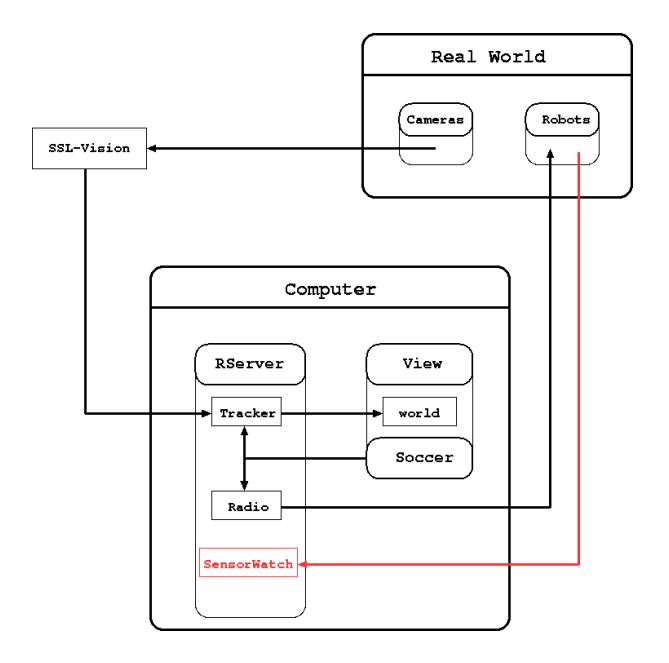
Figure 3 shows an overview of our software system. Our software system is mainly composed of the following three modules (Rserver, View, Soccer):
- The Rserver module receives the data from the SSL-Vision system, and then the Kalman filter in the Tracker submodule estimates the positions of the ball and robots. The estimated positions are shared among all modules. The Rserver also sends the command packet to each robot through the Radio submodule.
- The View module is a graphical user interface module. It displays the current soccer state that a human operator wants to know, and takes commands from the operator.
- The Soccer module generates an action command to each robot. This module chooses the best strategy for the current situation, assigns each robot a role based on the chosen strategy, and computes a motion command to perform the role for each robot.
This year, we introduced a bi-directional communication between the host computer and each robot in order to exploit the data from the above-mentioned motion sensors. In particular, we updated Rserver and the communication packet partially. The SensorWatch submodule we newly added into Rserver receives the information from the robots; The configurations of the communication packets are shown in Tables 2 and 3. One bit of the command packet was assigned for turning on/off the bi-directional communication mode. If this bit is turned on, the host computer receives the observation packet from each robot.
3 New Offense Strategy based on Unsafety Region
Maeno, et al. [1] have proposed a "safety region" which is defined as a region that the teammate robots can prevent from scoring a goal from the opponents' attack. This works as an index for positioning the defense robots. Inagaki, et al. [2] made this method more accurate.
The region on the soccer field other than the safety region is called an "unsafety region". Based on the unsafety region, we present a novel offense strategy in this section.
Configuration of the command packet to each robot
| Config. | Description |
|---|---|
| 1st byte aaaabbbb aaaa: Robot ID, bbbb: Robot velocity (Upper 4bits) | |
| 2nd byte bbbbbbbb Robot velocity (Lower 8bits), 0–4095 mm/s | |
| 3rd byte cccccccc Moving direction (Upper 8bits), Resolution is 2π/512 rad | |
| 4th byte ddddefff dddd: Dribble velocity, e: Rotation direction, fff: Angular | |
| velocity (Upper 3bits) | |
| 5th byte ffffffff Angular velocity (Lower 8bits), 0–2047 deg/s | |
| 6th byte gggggggg Kick force, 256 levels | |
| 7th byte chhh000i c: Moving direction (Last bit), hhh: Normal/Forced kick, | |
| i: bi-directional communication flag | |
| 8th byte jjjjjjjj CRC code |
Configuration of the observation packet from each robot
| Config. | Description | |
|---|---|---|
| 1st byte | aaaabbbb aaaa: Robot ID, bbbb: Robot Index Number | |
| 2nd byte cccccccc Motion Sensor Z (Upper 8bits) | ||
| 3rd byte | cccccccc Motion Sensor Z (Lower 8bits) | |
| 4th byte | dddddddd Motion Sensor X (Upper 8bits) | |
| 5th byte | dddddddd Motion Sensor X (Lower 8bits) | |
| 6th byte | eeeeeeee Acceleration Sensor X (Upper 8bits) | |
| 7th byte | eeeeeeee Acceleration Sensor X (Lower 8bits) | |
| 8th byte | ffffffff Acceleration Sensor Y (Upper 8bits) | |
| 9th byte | ffffffff Acceleration Sensor Y (Lower 8bits) | |
| 10th byte gggggggg Acceleration Sensor Z (Upper 8bits) | ||
| 11th byte gggggggg Acceleration Sensor Z (Lower 8bits) |
3.1 Computation of Safety Region
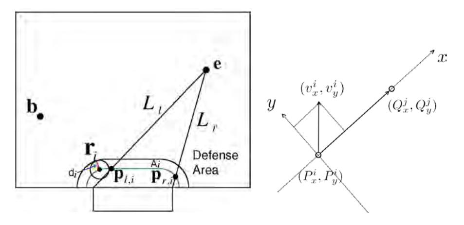
Computing the safety region implies that the unsafety region is also obtained. This subsection briefly provides how to compute the safety region. See [2] for further information. The variables used for computing the safety region are defined in Table 4 and Fig. 4. The following algorithm computes whether the goalkeeper can keep the goal or not (The green curve A^i in Fig.4 is a curve along the border of the defense area with the distance d^i which is a radius of the goalkeeper robot). It is assumed that the ball b is passed to e, then shot.
- Step 1 Divide the field into n grid points.
- Step 2 For each grid point, do following step with the given ball position.
- Step 3 For given two line segments L^r and L^l connecting e and the right/left side of the goal, respectively, compute the following inequalities;
$$D_{j,i} < \frac{1}{2}a_i(t_p + t_s)^2 + R \quad (j = r, l). \qquad (if \ t_i > t_s)$$
$$D_{j,i} < \frac{1}{2}a_it_i^2 + v_i(t_p + t_s - t_i) + R \quad (j = r, l). \quad (Otherwise)$$
If at least one of the inequalities is satisfied, the point e is a point of the safety region, otherwise a point of the unsafety region.
Definition of variables
| di | the radius of robot i |
|---|---|
| R | sum of the robot's and ball's radii |
| b | current position of the ball |
| e | position at shooting the ball at time t (grid point) |
| ri | position of robot i |
| vi | maximal linear velocity of robot i |
| ai | maximal linear acceleration of robot i |
| pj,i | position where the robot i blocks the shot (j = r, l) |
| ti | time for acceleration from 0 to vi at ai |
| tp | time for passing from b to e at velocity vp |
| ts | time for shooting from e to pj,i with velocity vs |
| Dj,i | the distance between ri and pj,i |
3.2 Using Unsafety Region and Dominant Region
The algorithm presented in the last subsection provides not only the safety region but also the unsafety region. In addition, we need to predict which team can first reach the ball. For such prediction, the "dominant region" proposed in [3, 4] is effective. The computation of the dominant region can be simplified when the unsafety region has been already obtained. We compute the following simplified equation for each robot in the field to estimate which robot can reach the ball first (see also Fig.4):
$$Q_x^j = \frac{1}{2}a_x^i t^2 + v_x^i t + P_x^i \tag{1}$$
where, (Q^j x , Q^j y ) is a point in the Unsafety Region. (P i x , P^i y ) is a current position of the robot i. (v i x , v^i y ) is a current velocity of the robot i. (a i x , a^i y ) is the max acceleration of the robot i. Coordinate system is taken as shown in Fig.5. We estimate arrival time by Eq.(1) for simplicity. For each point (Q^j x , Q^j y ) in unsafety region, estimate the arrival time t^i for each robot i by Eq.(1). A robot with minimal estimated arrival time dominates the point. If the robot is a teammate robot, the point is a point of the teammate's dominant region. To improve the estimation accuracy, we have to introduce the estimated maximal velocities of the robot into Eq. (1) , which is not implemented yet.
3.3 Offense strategy in set play
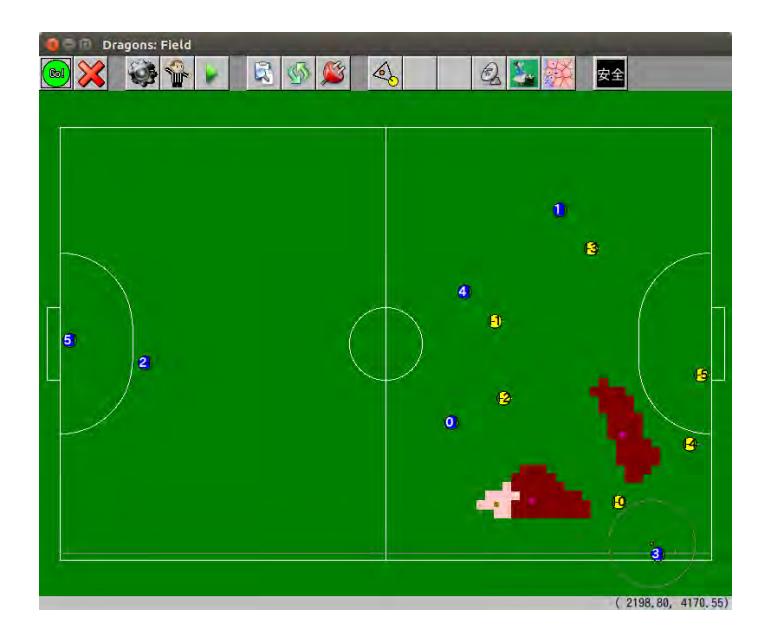
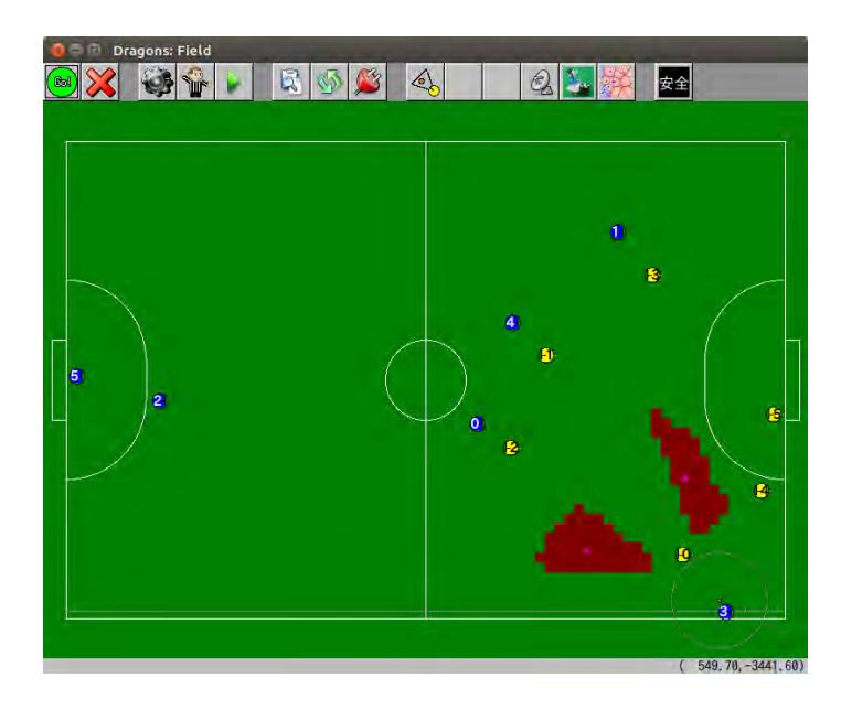
In this subsection, we apply our method to an offense strategy in a set play and show examples of the simulation results. Fig.6 shows an examples of a computation result at the time after waiting for a few seconds until robots are steady in a set play. In this example, we have a dominant region (pink area) in unsafety regions (pink + brown area), therefore we will pass the ball to the robot that makes the dominant region. On the other hand, if we have no dominant region in unsafety region as shown in Fig.7, we should select an other action to lead to the dominant situation.
4 Concluding Remarks
We have presented the system configuration of RoboDragons 2017 robots. The main points of our contribution are to introduce new robots and to propose a novel offense strategy based on the safety region and dominant region. The proposed offense strategy will make the set play more dynamic.
References
- J. Maeno, A. Ishikawa, K. Murakami, and T. Naruse: "Safety region: an index for evaluating the situation of RoboCup Soccer game," JSAI Technical Report, SIG-Challenge-B001-2, 2010, http://winnie.kuis.kyoto-u.ac.jp/ sig-challenge/SIG-Challenge-B001/SIG-Challenge-B001.html (in Japanese)
- T. Inagaki, A. Ishikawa, K. Murakami, and T. Naruse: "Robust algorithm for safety region computation and its application to defense strategy for RoboCup SSL," The 15th annual RoboCup International Symposium (2011)
- R. Nakanishi, J. Maeno, K. Murakami, and T. Naruse: "An approximate computation of the dominant region diagram for the real-time analysis of group behaviors," The 13th annual RoboCup International Symposium (2009)
- A. Ishikawa, T. Sakai, J. Nagai, T. Inagaki, H. Sawaguchi, Y. Nunome, K. Murakami, and T. Naruse: "RoboDragons 2010 Team Description," RoboCup Soccer Small Size League (2010)
- Y. Adachi, H. Kusakabe, N. Tsuzuki, H. Hayama, D. Yamaguchi, M. Ito, and T. Naruse: "RoboDragons 2016 Extended Team Description," RoboCup Soccer Small Size League (2016)