RoboIME: on the road to RoboCup 2017
Carla S. Cosenza, Gustavo C. K. Couto, Luciano de S. Barreira, Luis D. P. Farias, Luis R. L. Rodrigues, Jan L. L. Segre, Matheus C. Castro, Nicolas S. M. M. de Oliveira, Onias C. B. Silveira, Renan P. de Souza, Victor Bramigk, Yugo Nihari, Paulo F. F. Rosa
Instituto Militar de Engenharia, Rio de Janeiro, Brasil
Abstract This paper describes the electronic, mechanical and software designs developed by the RoboIME Team in order to join the RoboCup 2017. The overall concepts are in agreement with the rules of Small Size League 2017. This is the fourth time RoboIME participates in the RoboCup.
1 Introduction
RoboIME is a Small-Size team from the Instituto Militar de Engenharia, IME, located in Rio de Janeiro, Brazil. This is the ninth time the team takes part in competitions, being the best results two second places in RoboCup Brazil Open 2011 and in Latin American Robotic's Competition 2012.
All students that work in the SSL project are members of IME's Laboratory of Robotics and Computational Intelligence. Team's previous works were used as reference [5] [4], as well as the help from former members of the team as consultants and tutors.
This article describes the team's general information and improvement in the most two recent years, in all topics: computational, electrical and mechanical. They are organized as such: software in section 2, electric in section 3 and mechanical in section 4. Conclusions and future works are discussed in section 5.
2 Software Project
Our current Software is developed in LabView 2016 because of its scalability potential and the tools it provides for measurement of physical entities and for graphical analysis of our system.
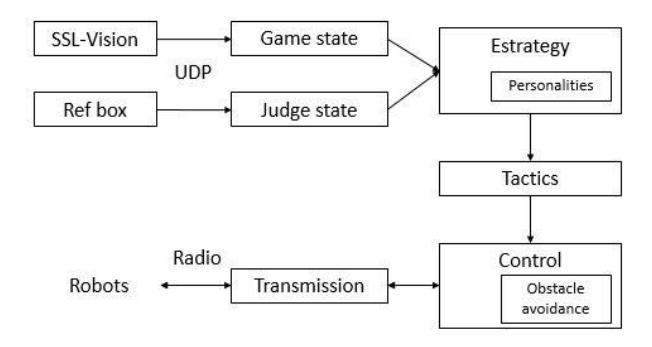
The Software's information flow - as depicted in figure 1 - is composed of five stages: Reception, Pre-processing, Decision Making (Artificial Intelligence Module), Control and Transmission. In Reception, packages from the SSL-Vision and the Ref box are received. The packages are further independently pre-processed in two modules: Gamestate and Referee. In Gamestate the Vision information is filtered using a Kalman Filter. The Control stage, in which is received commands from the AI system, perform algorithms in order to control the robots' movement by calculating proper velocities. Further, in the Transmission stage, the Transmission module sends the proper velocities to each robot so they can perform the desired movement. The decision-making stage, which is composed by Strategy (Personalities Module) and Tactic is further described.
2.1 Game state
Estimation using Kalman Filter One improvement of the 2016 version was the addition of a Kalman Filter, which uses available data to estimate more precise values and obtain information that was not available before (A good starter reference for kalman filters is found at [3]). A kinetic model is applied in the objects, which improves our instantaneous values of position, velocity and acceleration and helps predict future situations, even without the SSL-Vision's aid. Further work can be included in this filter, such as receiving velocities from the robots themselves.
2.2 AI System
Personalities Our current AI system architecture starts by receiving the previously pre-processed information from the Vision system and thus performs a heuristic algorithm to assign a personality for each ally robot in the field. There are three main personalities - Attacker, Defender, and Goalkeeper -, and each of them performs a different role accordingly to the current Referee State. The main behaviour of each personality is defined in our Tactic module, described as follows:
Tactic Module
– Attacker: As for defining the attacker role's main behaviour, a simple heuristic algorithm is performed:
With the information provided by the visual system, it is possible to estimate the gaps in the enemy goal, thus to determine a set of intervals in the goal to which the Attacker shall kick the ball in order to score. The larger intervals middle point is set to be the target point. In order to avoid tilting, each target point has a lifespan.
After being calculated the target point, it is applied the GoTo method to set the Attackers velocities in order to position the robot properly to shoot at the target point, whether the robot already has the ball possession or not. If the distance of the Attacker to the ball is close enough and the Attacker is as well positioned as desired, the Attacker robot is set to kick the ball.
- Defender: The main strategy of the defense is to create a wall of robots. In order to accomplish that, the first robot assigned to the defense will occupy the intersection of the line, which connects the center of the goal and the ball, with the circle whose center is the middle of the goal and has a radius of r +l +d, where r is the radius of the robot, l is the distance from the goal to the beginning of the goal semicircle and d is the radius of that semicircle. Other robots assigned to the defense will alternatively occupy each side of the blockade along the circle previously stated with a distance of 2r from the closest robot. This will prevent the ball from reaching the goal because the wall of robots will always be in synchronization with the ball.
- Goalkeeper: The main role of the Goalkeeper is to intercept the ball before it reaches the goal. Therefore, when the enemy has ball control, the goalkeeper stays where the enemy robot, which has the ball, is looking at. If this position is outside the goal, it stays as close as possible to the goal end. If the enemy is not controlling the ball, yet the ball is moving towards our side (e.g. after a kick), the point where the ball would hit our goal is calculated and the goalkeeper is assigned there. If this point is outside the goal, it stays at as close as possible to the goal end.
2.3 Control
Obstacle Avoidance In order to avoid collision with other robots, the Potential Field algorithm is used. (Further reading can be found at [7]) For every ally robot, it is computed the other robots' influence described by the potential field model. Furthermore, the ally robot's velocities are hence updated. Even though this algorithm doesn't guarantee the robot won't be trapped, it is simple to implement and it has been shown to be an efficient approach for obstacle avoidance in highly dynamic environments.
3 Electric Project
[Section contents begin with subsections below]
3.1 Firmware
For LARC 2016, the team developed a new firmware in C++ applying concepts of hardware abstraction and object orientation. Thus, there are abstract classes, representing the robot's sensors, actuators and it's microcontroller resources, and concrete classes, which implement the methods defined in the abstract classes. This way, the firmware becomes closer to a development platform that can be studied, improved and can support changes as well as serving as a foundation to new projects.
The firmware is embedded in a STM32F4 Discovery board with an ARM cortex-M4 microcontroller [9]. The C++ language was chosen due to it's object oriented nature, as well as other benefits to the project, such as inheritance and polymorphism.
The main functions of the firmware are receiving and sending information to our computer and the control over the robot. The communication occurs inside an infinite loop, while the control is performed through interrupts.
Abstract classes The functionality of classes is declared by abstract classes and implemented by specific codes for each hardware. For example: abstract class motor, implemented by the classes motor brushless and motor ponteH
The firmware has the following classes that implement funcionalities: [2]: GPIO (sets usable IO pins), SPI, ADC (analog to digital converter), PWM, InterruptTimer (implements an interruption through a timer), Encoder, Motor, Robo (implements an interface to all robot's sensors and actuators), NRF24L01P (transmits information between computer and robot).
Communication The firmware has classes dedicated to implementing communication via serial and uses a library called nanopb for serialization.
- USB DEVICE CLASS CDC VCP implements a virtual COM port (VCP), with one circular buffer for transmission and one for reception. The VCP is used to send commands to the robot and get information about the wheel speeds in a test mode, through a command line interface(CLI).
- USB STM32 represents the Discovery's USB peripheral. The microcontroller has an OTG FS controller, which is fully compliant with the On-The-Go Supplement to the USB 2.0 Specification. The USB device is used in order to emulate a virtual COM port.
- PROTOBUF The nanopb library [2] is used to encode the information transmitted via radio or serial port.
- Nanopb is an ANSI-C library for encoding and decoding messages in Google's Protocol Buffers [6] format with minimal requirements for RAM and code space. It is primarily suitable for 32-bit microcontrollers [1].
Communication in LabVIEW In the project's main file, clusters are continuously read. Those clusters represent our team, the opponent team, positions where the ball was detected, field's geometry, information from the referee and the received Time Stamp. A vector with information about our team is extracted from a cluster, is converted to a vector of grSim Robot Commands and is sent to transmission, via UDP (transmits to grSim) or via serial (encoding it using protobuf and then writing the COM port implemented in a Discovery board dedicated to transmit to robots).
3.2 Control
Maintaining the robot at the expected speed or position is very important so that the software project works properly. To try to keep the robots moving as expected, there are several routines to check or filter the results obtained from the vision system and the robots themselves.
Dealing with wheel slippage The robot may have one or more slipping wheels, which is problematic because it makes the robot to deviate from it's intended path.
To correct this, first we need to know the relations between the speed of the wheels, vector v, and the speed of the robot itself, vector v, and the forces applied to the motors, vector f, and the robot's acceleration, vector a. Calling D the matrix that relates m and v, m = Dv, and Cα the matrix that relates f and a, a = Cαf. To determine if slippage occurs, we calculate D's pseudo-inverse matrix, B, and then compute (I −D·B)·m. If it results zero, there is no slippage and the speeds are considered correct. If not, we use Cα's kernel to remove the component of forces that are generating the same acceleration. Slippage occurs when are any wheel speeds in the direction of Cα's kernel. Applying Gram-Schmidt in vector m we remove any component in direction of the kernel, but in consequence we change the overall direction of the robot. To align with the original correct direction, we just need to take the projection of the corrected speed vector in the original direction. [8]
Determining new PID constants Effort is being put into finding more appropriate control constants. The Ziegler-Nichols method and a further study of our robot's physical model are being used together to help optimize our PID constants.
To apply Ziegler-Nichols' method to our wheels, LabView is being used to plot the velocities registered by our motor's encoders and sent to the computer through a serial port. For the robot as a whole, there are three more PID sets of constants to be found: regarding forward movement, sideways moves and rotations in it's own axis. The difference between forward and lateral constants are due to an purposed asymmetry in our robot's design.
3.3 Board Designs
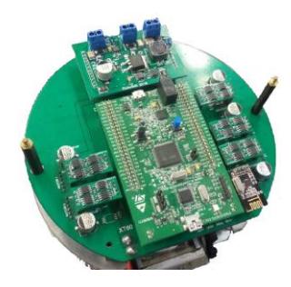
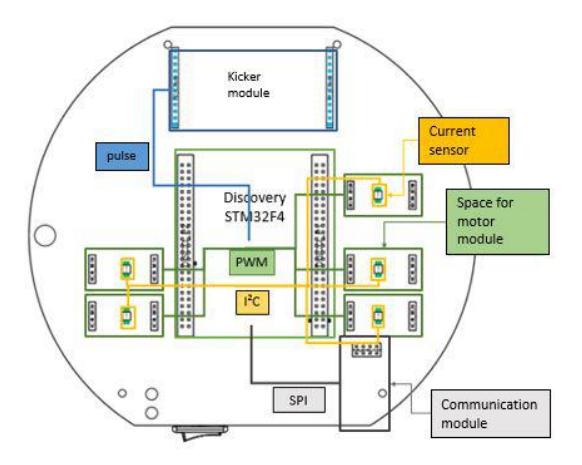
RoboIME's hardware platform can be described by it's modules: the motor module, that gives power to each of the robot's motors, the kicker module, that creates and maintains high voltage in capacitors and delivers the stored power to the coil to activate the kick mechanism, the stamp module, that performs the embedded computation, the main board module, that provides the modules physical connections and the communication module, that sends and receives data to the intelligence, figure 2.
The advantages of a modular hardware design are that it's friendly for the maintenance of the project. In addition, two of the modules are commercial and open source boards, the stamp module is a STM development micro controller board and the communication module is a generic breakout for the NORDIC 2.4 GHz nrf24l01p transceiver.
For the last LARC competition, new designs were made for the modules but kept the same architecture, focusing the changes in optimizing the position of the components, improving the route's dimension and substituting outdated components.
4 Mechanical Project
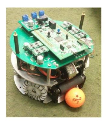
This robot was and is being designed using the CAD (Computer Aided Design) and CAM (Computer Aided Manufacturing) softwares. Tests and analysis are being made to improve the project that was received from former members of the team, especially on:
- Making the project more concise, focusing on facilitating the production of parts and removing unnecessary ones;
- Fabricating a more efficient, it is necessary to improve precision of the control and to make the parts more resistant.
With these objectives in mind, most of the modifications were made on the dribbler and the kicking system.
Majority of our components are produced using the CNC (Computer Numeric Control) method, made of 70-75 aluminum, a material that presents a high mechanical resistance and is easily milled. Besides, there are also parts made of brass, cut by a metal lathe, while the remaining are made by a PLA or ABS 3D printer.
4.1 Productions Methods
Jet cutting The chassis and the superior support, which divides the electronic components and the battery from the remainder of the robot, are manufactured using jet cutting. Those parts use aluminum plates of 3mm and 2.5mm, respectively.
CNC milling machine Most of our components are fabricated using a CNC milling machine. Beforehand the milling process itself, it is necessary to make the CAM in order to generate the code for the machinery. Some parts are extremely challenging due to their reduced size and complexity. These two factors affect mostly their measurements, in order to preset the origin, and the manner that they are placed safely in the machinery, especially during the last stages of production.
![[Continued from Figure 4]](/tdps/soccer_smallsize__2017__RoboIME/_page_8_Picture_2.jpeg)
4.2 Kick
Both the low and high kicks underwent minor alterations so that the milling could become easier and simpler.
The low kick consists of a kicker, an axis of the low kick, a piston, a frontal support of the solenoid, a rear support of the solenoid and a solenoid.The high kick consists of a kicker, a single support for the solenoid, a piston, a solenoid and a support for the restrain of the piston. Both are activated by two capacitors that energize the solenoid, making the piston, which is incorporated with the kicker, thrust forward.
The current project uses elastic bands to bring the piston back in place due to their price and their efficiency in the process. On the other hand, the low kick uses a conic spring.
4.3 Dribbler
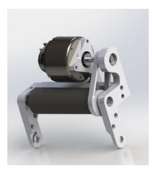
The design of the dribbler, figure 5, has been improved to yield a better result. On its older version, the height of the chassis needed to be adjusted so that the dribbler could hold the ball but this left the chassis too close to the floor, which hindered the movement of the robot. Another problem of the former project is that sometimes the ball would not spin even though the adapter of the motor of the dribbler and the pulley did slide. To solve this, these two parts have been transformed into one that is connected to the axis of the motor, resulting in the spinning of the ball on the field. Finally, the last issue encountered was an O-ring used to transmit the pulley to the roller of the dribbler. This ring was tensioned a great deal, which made the axis of the motor bend, damaging it.
4.4 Transmission system
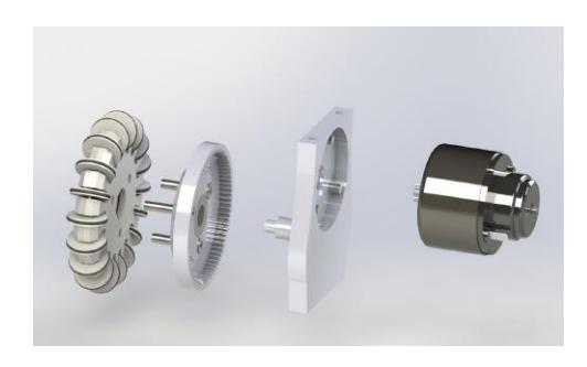
A system of internal gears was made to transfer the power of the motors to the wheels. This system brings many advantages when compared to the traditional method, like avoiding the entrance of debris in the motors, creating a cavity to apply grease for the lubrication of the gears and a smaller size, for example.
However, there were some difficulties on the fabrication of this component, especially due to the small size of the teeth, which need to fit on the gear of the standard motor (the motor used is the Hsiang Neng DC brushed motor of type HN-GH35GMB). In this motor, the distance between two consecutive teeth is smaller than 1mm, making the milling complicated.
This part was first produced using the 3D printer of deposition of filament to print the piece in ABS plastic. Yet, these pieces did not present good results as they broke very easily and did not exhibit a smooth movement, stopping their rotation if the force provided was not significant, which prevented a good control of the robot. This problem was minimized altering the printing method to one of stereolitography, which is when a beam of laser solidifies a liquid resin layer per layer, in order to get a good movement. However, the resistance dilemma was not completely eliminated.
The idea of this updated project is to mill a mold, which will help produce the components with injection of ABS plastic, a piece of plastic that is made by high pressure injection, presenting a better resistance than one produced by impression. To obtain a good precision, the negative of the gears teeth will be made by electrical discharge.
Even though this option is complex and involves a lot of work due to the creation of the mold, it will result in an extremely quick and cheap production.
5 Conclusions
For the this competition, we are aiming into continuing the progress established last year: experimenting a new approach to the software project, modularizing the electrical project and producing more reliable CADs and CAMs in the mechanical project.
5.1 Acknowledgement
This research was partially supported by the Army's Department of Science and Technology (DCT), Fundação Carlos Chagas Filho de Amparo à Pesquisa do Estado do Rio de Janeiro - FAPERJ(grant E-26/111.362/2012); Fundação Ricardo Franco (FRF) and Fábrica de Material de Comunicação e Eletrônica (FMCE/IMBEL). The team also acknowledges the assistance of Clara Luz de S. Santos and Jorge L. de Castilho Jr from FMCE. Special thanks to all former members of RoboIME. Without their support, this team would not be here.
References
- Nanopb: Protocol buffers with small code size documentation index. https://jpa.kapsi.fi/nanopb/docs/index.html
- Petteri Aimonen. https://github.com/nanopb/nanopb
- Bzarg. http://www.bzarg.com/p/how-a-kalman-filter-works-in-pictures/, 2015.
- Jan L. L. Segre Lucas O. de Lima Naum A. F. Barreira Victor Bramigk Gustavo C. K. Couto Renan P. Souza Luis D. P. Farias Onias C. B. Silveira Rebeca C. Brito Carlos A. D. Pinto Johnathan F. Rosa Paulo F. F. Rosa. Roboime: on the road to robocup 2016.
- Carla S. Cosenza Clara L. de S. Santos Gustavo C. K. Couto Jan L. L. Segre Johnathan F. da Rosa Luciano de S. Barreira Luis D. P. de Farias Luis R. L. Rodrigues Matheus Bozza Onias C. B. Silveira Renan P. de Souza Paulo F. F. Rosa. Roboime: Team description paper.
- Google. Protocol buffers. https://developers.google.com/protocol-buffers/.
- Ramon Jansen. Waypoint navigation with obstacle avoidance for mav's. 2016.
- Raul Rojas. Omnidirectional control. 2005.
- Discovery STM32F4. http://www.st.com/en/evaluation-tools/stm32f4discovery.html, 2016.
- Andre Ryll Nicolai Ommer Mark Geiger Malte Jauer Julian Theis. Tigers mannheim, team description for robocup 2014.