RoboTeam Twente 2017 Team Description Paper
Ewoud Croll, Rik Freije, Klaas de Haan, Hans van der Heide, Jim Hoekstra, Boi Okken, Roel Plompen, Bob Rubbens, Rick Timmer, Stefan Tolboom, Dennis de Weerdt, Iris Weijers, Wybe Westra
University of Twente, Netherlands
Abstract This paper describes the hardware and software of RoboTeam Twente, which intends to participate in the RoboCup 2017. The team was founded in 2016 and hence this is the first attempted qualification and Team Description Paper. All the basics of the robot will be explained in detail, as well as some possible improvements not yet implemented by the other teams.
1 Introduction
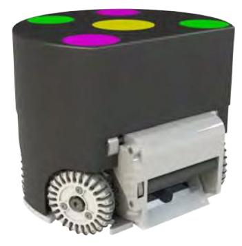
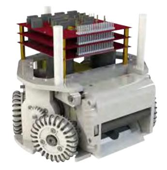
With no old hardware and software to start with, the main focus this year lies on preparing the robots in time for the RoboCup 2017. To not waste any time, prototype robots from acrylic glass were developed for the qualification. However, this paper will not focus on these robots but on the final robots which will be used in the RoboCup, see Fig. 1. Partly thanks to the RoboCup being open source, a lot has been established the past months. This brought this year's team closer to their competitive goal: participating in the RoboCup 2017. While it may not feature a lot of innovation it does give a lot of detailed information about the robots. This can hopefully help new teams in the future with building their first generation robots.

2 Mechanics
In this section the mechanical design and construction of the robots will be explained. All individual components will be described one by one. To reduce weight the majority of the pieces will be made from polyoxymethylene (POM). This material has half the density of aluminum and is characterized by its high strength, hardness and stiffness. Most components are manufactured with the aid of CNC milling and turning machines as well as a laser cutting machine. The open-source hardware of TIGERs Mannheim was used as a guideline for most of the parts.
2.1 Wheels
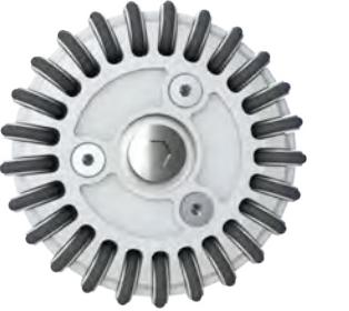
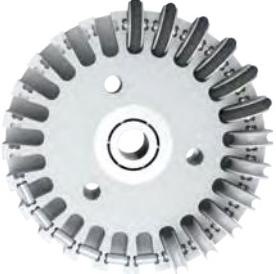
General. For the omnidirectional wheels the MRL 2012 design [1] was used as a base, renders can be found in Fig. 2. The dimensions, however, do differ and can be found in Table 1. The large amount of small wheels should make for a smooth ride. The wheel itself and small wheels will be made from POM. The small axles are made from hardened steel and can turn freely in their chamber, just like the small wheels can on the axles. This makes the small wheels turn with very little friction. The EPDM rubber O-rings produce grip for the robots. The wheel has chambers to remove some weight.
Table 1: Wheel dimensions
| Dimensions | Values |
|---|---|
| Diameter [mm] | 55 |
| Width [mm] | 12.5 |
| Number of wheels | 25 |
2.2 Dribbler
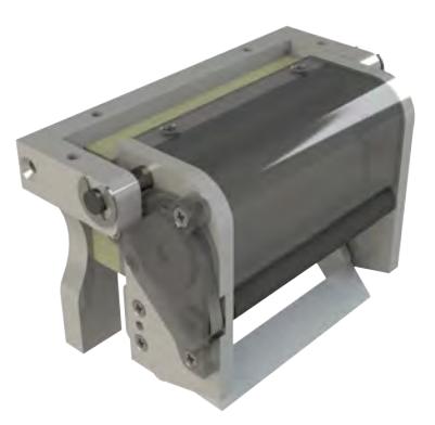
The dribbler bar has a length of 71 mm and a diameter of 10 mm. The small diameter gives the ability to dribble 'high up' on the golfball, without exceeding the 20% rule. Just like [2], a timing belt is used rather than plain gears. Given the high amount of rpm the dribbler bar has to make, this seems to be the logical choice. A T2/90 belt is chosen with timing belt gears with respectively 34 and 13 teeth. More information about the motor used is stated in Sect. 3.1.
For better pass receiving the dribbler is hinged and damped with foam. This does not help enough when the ball touches the side of the dribbler. For this case a solution is still to be found, one possibility is the use of high impact damping foam. A render of the current design is shown in Fig. 3. Two parts are made transparent to reveal the parts behind them.
2.3 Kickers
General. Like most teams, a straight kicker and chip kicker are used, both explained below. More information about the electronics of the kickers can be found in Sect. 3.5.
Straight Kicker. The straight kicker will not differ from most teams' design. Right now modified retail solenoids are used, testing will have to show whether these suffice. At the moment the kicker shoots straight because of the nonsymmetrical shape of the plunger, which is forced trough a piece of plastic with the exact same shape. Research will be done into solutions with less friction.
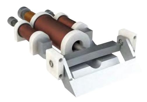
Chip Kicker. The chipper is mounted to the dribble system to cancel out the influence of the damping action. Without this the ball would have a variable position relative to the chipper which makes it impossible to shoot consistently. Instead of using a flat solenoid, two small solenoids are used which fire at the exact same time. Details on the complete kicker setup can be found in Fig. 4.
2.4 Frame
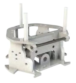
Inspired by TIGERs Mannheim [3] the motor mount, motor and wheel can be taken out together as one block to make replacements easier. Unlike TIGERS Mannheim, a 'middle ring' is chosen to add some extra stiffness. Yet again, all components will be produced from POM. A render can be found in Fig. 5.
2.5 Case
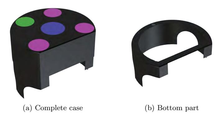
The case will be split into two parts, one mounted on the middle ring and one at the top. This makes the case easily manufacturable by vacuum molding, while still being strong. The mounting will be done with magnets to make for easy replacements of parts and batteries. Figure 6 shows a render of the case.
3 Electronics
3.1 System Overview
General. The electronics of the robot are configured in a modular way. This way, a sub-module will be easily replaceable when it fails, even during a match. Most components are chosen based on being easy to implement or work with.
Currently, the modular system consists of three stackable printed circuit boards (PCBs); the main controller board, motor controller board, and kicker board. They will use a common connector for communication buses and power supplies (excluding high voltage). The subdivision separates the logic from the power and high voltage electronics. In addition to assuring safety, it also increases reliability and ease of replacement for components that are more likely to fail, such as motor controller power electronics.
The choice of motors in SSL robots is critical. Due to the lack of space, and relatively high acceleration rates and speeds, the only realistic option is the use of a brushless motor. Either the Maxon EC45 flat 30W or 70W variation seems to be the best choice. Considering this is the first year for RoboTeam Twente, the 30W was selected for more simplicity. THe 70W variation requires other driver electronics. For the dribbler the Maxon DCX26L GB SL 12V are used, the specifications here are less important.
Next to the electronics on the robot, there is a base station connected to the computer to provide communication between the tactics computer and all robots on the field. The communication itself is handled with off the shelf available 2.4Ghz transceiver boards. The NRF24L01 was picked for availability, price, robustness and ease of use.
Design Specifications. To help determine design boundary conditions, general design specifications were made up and used in the design of sub-modules. These are shown in Table 2 below. Note that most of these specifications are not fully fixed and can be changed.
Table 2: General electrical design specifications of the robots/system
| Specification | Value |
|---|---|
| Maximum power draw [W] | 140 |
| Maximum power draw (per motor) [W] | 30 |
| Nominal common (battery) voltage [V] | 12 |
| Maximum common (battery) voltage [V] | 20 |
| Operating temperature range (ambient) [C] 0 to +60 | |
| Wireless communication frequency [GHz] | 2.4 |
| Maximum kicker voltage [V] | 400 |
| Maximum ball speed [m/s] | 8 |
3.2 Basestation
For the basestation communication, a PCB was developed in which an STM32F3 Discovery board can be plugged in directly. This simplifies board design and minimizes cost time spent debugging and complexity. The other components used in the PCB are debug LEDs, switches and four spots for the NRF24 modules. The communication protocol between the base station and the tactics PC is a simple acknowledge protocol based on the packet format as described in [4].
3.3 Main Controller Board
Overview The top board of the robot contains the main controller. The main components making up the main controller board are: an ARM Cortex-M4 STM32F3, an Xsens MTi-100 gyroscope-accelerometer package, a Mach X02 FPGA, a NRF24L01 wireless module, a bus connector that connects to the other boards, connections to the dribbler, and some debug LEDs/buttons. The wireless module sets an interrupt pin when it has received instructions from the basestation and sends these instructions via SPI to the microcontroller. The microcontroller is in charge of processing commands and acting on them. It controls the kicker board, the dribbler motor and the ball detection directly. It also calculates the individual rotational velocity setpoints by combining the commands and the information provided by the inertial navigation MTi unit. That information is sent to the FPGA. The FPGA is in charge of controlling the four BLDC motors simultaneously. It uses velocity control to assure the desired rotational motor velocities are met. The signals the FPGA produces are fed through to the motor controller board power electronics via a header stack.
STM32F3 The STM32F3 series is an excellent fit for controlling the robot. The floating point unit in the chip makes sure that trigonometric and differential equations can be performed quickly. The flash memory of 64kB ensures that even the most complex program and code structure can fit easily.
FPGA The FPGA selected for the control and commutation is the Lattice MachXO2. Microcontrollers were considered for the task, but there are too few PWM outputs and GPIOs available on almost all microcontroller packages to control all motors at once. The price of the microcontrollers that do have enough, are generally just as expensive as an FPGA. Considering this and that the commutation is a task that is inherently well done in hardware, an FPGA was selected.
Timing requirements are not precise in the robot, so the FPGA can use its internal oscillator. It features an on-board voltage regulator, thus instead of the more regular four voltage regulators, the FPGA just uses a single additional voltage regulator for the core over the standard 3.3V rail for the GPIO. Lastly, it has flash memory build in, so there is no need for a separate flash configuration device which takes up board space, and brings extra costs.
Xsens MTi Using an accelerator can improve our control of the robots, this is later explained in 3.8. The choice for an Xsens MTi for the inertial measurement unit brings a lot of advantages. The first being the data processing that the MTi-100 series provides, the data coming from the device can be easily implemented in a control loop. The communication between the MTi and the microcontroller is well documented and is easy to implement in code. This makes the timing critical computational load of the microcontroller minimal.
3.4 Motor Controller Board
Since brushless motors are used, separate power electronics need to be developed to control the motors. Back EMF sensing will not be effective since the motors also need to start under load from zero speed. Therefore hall sensors are used to do the commutation.
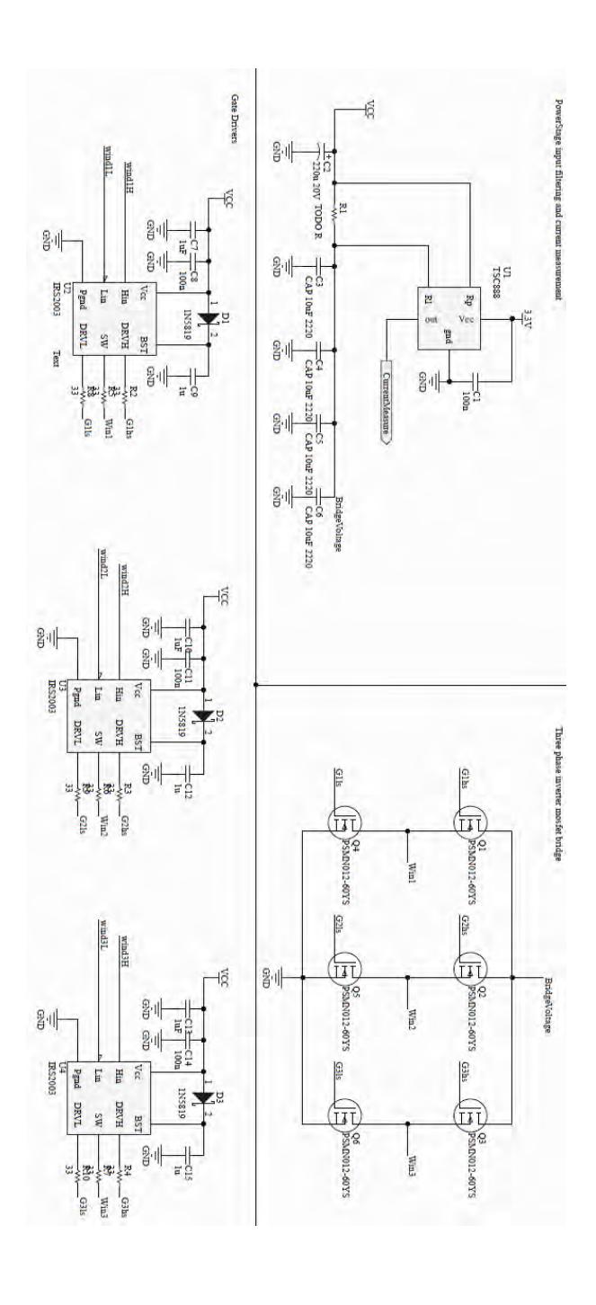
The signals coming from the motors are send back to the FPGA on the main controller board via pin headers. Via the same pin headers, control signals coming from the FPGA are fed down to the motor drivers. Discrete MOSFETs with gate drivers are used to maximize flexibility and minimize costs. The set up is a standard brushless H-bridge with gate drivers that use bootstrap capacitors to control the high side MOSFETs.
Next to the H-bridge, there is also current measurement capability implemented on the circuit board. This can be used for protection of the motors, and/or the driver electronics. Each motor also has a single status LED. This can help in debugging issues in the field. A schematic overview of the motor power electronics and H-bridge is shown in App. A.
There will still be research done in other areas to see if improvements can be made. An example of this are to use a separate rotary encoder for speed input for the PID controller. Another example is the use of a separate small microcontroller per motor to control it, instead of a single FPGA for all four brushless motors. This could give improvements in cost, complexity, and features such as current sensing.
3.5 Kickers Board
Current Design. The kicker board is in charge of boosting the voltage delivered by the internal batteries. Under normal operation, the 12V from the battery is boosted to 350V. The design is rated for a maximum of 400V to ensure safety. This is accomplished using an isolated DC/DC converter. The current version of the kicker uses a battery separated from the rest of the robot.
The power generated by the kicker board will be used to drive a series of solenoids, which can kick or chip the ball. Thee current kicker design is based around a standard boost converter. The isolation is obtained by making use of a secondary battery for powering the kicker system and controlling the the kicker via optically isolated inputs. The 34063 IC is used for controlling the boost converter, this IC has build-in current and voltage limiting by giving a pulse.
Future Design. The design of the kicker will be modified in the future to facilitate the use of a single battery in the robot without compromising the electrical isolation barrier between the input and the output of the robot. This is done by modifying the topology to a flyback converter. The main difference with the previously described implementation is that the coil is replaced by a transformer.
Another planned improvement is that the current version of the kicker board is controlled by the main PCB. The improved version will have a microcontroller which monitors the state of the kicker, such as input and output voltages, as well as controlling the output power to the solenoid.
3.6 Ball Detection
Ball detection is yet not implemented. However, this will be used later this year. Possible solutions can be an infrared (IR) LED and receiver, a laser diode and photo-transistor or a sonar/IR distance sensor.
3.7 Batteries
The main battery supplies the robot with power. Currently, a three cell LiPo battery is used, part of its specifications can be found in Table 3. LiPo batteries have advantages in being lightweight and small, and are generally widely available for a competitive price. The LiPo Battery has build in protection against over-(dis)charging and over-voltage protection. There are currently no additional safety features installed apart from a circuit breaker to prevent catastrophic failure due to shorts in the robot.
Table 3: Specifications of the batteries used
| Specification | Value |
|---|---|
| Maximum charge rate [C] | 5 |
| Maximum discharge rate [C] | 75 |
| Nominal output voltage [V] | 11.1 |
| Maximum power [W] | 14.4 |
3.8 Low Level Control
Motor Speed Controller. The speed controller currently implemented in the FPGA is done with a relatively simple PI controller. The commutation is also done in the FPGA for all four motors. The PWM generation to control the speed is separated from the winding commutation and will only affect the low side MOSFETs. If the high side MOSFETs do switch often, it will increase losses and discharges of the bootstrap capacitor.
Robot Position Controller. The robot position controller has two modes. When the commands to the robot are velocities, the robot calculates the angular velocities from the given velocity vector by means of kinematic matrix operations. This then gets converted from SI units to units that the FPGA can use. Lastly, the velocities get put in a package and sent via SPI.
When a position is sent to the robot, the control loop of the microcontroller gets activated. It now uses the given position as setpoint, the MTi data as the error and the angular velocities as output. The MTi gives data at regular intervals to ensure correct information. This way the position can be found precisely. More information about the MTi can be found in Sect. 3.3.
4 Software
4.1 Software Structure
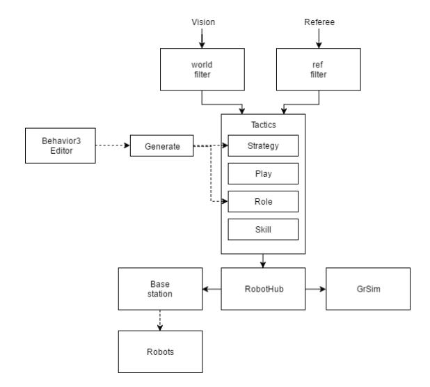
Overview. The software structure consists of several blocks, each representing a node which runs in a separate process, see Fig. 7. These nodes are based on and interconnected by the Robotic Operating System (ROS), which will be covered later in this section. All the solid arrows represent ROS communication lines over which the different nodes can post and receive data. At the top of the diagram, the incoming vision and referee data are filtered and sent to the tactics block, where this data is kept in memory until the next vision or referee update. The tactics block itself is separated into four layers; the structure will be detailed in Sect. 4.3. Once the tactics module has decided what every robot needs to do, it sends these commands to the RobotHub. This component is the interface between the tactics PC and the individual robots, managing the communication between them and performing all low-level transformations of data. Additionally, the RobotHub can be configured to send data to the GrSim simulation program [5] instead, which will then feed data to the vision system. To the tactics module, these two configurations look exactly the same, giving the ability to test the software in the simulation the same way it would run in the full system.
4.2 Behavior Trees
In several layers within the strategic architecture, behavior trees are used in order to determine how the robots should behave. Before explaining the strategy and tactics some information about these trees is given. Simply put, a behavior tree is a hierarchically structured set of actions, combined with conditions that specify which branch of the tree should be executed.
The use of behavior trees enables the team to speed up the process of creating and debugging strategies. Because behavior trees are easily constructed, one can quickly put together a new strategy to see how it performs. And because of the visual nature of behavior trees, it is expected that bugs are found more easily than in regular code.
This simplicity of behavior trees also gives the ability to involve people outside of the team in discussions about strategy. Even people who are inexperienced in computer programming, but well-versed in football strategy, can understand and contribute to behavior trees. At the moment the team is working on collaboration with human soccer teams. It is envisioned that if the process of creating and testing behavior trees is made simple and fun, many people will enjoy collaborating with the team to contribute to the soccer strategies.
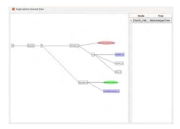
The formal version of behavior trees that we use is largely based on the work done by [6]. The described formal and general definition of behavior trees provides us with a robust platform for structuring our AI. Furthermore, a customized internal fork of the Behavior3 Editor is used for editing the behavior trees. Combined with custom tooling and interfaces in ROS and the rest of our tactics module we have already used behavior trees for various tasks, including debugging our robots and designing our qualification performance.
4.3 Strategy & Tactics
Strategic Architecture. The key challenge of the RoboCup Small Size League is intelligent coordination of a multi-robot system while dealing with rapidly changing circumstances and an unpredictable opponent. In order to ensure that all the robots always act according to the collective goal of scoring more goals than the opponent, a multi-level strategic planner has been developed. Just like many other SSL-teams an approach based on different levels of abstraction is used as described in [7].
On the lowest level a number of skills are defined. Skills are functions that transform specific, short-term goals for a single robot to low-level robot instructions. One level higher roles are used. A role is assigned to a single robot and determines which skill to execute with what parameters. Roles are generated from behavior trees. The next level is the plays layer. A play directs an arbitrary number of roles. When initializing the roles, it can decide on what parameters the role should use. And while the roles are running, the play keeps the overview and decides when to terminate the roles. On the highest level is the strategy. Only one strategy is running during any game. The strategy is generated from a behavior tree, just like a role, and determines which plays to execute based on the state of the game. The strategy also takes into account referee commands, and chooses the appropriate plays when new commands are issued.
The design of the software structure is based on requirements considered important, like flexibility and simplicity. The system developed is especially flexible, because a play can control any number of robots, rather than a fixed number. On top of that, behavior trees increase flexibility as discussed before in 4.2.
Skills. The most low-level nodes in the behavior trees are skills and conditions. Skills are functions that transform specific, short-term goals for a single robot, such as 'get the ball' or 'kick the ball', to velocity commands. This abstraction level allows for very concise and clear behavior trees in the higher levels of the strategic architecture, because most of the logic and computation is done within the skill.
Skills are functions that take certain input arguments, based on the task they are designed to perform, and output a velocity command for a single robot. Besides this simple functionality, however, skills also have access to the complete current state of the game, hence their output can be (partly) based on events currently happening in the field. Because skills are updated as soon as new information about the world state becomes available, it allows for quick responses to changing and unpredictable circumstances.
An example of one of the skills is the GoToPos skill, an advanced position controller, which takes as input argument a target position and orientation, and computes a velocity that moves the robot towards its goal. In addition, the GoToPos skills can take into account the position of all other robots in the field, and adapt the computed velocity such that it does not collide with them.
Another example of a skill is the ReceiveBall skill, which takes as input argument a position where a robot should wait to receive the ball. Then it computes the exact position where the robot can receive the ball, based on the current position and velocity of the ball, but also on whether another robot in the game is currently exerting influence on the ball and is expected to change its velocity.
Skills can internally call other skills and conditions, which allows for more complex behavior. Although this opens countless possibilities for skills, it is important to note that skills remain focused actions executed to achieve a specific, short-term goal. A situation in which skills can be combined is in the GetBall skill, which internally calls GoToPos in order to steer a robot towards the ball.
Conditions. Conditions can be used in behavior trees to determine which play, skill, or set of skills should be executed based on the state of the game. Conditions can be used in the strategy behavior as well as in the role behavior trees. A condition is a function that returns either true or false, based on which a certain branch of a tree can be chosen. Examples of conditions that are used are IHaveBall, BallOnOurSide and IsRefereeState.
Roles. A role is a behavior tree that is built up of skills and conditions and directs one robot. Unlike skills, the functionality of a role is quite simple. A role is basically a sequence of skills, combined with instructions on when to execute them. Combined with the behavior tree format this makes it very easy to construct and adapt roles. This means that once there is a sufficiently large base of skills it is very easy to quickly develop and test completely different strategies. It is also useful when working together with people who are very experienced in football strategy but not so much in computer programming.
Plays. A play directs an arbitrary number of roles that work together to reach a collective goal. When a play is initialized, it starts the relevant roles and chooses parameters for these roles based on the current state of the game. Every time the play is subsequently called, it checks whether the conditions for executing this play are still present, and whether the parameters given to the roles are still optimal. If they are not, it either quits executing or adapts the role parameters.
Strategies. The strategy is the highest level of abstraction within the strategic architecture. Only one strategy can be active at a time. A strategy chooses which plays should be executed. It does this partly based on the state of the game. The strategy also keeps track of referee commands, and only chooses plays that comply with the rules applicable to the current state of the game. A functionality that will be looked into in the future is a strategy which keeps track of all executed plays in a game and takes this information into account when choosing new plays in the rest of game.
4.4 Graphical User Interfaces
General. Most of the graphical tools are implemented in the graphical framework of ROS, called 'RQT'. This has the benefit that the Graphical User Interface (GUI) programs have full access to the messages being passed around in the software system.
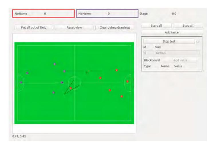
World View. The first GUI is the World View, as seen in Fig. 8. This view displays the positions of the robots and the ball, along with the basic referee messages. In addition to this, the world view can also display points and lines. These can be drawn by any node running in ROS by sending a line or point message over a ROS topic. This is primarily used by skills to visualize their internal calculations. This GUI can also be used to quickly test skills and roles by executing them from the panel on the right. The parameter set of the skill or role to be tested can be filled with the desired values before running it on the desired robot.
5 Conclusion
This paper described all the hard- and software of the RoboTeam Twente. Everything is described with detail to hopefully help new teams with building their own robots. There is still a lot of work to do this year, some possible improvements have been suggested. The big amount of students involved and resources available gives the possibility of endless improvements, especially the following months.
A Schematic Overview Motor Controller Board
References
- Adhami-Mirhosseini, A., Bakhshande Babersad, O., Jamaati, H., Asadi, S., & Ganjali, A. (2012). MRL Extended Team Description 2012. In Proceedings of the 15th International RoboCup Symposium, Mexico city, Mexico.
- Ganjali Poudeh, A., Sobhani, S., HosseiniKia, A., Karimpour, A., Mosayeb, S., Mahmudi, H., Esmaeelpourfard, S., Kassaeian Naeini, M., & Adhami, A. (2016). MRL Extended Team Description 2016. In Proceedings of the 20th International RoboCup Symposium, Leipzig, Germany.
- Ryll, A., Ommer, N., Geiger, M., Jauer, M., & Theis, J. (2015) TIGERs Mannheim Extended Team Description for Robocup 2015. In Proceedings of the 19th International RoboCup Symposium, Hefei, China.
- Yasui, K. et. al (2013). RoboDragons 2013 Extended Team Description Paper. In Proceedings of the 16th International RoboCup Symposium, Eindhoven, Netherlands.
- Monajjemi, V., Koochakzadeh, A., & Ghidary, S. (2012). grsimrobocup small size robot soccer simulator. RoboCup 2011: Robot Soccer World Cup XV, 450-460.
- Marzinotto, A., Colledanchise, M., Smith, C., & Ogren, P. (2014, May). Towards a unified behavior trees framework for robot control. In Robotics and Automation (ICRA), 2014 IEEE International Conference on (pp. 5420-5427). IEEE.
- Browning, B., Bruce, J., Bowling, M., & Veloso, M. (2005). STP: Skills, tactics, and plays for multi-robot control in adversarial environments. Proceedings of the Institution of Mechanical Engineers, Part I: Journal of Systems and Control Engineering, 219 (1), 33-52.