2017 Team Description Paper: UBC Thunderbots
Chuan Yu Bai, Winnie Gong, Ben Hers, Ben Hsieh, Ryan De Iaco, Yi Zhou Ju, Brandon Jury, Bruce Long, Kevin Lynx Lu, James Petrie, Khashina Tonks-Turcotte, Cheng Xie, Dingqing Yang, Ryan Zaari, Kevin Zhang, Zhikai Zhang
The University of British Columbia Vancouver, BC, Canada
Abstract This paper details the design improvements the UBC Thunderbots has made in preparation for RoboCup 2017 in Nagoya, Japan. The primary focus was to create a better mechanical system through improving the drivetrain, dribbler, and chipper and kicker. The secondary focus involved building upon the electrical system and the existing artificial intelligence.
1 Introduction
UBC Thunderbots is an interdisciplinary team of undergraduate students at the University of British Columbia. Established in 2006, it pursued its first competitive initiative within the Small Size League at RoboCup 2009. The team has consecutively competed in RoboCup from 2010 to 2016 and is currently seeking qualification for RoboCup 2017. Over the years, it has made significant developments of its team of autonomous soccer playing robots. This paper will outline the progress in implementation of the current model of robots, focusing on the mechanical, electrical and software components with particular emphasis on the mechanical and electrical systems.
2 Mechanical Design
(No introductory text)
2.1 Drivetrain
(No introductory text)
Motor Mount Symmetrical Re-design
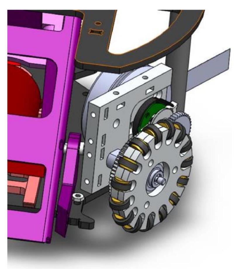
Two critical features are added to the new motor mount (Figure 1): anti-stripping and perfect symmetrical design. Anti-stripping is achieved by a M2.5 nut cut out; this cut out will be collinear with the mounting hole on the bottom of the motor mount. Different from previous motor mount, the mounting holes are no longer threaded, and the M2.5 nut takes the full axial load. We will only need to replace the nut or the screw if breakage happens instead of fixing the thread on the motor mount.
Perfect symmetrical design is achieved by adding redundant features. In previous motor mount design, motor mounts only contain features that are unique to their location. This new design combines all necessary features in a unified design. The same motor mount could be mounted it horizontally, vertically, on the left-hand side, or on the right-hand side.
Gearing system re-design
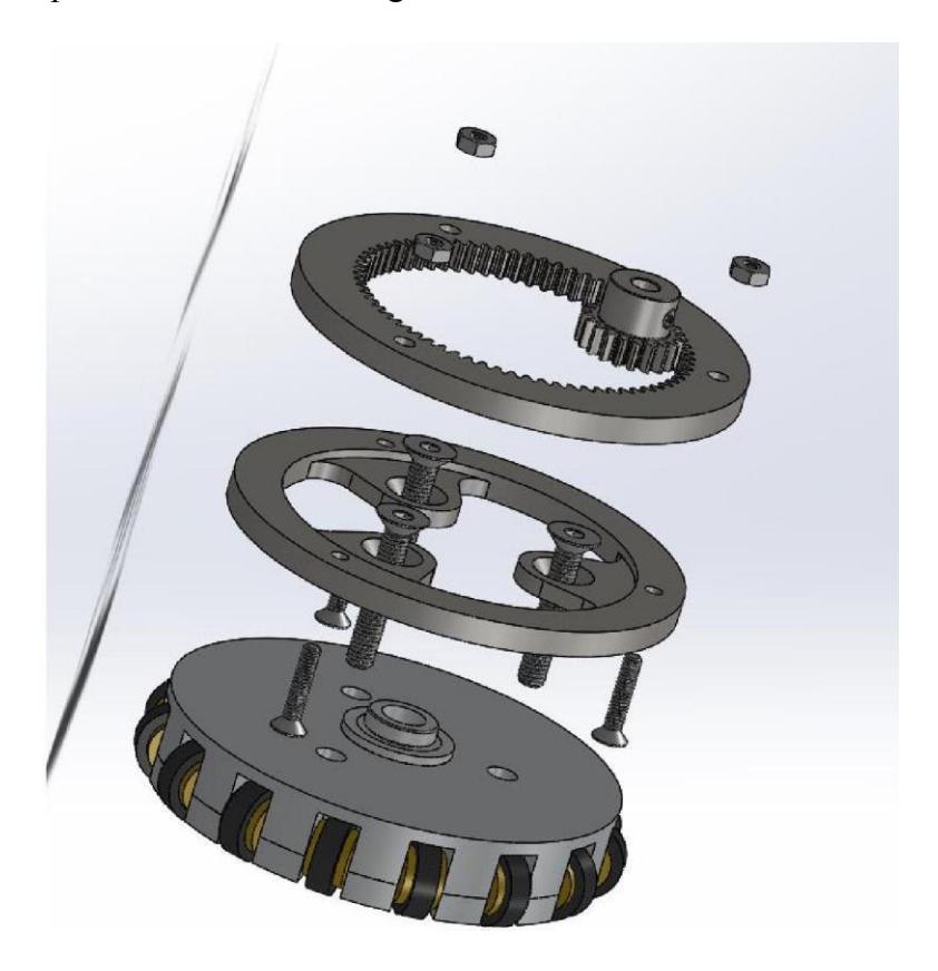
Current spur gear design is prone to external fluff, dirt, and other alien objects. The internal gearing system inherently protects the mechanical component from external disturbance. Figure 2 shows the assembly of the internal gearing system. To accommodate for the necessary changes to internal drivetrain system, a new wheel and a new coupling mechanism are made to match the standard internal gear. In the near future, a new encoder plate and a motor mount will be designed to compensate for the internal gear.
Wheel slipping prevention mechanism
Due to limited manufacturing accuracy, there is a consistent unevenness in wheel contact. To combat this issue, development of an anti-slipping mechanism that will work without high accuracy machining was initiated. Two ideas are proposed at this stage. The first one is to make the motor mount's height adjustable. Hence, the user can easily calibrate each wheel individually until all of them are touching the ground evenly. The second one is to develop a spring damping system that will automatically compensate for the wheel that is not touching the ground. Both idea will be manufactured and tested for feasibility in the next generation of robots.
2.2 Dribbler
(No introductory text)
Frame
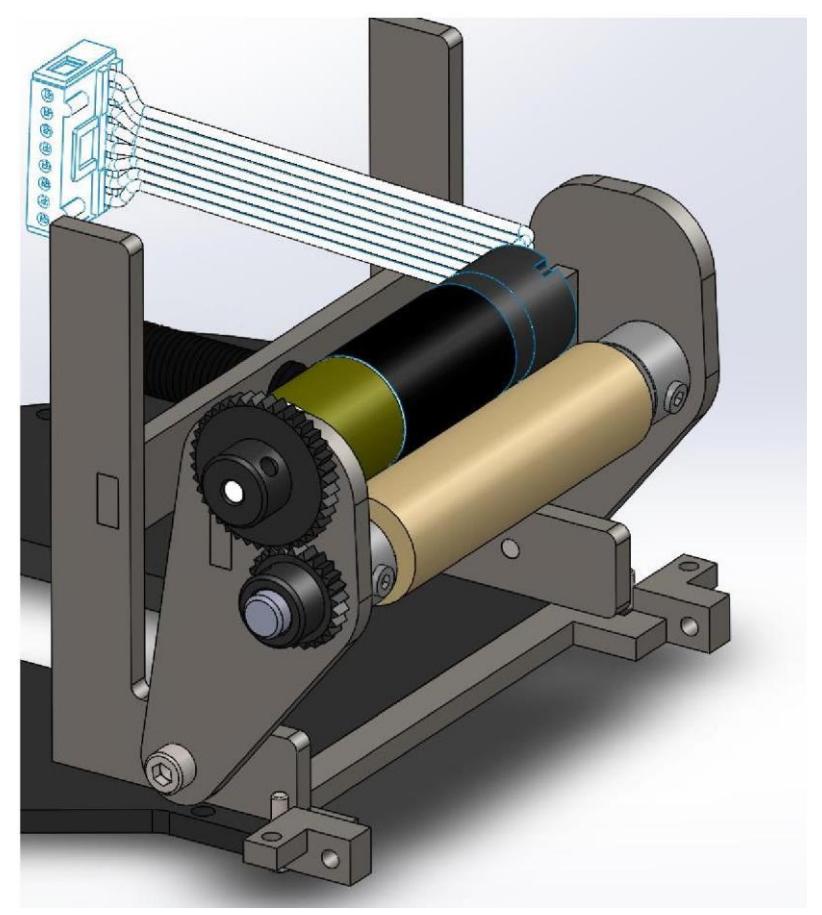
Previously, the dribbler, motor, and gearing slid along two diagonal mounts to create a linear motion when receiving the ball. However, this setup allowed the dribbler system to tilt horizontally when impacted, thus affecting dribbling negatively.
This year, a new frame that will rotate back when impacted by the ball was designed (Figure 3). Since the height of each side will no longer depend on individual springs compressing when the dribbler makes contact with the ball, this design will greatly reduce lateral play and make dribbling more repeatable.
Break Beam
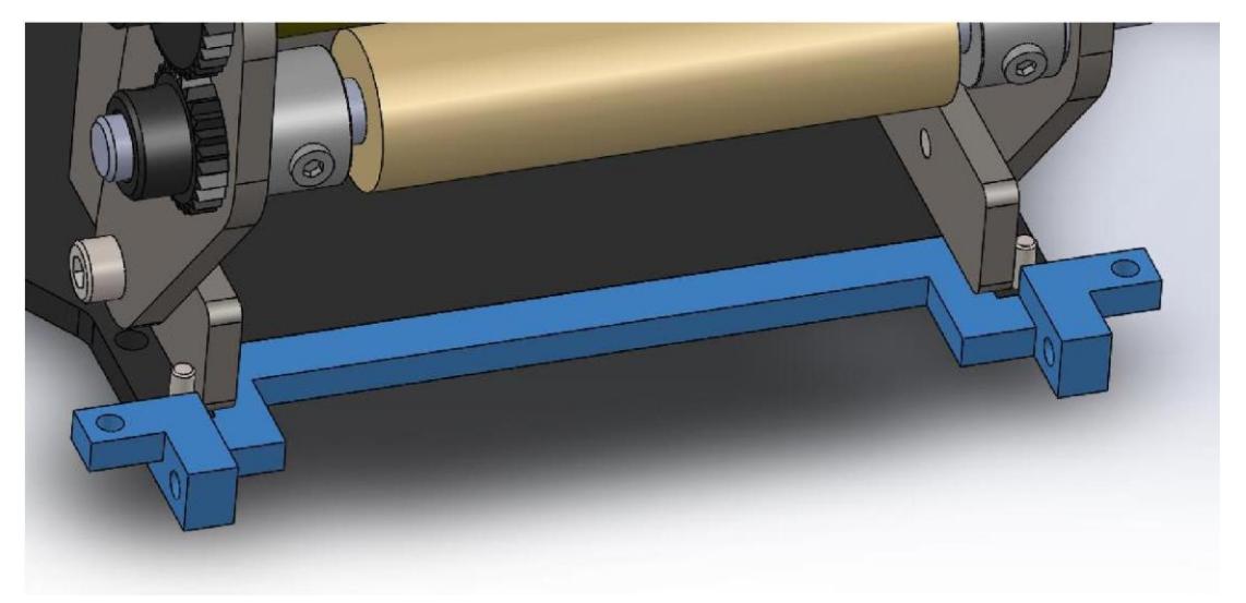
Instead of a break beam mount composed of two separate parts across from each other, the sides are combined into one solid piece to greatly reduce the possibility of misalignment (Figure 4). This also prevents the creation of false logical "highs" when impacted.
2.3 Chipper/Kicker
(No introductory text)
Shooting Mechanism Overhaul
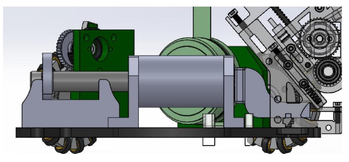
With the previous generation robots, a major issues lies in the inconsistency of the chipper as well as the space usage of the design. Work is being done on creating a stacked solenoid topology where the chipper mechanism lies underneath the kicker assembly which greatly reduces wasted space (Figure 5). A groove is created on the thickened baseplate which allows for the flat solenoid to be embedded at baseplate level. The kicker plunger is reshaped to allow for the elevated kicker solenoid while maintaining the same ball contact point as before. A new elevated back stopper is implemented for the repositioned kicker plunger to prevent the kicker head from impacting the solenoid.
Solenoid Rework
The robot is undergoing current mechanical and subsequent electrical redesign for a future version. The wire housing for the kicker and chipper solenoids have been adjusted in dimension and placement. A result of this is a need for prototyping of the kicker and chipper solenoids so that they perform similarly to the current competition ready model. Given the new design, test rigs were constructed using the new kicker and chipper designs. The kicker solenoid wire housing was 3D printed and wound using a small motor winding system. The kicker solenoid design was tested using predetermined winding parameters, but it under performed compared to the kicker solenoid currently being used in the robot. Next steps include increasing the number of windings on the kicker solenoid so that it performs equally well compared to the current kicker solenoid. Similar prototyping steps are being carried out in parallel for the new chipper solenoid design including test rig construction, 3D printing, wire winding and adjustments to the number of wire windings to produce an equivalently performing chipper solenoid.
3 Electrical Design
(No introductory text)
3.1 Electronics
Our overall electronic design has mostly stayed the same from last year. There have been some modifications to our chicker board (the board carrying the electronics necessary for chipping and kicking) to make it more mechanically robust, as well as the integration of an LPS (Lateral Positioning Sensor) to more accurately detect ball location.
On our current iteration of the chicker board, there is a 3 mF capacitor bank which stores the energy required to power our solenoid chipper and kicker. This bank is charged to 240 VDC. Due to the large amount of energy stored in this circuit, we have included a safety discharge circuit in case a robot is shut off unexpectedly while the capacitors are still charged. In our previous iteration of this circuit, the resistors used in the discharge circuit were mounted upright, and were prone to snapping off the board. In our new iteration of the chicker board, we have moved components around and re-routed it in such a way that there is room for the discharge resistors to lay flat, which should improve the mechanical robustness of said resistors.
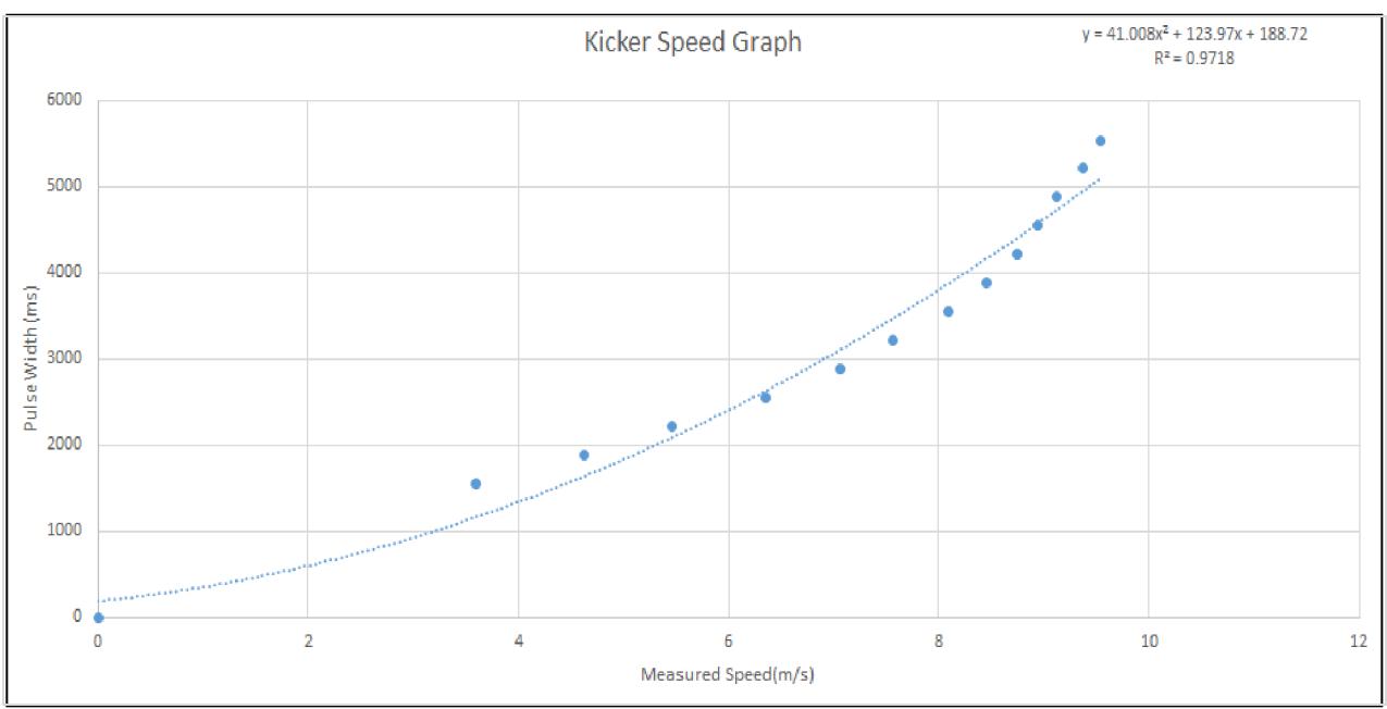
With our change from a 4 capacitor bank to a 3 capacitor bank, the chicker board also needed to be recalibrated so that the software could accurately control the speed at which the ball was kicked. This was done by adjusting the code based on newly collected data of the three-capacitor system. The original equation used to calculate the capacitor pulse width needed to kick the ball at a certain speed was stored in the robot firmware, so we sent various kick commands at different speeds to the robot via our testing software. The actual speeds of the ball were obtained and recorded by projecting a sample ball through a speed gate, while the speeds manually set on the testing software were converted to the capacitors pulse width. Using this data, we created a plot that represented Measured Speed (x) vs Pulse Width (y) on Microsoft Excel and recalibrated the software by using a line of best fit. This new equation was then inputted back into the firmware and used for a second round of testing, which was then used to refine our equation in pursuit of an accurate representation of the robot's kicking speed. This process of testing and calibrating the equation continued, until the resulting equation was insignificantly different than the previous equation, at which point we considered it was accurate enough for use (see Figure 6).
One of the improvements we sought to achieve this year was to better predict how the ball would react to a given chip or kick. To do this, we have integrated an LPS to measure the ball position within our dribbler, which should help us to kick/chip the ball when it is in an optimal location. The LPS works by emitting light through four lasers and having four phototransistors convert the reflected light into current. We hope to derive a relationship between the voltage values received through the phototransistors and different locations of a ball relative to the sensor; we are currently in the middle of doing extensive testing. Ideally, in the end we will also be able to determine a relationship between the ball kicking and chipping trajectory as a function of the location of the ball along the chipper.
3.2 Control
One of the key issues we've had in controlling our robots is related to wheel slip. Wheel slip is problematic because our low-level control relies heavily on wheel encoder data to calculate the robot's position. There are three key projects we have worked on this year to address wheel slip. The first is to mathematically determine if wheel slip is occurring based on the encoder data. The second was to rewrite our radio protocol such that camera data could be sent directly to the robot to augment our low-level control. The final project involved sensor fusion to better predict the location of the robot in between sent camera frames.
Based on the robot's wheel encoder data, we are able to detect when the robot's wheels have started slipping. Our process for doing so is based on the ideas described in Omnidirectional Control [1]. First, we calculate the velocity coupling matrix D, which maps the robot's Euclidean velocity vector $\mathbf{v} = (v_x \ v_y \ R\omega)^T$ to robot's individual velocity vector $\mathbf{m} = (v_1 \ v_2 \ v_3 \ v_4)^T$ . Then, we calculate the pseudo-inverse of D that gives the inverse mapping from the individual velocity to the robot's Euclidean velocity. We denote this pseudo-inverse matrix as $D^+$ . If the wheel speed is consistent (i.e. no slip), mapping the encoder data (measured individual wheel velocity) to the Euclidean space and mapping the result back to the 4 dimensional space of individual wheel speeds should give the same result as measured data. Mathematically speaking, $\mathbf{m}' = DD^+\mathbf{m}'$ , where $\mathbf{m}'$ denote the encoder data for each wheel. Rearranging the equation, we have reached the conclusion that the wheel slip occur if $(I-DD^+)\mathbf{m}'$ gives a non-zero result. To verify this conclusion, we have recorded some real-time encoder data at the moment that wheel slip occurs, and have used Matlab to analyze the measured data. We find that all the data gives a non-zero result, which validates our conclusion. However, this method is not able to indicate which wheel slips.
Our radio protocol was also updated this year. Our old protocol was designed before we implemented movement primitives (the basic skills of the robot, such as moving to a point) and thus we were not using our radio packets optimally. In our new protocol, we have broken packets into two distinct types, a camera packet and a message packet. Camera packets are sent to all robots, and contain a vector of all the robot positions and orientations (with their associated timestamp), as well as the estimated ball position. Message packets contain robot specific requests, such as which primitive to execute. By reorganizing our radio protocol, we are now able to stream camera data directly to the robots, which has improved our ability to control our robots such that they accurately execute their required movement primitives.
Finally, we attempted to implement a Kalman filter to better estimate the position of our robot in between camera frames. The goal was to use the on-board accelerometer and gyroscope data in addition to the wheel encoder data to get an overall better estimate of the robot's position than if the wheel encoder data was used alone. To remove noise from the accelerometer we used a low pass filter, and to reduce gyroscope drift we used a high pass filter. However, due to the poor quality of our accelerometer data on the short time intervals between streamed camera frames, our Kalman filter was not effective.
Upon analysis of our wheel slip problem, we recognized that wheel slip was primarily causing over-compensation in the angular direction of our robot's trajectory planning. Since the gyroscope data and the wheel encoder data were of high quality, we decided to develop a complementary filter based on the gyroscope and wheel encoder data to get a better estimate for the true orientation of the robot. Further work is required on this solution, and in the future we may look to use a Kalman filter with just the angle of the robot as the state, as opposed to including the robot's x-y position as well. Ideally this filter would provide the low-level controller with a better estimate of the current state of the robot then it currently has with just the wheel encoder data.
4 Software
(No introductory text)
4.1 Action Termination Condition
This year we improved upon the new coroutine framework that we implemented last year (discussed in our 2016 TDP). A major improvement we had is with the "action" layer that provides a basic set of movements that interface with the robots. Actions are stateless functions that are called upon by higher level functions and set waypoints in the robot navigator.
Sequential execution of tactics was not possible prior to this year due to the actions not having end conditions that determine when to return and continue on to proceeding functions. Since the robot and navigator do not inherently have conditions to check for completion, the actions that call them have to manually check and remove them. The movements that are supported by the robots are as follows:
- 1.Stop
- 2.Move
- 3.Dribble
- 4.Shoot
- 5.Catch
- 6.Pivot
- 7.Spin
For Move, Dribble and Pivot, the movement ends when the robot when the player moves within a specified radius around the destination and reaches a certain velocity. However, the conditions for Stop and Spin are a lot more difficult to define. In this case, there is no end condition implemented since stopping (in general) can be performed immediately, and the time to wait is context dependent. The calling function will instead perform an evaluation to terminate the movement.
These changes will allow future maneuvers to be more complex and call upon more advanced decision trees in the AI.
4.2 Improving robustness of ball-tracking algorithm
Currently the ball-tracking algorithm is flawed as it is unable to handle some noise that frequently occurs in games. A major problem is the ball position data contained in camera packets potentially contains clusters of points that could be perceived by the current algorithm as a standalone ball. This is problematic because when this type of noise does appear, the selection of which cluster to pursue in game is arbitrary. The current algorithm essentially takes the weighted average of measurements, which is clearly ineffective when false positives show up in the camera feed.
One proposed solution is to perform clustering on past data received in the past half-second to second. By deliberately tracking clusters of data and attaching a ball model to the ball tracking algorithm, the camera will be able to make informed decisions on the true location of the ball.
The most likely cluster will be chosen using a physics model for the ball and some hysteresis. The main goal of this improvement is to make the ball-tracking algorithm more resilient to clusters of incorrect ball data. A useful subgoal is to include the ability to track multiple balls on the playing field at once.
Initial testing has been done in MATLAB. Past game data where this kind of noise is significant has been used to compare this ball-tracking improvement to the original flawed implementation. A MATLAB script is used to simulate a game, and filtered data is generated by applying this clustering technique. Almost all results have seen an overall improvement in ball-tracking, but the issue is still not entirely resolved as there are still many scenarios where the ball is incorrectly tracked. It is likely that the ball-likelihood algorithm, the state-predictor, needs to be improved.
4.3 Camera Latency Correction Using Wheel Encoders
Prior to this project, the movement primitive update and camera latency was seen to reduce the stability of movement. The purpose of this project was to improve the accuracy of the state estimation algorithm and improve movement precision. This was accomplished by streaming camera data to the robots and accounting for the measurement latency using wheel encoders.
A large component of this project was handling camera data without adding much more of a delay and creating a new type of radio packet to transmit the data at 30Hz to all of the robots. A separate thread was used to timestamp incoming data and add it to a queue. The main thread then sends the newest data over the radio every tick with an estimate for the additional delay incurred on the data.
C code was written on the robots to handle the new type of radio packet. In addition, wheel encoder measurements are recorded every firmware tick (5ms) and stored in a circular buffer. When new position data is received the robot sets that as its starting position and sums the stored wheel encoder data to account for the latency. Currently we are using an estimate of the delay between the host computer and the receiving robots to account for transmission and processing latency. This estimate has given us acceptable results in our testing so far, and may be refined in the future to attain high precision control.
4.4 Investigating Deep Reinforcement Learning for Smart Path Planning
Reinforcement learning has been studied for a long time. Q-learning has been well studied and applied to settings like Backgammon. Recently, reinforcement learning has been the focus of much research. Due to advances in deep learning, traditional reinforcement learning approaches have been extended to settings such as Atari and even robotics [3][4].
We have begun exploring the use of deep reinforcement learning to the domain of Robocup SSL. In reinforcement learning, we are interested in developing learning agents that are able to learn policies that maximize reward. To this end we created OpenAI gym environments to simulate simple tasks like navigating around obstacles. At each timestep an agent receives the state of the environment, picks an action and receives the next state as well as a reward signal.
Based on this setup the agent will be able to gradually improve its policy to optimize its expected total reward. In our previous preliminary experiments we have used a simple DQN model to learn optimal ball interception policies [2]. The reward in this setting is the proximity of the robot to the ball and the state space includes the position and velocities of the ball and robot. The action that the agent produces corresponds to discrete accelerations in 4 directions to be taken at that timestep.
Currently we are working on improving these methods by implementing newer advances in deep reinforcement learning including continuous action spaces and model based learning in order to create smoother movement patterns and more intelligent behaviour as well as investigating how well these approaches could transfer to the domain of physical robots.
4.5 Improving set-plays and chip-and-chase
Currently, the robots do not have any logic when it comes to what to do on a friendly free kick. Previously, the robots would shoot straight at the net, which would always be blocked by an enemy and we would lose any chance of maintaining possession. To solve this, new evaluation functions and decision algorithms were added to choose between several different options. Based on the positions of enemy robots, the player will either shoot or chip at the net, chip-and-chase with another player, or intentionally deflect the ball off the enemy to try get another kick.
To evaluate the chip-and-chase, a target open area on the field is chosen. This is done by treating each enemy robot and the corners of the fields as vertices, and triangulating these points. These largest of these triangles that does not contain enemy robots is then chosen, and its centre becomes the target for the chip. The robot designated to receive the chip calls this same evaluation function so it also knows where the chip target is. It can then get into a position to receive the chip. These additions would allow the robots to react in more varied ways against defenses. Since free kicks make up a large portion of play, improving the behaviour in these conditions would greatly improve the effectiveness of our robots' offensive tactics.
5 Conclusion
We believe that the design chances detailed above will lead to significant improvements in performance. We look forward to putting the changes into action at RoboCup 2017.
6 Acknowledgements
We would like to thank our sponsors, as well as the University of British Columbia, specifically, the Faculty of Applied Science and departments of Mechanical Engineering, Engineering Physics, and Electrical and Computer Engineering. Without their continued support, developing our robots and competing at RoboCup would not be possible.
References
- R. Rojas. (2005, May, 18) Omnidirectional Control [online] Available: http://robocup.mi.fu-berlin.de/buch/omnidrive.pdf.
- R. De Iaco, S. Johnson, F. Kalla, L.K. Lu, M. MacDougall, K. Muthukuda, J. Petrie, M. Ragoonath, W.Y. Su, V. Tang, T. Tsu, B. Wang, G. Whyte, C. Xi, K. Yu, E. Zhang, and K. Zhang, "2016 Team Description Paper: UBC Thunderbots," 2016.
- Deep Reinforcement Learning for Tensegrity Robot Locomotion. Xinyang Geng*, Marvin Zhang*, Jonathan Bruce*, Ken Caluwaerts, Massimo Vespignani, Vytas SunSpiral, Pieter Abbeel, Sergey Levine. ICRA 2017.
- Mnih, V., Kavukcuoglu, K., Silver, D., Graves, A., Antonoglou, I., Wierstra, D., and Riedmiller, M. Playing atari with deep reinforcement learning. In arXiv preprint arXiv:1312.5602, 2013.