ULtron 2017 Team Description Paper
Philippe Babin, Alexia Blanchard-Lapierre, Simon Bouchard, Maxime Gagnon-Legault, Alexandre Gingras-Courchenes, Léonard L. Gagnon, Philippe Lebel, Philippe Turgeon
Université Laval, Québec QC, Canada
Abstract This paper presents the work done since 2013 by the team ULtron in order to participate in the international competition. Since it is the team's first attempt to participate in the competition, this article will present a summary of all the sections of the robots and compare upgrades from this year to previous iterations of the robot.
1 Introduction
ULtron is a team of undergraduate and graduate students at Université Laval in Quebec city, Canada. The team is active since 2013. This year, for the first time, the team has produced a complete team of robots and is ready to compete against other teams in the Small Size League (SSL) competition. The team is used to present the project to the public in local events, schools, local fairs and exhibitions to promote robotic and artificial intelligence.
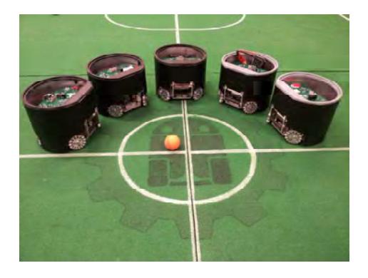
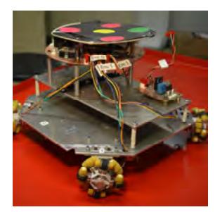
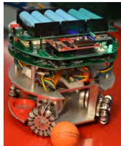
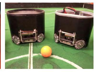
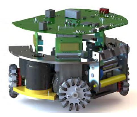
Since the beginning of the project, the team has produced three iterations of robots, one each year, as illustrated in Fig. 2. The first one, called Alpha, was a proof of concept to ensure that the project could be completed, from the mechanical and electrical designs to the control by the artificial intelligence team. Next, the Beta robot was the first robot built by the team that follows the requirements in size of the competition rules. Finally, the Gamma revision, as seen in Fig. 3 and Fig. 1, is the first competition ready robot. A team of six Gamma robots was built and another one is planned to be assembled in order to have a replacement robot at the competition.
In this paper, a review of the Gamma robot's design is stated and the progress since the previous Beta version is highlighted. More specifically, the design is exposed through three perspectives, in the following order: mechanical design, electrical and embedded design and artificial intelligence.
2 Mechanical design
This section describes the mechanical design of the Gamma robot.
2.1 Wheels
The robots use four omni-directional wheels positioned at 90 degrees of each others so the combination of rotation enables moving in any direction. Brushless motors are used with a 3:1 gear ratio. We chose the 30 W Maxon Flat Motor with 2048Imp included encoder.
As for the power transmission solution, the design was inspired from the numerous papers published by veteran teams. As the team saw, a lot of teams opted for the internal gear setup installed directly on omni wheels. Since the team's design already had smaller omni wheels, the concepts seen on most robot had to be adapted.
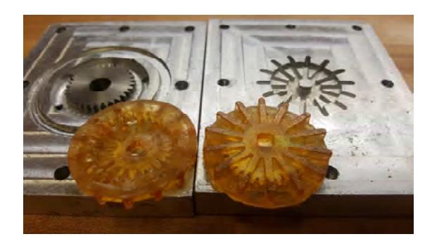
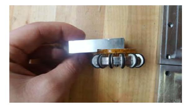
To reduce production costs and meet manufacturing constraints, the team chose to mold the gears with polyurethane. Fig. 4 represents the apparatus used to produce the gears and Fig. 5 represents how the gear is assembled with the omni wheels.
The gears are able to sustain the stress caused by normal robot usage and cost about 0.1 US $ of material each. The estimate cost of similar internal gears seen on the market revolves around 100 US $ each and require machining to be included in the design which is a big incentive to choose the molding process over buying the gears. Laser cut plastic gears were also considered for the solution, but since the omni wheels were too small to directly secure the gear on them, the team had to find a way to fix the gear to the shaft supporting the wheels. This last consideration required the gears to have a "backplate" and rendered the laser cutting process impossible.
2.2 Kicker
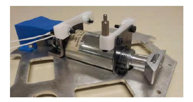
The kicker design is simple and based on a tubular push type solenoid. It is actually a machined solenoid, model S-20-125-22H from Magnetic Sensor Systems. The modifications allow the installation of a plunger designed by the team as in Fig. 5.
Fig. 6. Previous versions like the Beta used the original plunger, but the force of repetitive kicks were damaging the pushing arm.
The pushing arm is 11 mm in diameter and is made of two materials. The ferromagnetic part is made of C12L14 steel and the non-ferromagnetic part is made of aeronautic grade aluminum (7075 t6). It has been designed to sustain a 10 m/s kick of a ball while the robot is moving 4 m/s toward the ball.
2.3 Dribbler
Injection molded rubber cylinders are used to induce a spin to the play ball. Many tests were done to achieve the maximal backspin possible. With the designed device, the ball stays near the robot. A 15 W DC motor is used with a belt drive to spin the cylinder. Two infrared detectors are placed above the metal frame to detect the presence of the play ball.
3 Electrical design
This section describes the electrical design and control systems of the robot.
3.1 Main Board
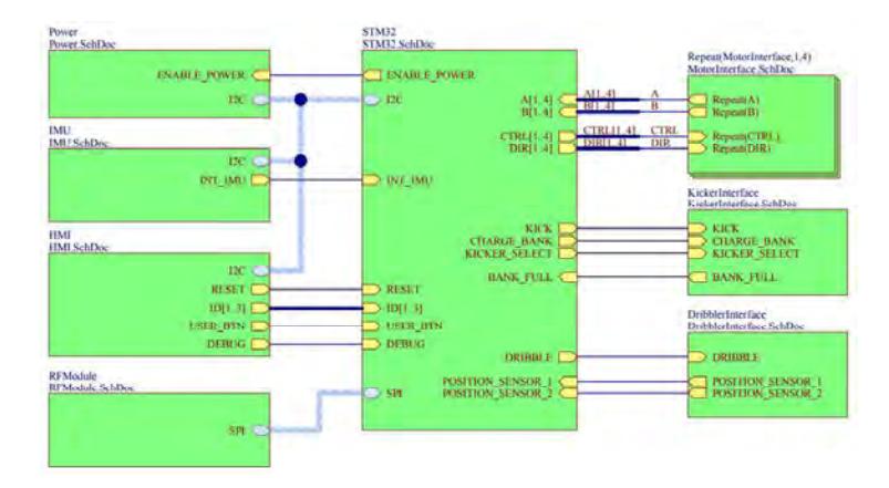
The main board host a STM32F4 microcontroller (MCU) which control every sections of the robot. The architecture of this board is illustrated in Fig. 7 and the 3D view of the developed printed circuit board (PCB) is shown in Fig. 8. Pulse width modulation (PWM) signals are sent to the motor drives and the encoder signals from the brushless motors are directly fed to the MCU internal counters. The main board is a four layers PCB with two internal layers used for the power and ground plane. The battery is monitored through a I2C bus with an INA219 current sensor to collect data like power consumption and to avoid battery under-voltage. The dribbler activation MOSFET is also present on the main board. Only connectors for the motor drives, the kicker manager sections and the dribbler's motor are placed on the PCB. All the low voltage logic section of the main board is electrically isolated from the power sections to avoid electromagnetic problems due to the high currents of the motors and kicker. To do so, all the signals between those two sections are isolated with optocoupler integrated circuit. This new version of our robot, the Gamma, include an isolated DC/DC converter to provide the power to the logic part from a single battery pack (see sec. 3.2 for more details) without the need of two separated batteries as it was on the Beta version. The STM32F4 runs a real-time operating system (FreeRTOS). The microcontroller execute three tasks: one that handle the communication, one that handle the speed motor control and a slower one that handles the kicker and the dribbler. The speed of each wheel is controlled by a PI regulator in order to follow the speed commands sent by the base station. The embedded source code is available here: https://github.com/RobocupUlavalEmbedded/RobotMCU.

3.2 Battery pack
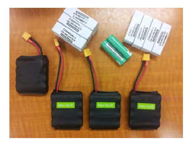
The custom battery pack is made of four individual 18650 Li-ion cells (see Fig. 9). It has a capacity of 2000 mAh with a nominal voltage of 14.8 V to allow each robot to be used for at least 90 minutes. Unlike previous version of the robot, a protection circuit board is placed inside the package to prevent battery over-discharge or short circuit. The pack is held together with spot-welded nickel strips.
3.3 Motor drive
Each motor is controlled by an integrated circuit motor driver (LB11920 - ON Semiconductor) mounted on a different PCB as shown in Fig. 8. The four PCBs are connected to the main board using edge connectors to minimize cabling and to enable a quick replacement of the main board. The PCB is welded directly to the motor connectors (which were removed). A PWM signal is sent from the MCU to command each wheel's speed.
3.4 Kicker manager
The solenoid actuator used to kick the ball is driven by a single circuit board (see Fig. 8). This PCB is placed in the center of the robot. The circuit receive a control signal from the main board, charge two 400 V 1000 $\mu$ F capacitors to a high voltage and then discharge through the solenoid on a kick signal. The charge circuit uses a Linear Technology LT3750 IC to fully charge the capacitor in five seconds with a 200 kHz switching signal applied to a transformer to increase voltage. The kick trigger is applied to a large insulated-gate bipolar transistor (IGBT) to discharge the capacitor in the solenoid during a precise period to adjust kicking force. A protection discharge circuit was added to dissipate this energy when the robot is shut down and a neon lamp is added to each capacitors to show if they are charged.
3.5 Wireless communication
Wireless communication is done by a NRF24L01P IC to receive and send data to the base station. Different messages are sent to each robot, like speed vector or kick command. The commands are sent using a bi-directional communication protocol. The protocol sends a COBS encoded payload from the base station to the robot. The commands are sent through a USB connection from the base station to a communication tower. The latter is made of a STM32F4 and a NRF24L01P circuit to wirelessly distribute the commands to the corresponding robots. Then, the robot receives, executes and acknowledges it to the base station.
4 Artificial Intelligence
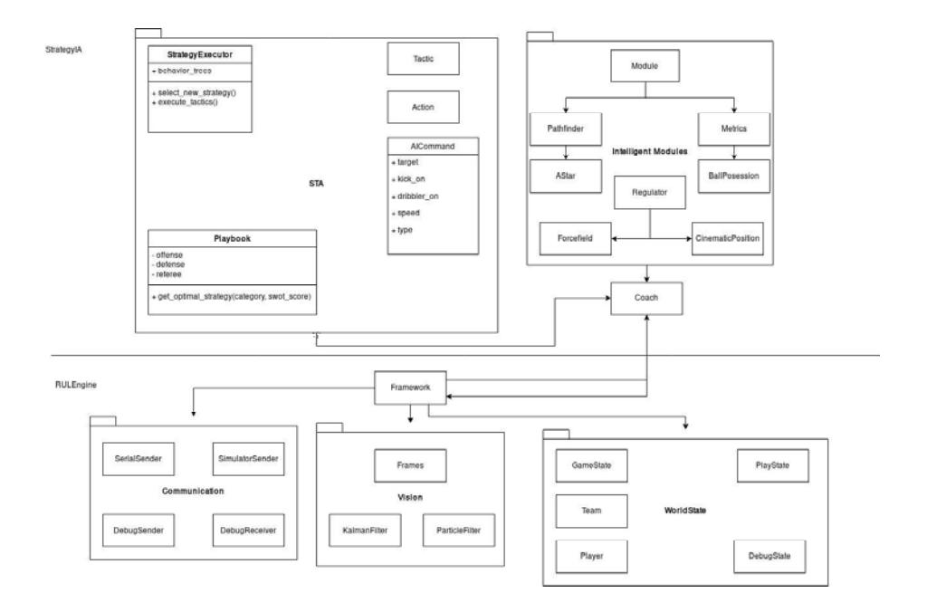
There are two main modules for controlling the robots. The RULEngine (https://github.com/RobocupUlaval/RULEngine) module wraps the other module. The main purpose of this module is to manage the communication with the robot, vision, and referee as well as updating the objects' state on the field. The StrategyIA (https://github.com/RobocupUlaval/StrategyIA) module takes strategic decisions and creates commands to send to the robots.
4.1 RULEngine framework
The RULEngine receives data from the vision server and update the game state (field geometry, positions, teams). A Kalman filter [2] is used to help with vanishing and noise on the different measurements and a multi-particle filter [3] is use to handle the camera overlap which gives different measurements of the same object. The following enumeration presents the main loop of the program that controls the robots on the field:
- Analysis and filtering of the vision's data to determine the current game state;
- (a) Kalman filter (to estimate each robot's position and speed);
- (b) Particule filter (to estimate the ball's position).
- The game state is updated according to the new informations;
- The StategyIA is called to determine the robot actions (see next subsection);
- The commands from the AI are sent to the robots on the field.
4.2 StrategyIA
This section describes the strategy module and its components.
Strategy Selector
Multiple strategies exist to handle the various game situations that can occur in play. Those are regrouped into a playbook. The playbook contains various sections: offense, defense, referee (i.e: new play, penalty shoot, etc.). The strategy selector query the game state for various metrics to form a 4D vector. This vector is based on a SWOT analysis. Each strategy is assigned a SWOT score and the closest in the correct section is selected. The SWOT score of a strategy is computed by hand based on results. Finally the module evaluate if the strategy need to be updated, based on the time since the last strategy update, the game state and the difference of SWOT score between the actual strategy and the new strategy. A referee command immediately overrides this module and the appropriate strategy is selected to obey the command.
STA system
The STA system is composed of 3 components: The Strategy, the Tactic and the Action.
– Strategy:
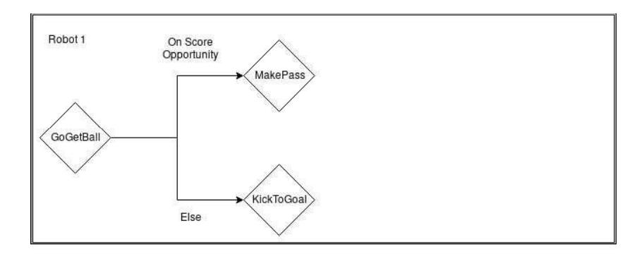
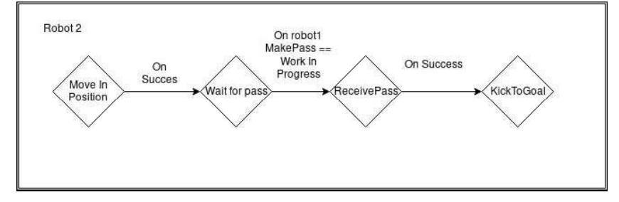
The strategy module is responsible to assign roles, also known as Tactic, to each robot. To make those decisions, six behavior trees are created and updated each AI iterations. The nodes represent Tactics and the edges are decisions that are required to be true for the strategies to go on. A simple decision can be for example: "is player X finished positioning itself to receive a pass".
- Tactic:
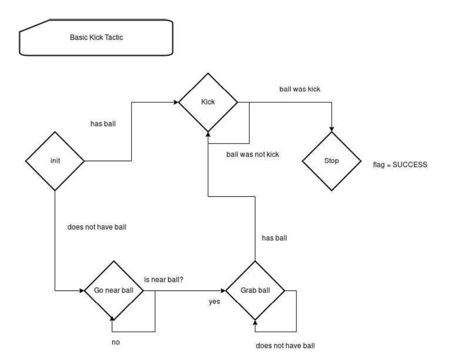
A tactic is a state machine. Each state produces a command to be sent and executed by a robot. State transition allows a sequence of actions to efficiently take place and react to quick changes in the game state. Kicking the ball toward a target is a good example of a tactic. Tactics can also be composed, as a state can also be a tactic. Furthermore, to assist the decision of a player's behavior tree, a tactic also updates its status during its execution. This status informs the Strategy layer of the completion and the success of the tactic.
- Action:
An action is a way to create a command based on the game state and other parameters fed by a tactic. These actions allow to isolate simple logic to compute destination positions or generate multiple commands.
Intelligent modules
The intelligent modules are a set of algorithms that influence the game state and the play state, which are the AI's decisions. They help to take better decisions before and after a tactic is chosen. Some modules of the packages are the A* pathfinder[4], the potential field algorithm for collision avoidance [5] and the control loop of the robots positions and orientations based on two parallel PID controllers.
These are updated at regular interval and can run in separate threads if they need to do long computation. Some modules can be written only to help design strategy by producing visual representation of the game state (i.e. a heat map of a robot influence zone).
5 Conclusion
A description of the technology used to produce the ULtron robot team has been presented. The team's first competition robots are ready to be used to implement more complex strategies. Currently, the team is working on making the mechanical and electrical system more robust as well as improving the embedded system's control loop and developing an artificial intelligence that can play a full game on its own.
References
- Browning B., Bruce J., Bowling M., & Veloso M. (2004), STP: Skills, tactics and plays for multi-robot control in adversarial environments. IEEE Journal of Control and Systems Engineering, 219, 33-52.
- Kalman, R. E. (1960). A new approach to linear filtering and prediction problems. Journal of basic Engineering, 82(1), 35-45.
- Beppu, T., Aoki, S., & Horiuchi, T. (2016, May). A Shared Multi-particle Filter for Ball Position Estimation in RoboCup Small Size League Soccer Games. In Autonomous Robot Systems and Competitions (ICARSC), 2016 International Conference on (pp. 311-316). IEEE.
- Hart, P. E., Nilsson, N. J., & Raphael, B. (1968). A formal basis for the heuristic determination of minimum cost paths. IEEE transactions on Systems Science and Cybernetics, 4(2), 100-107.
- Barraquand, J., Langlois, B., & Latombe, J. C. (1992). Numerical potential field techniques for robot path planning. IEEE Transactions on Systems, Man, and Cybernetics, 22(2), 224-241.